Page 1559 of 4087
 and (d)).
w If any one of the connecting rod cap bolts is broken or
deformed, re")
B. Install connecting rod cap boltsHINT:
wThe connecting rod cap bolts are tightened in 2
progressive steps (steps (b) and (d)).
w If any one of the connecting rod cap bolts is broken or
deformed, replace it.
(a) Apply a light coat of engine oil on the threads and under the heads of the connecting rod cap bolts.
(b) Install and alternately tighten the 2 connecting rod cap bolts
in several passes.
Torque: 25 N Vm (250 kgf Vcm, 18 ft Vlbf)
If any one of the connecting rod cap bolts does not meet the
torque specification, replace the connecting rod cap bolts.
(c) Mark the front of the connecting cap bolt with paint.
(d) Retighten the cap nuts 90 � as shown.
(e) Check that the painted mark is now at a 90 � angle to the front.
(f) Check that the crankshaft turns smoothly.
8. CHECK CONNECTING ROD OIL CLEARANCE
Using a dial indicator, measure the thrust clearance while
moving the connecting rod back and forth.
Standard thrust clearance:
0.160 ± 0.290 mm (0.0063 ± 0.0138 in.)
Maximum thrust clearance: 0.35 mm (0.0138 in.)
If the thrust clearance is greater than maximum, replace the
connecting rod assembly(s). If necessary, replace the crank-
shaft.
Connecting rod thickness:22.880 ± 22.920 mm (0.9008 ± 0.9024 in.)
±
1UZ±FE ENGINE ENGINE MECHANICALEG±183
WhereEverybodyKnowsYourName
Page 1609 of 4087

Minimum diameter: 7.40 m")
6. INSPECT MAIN BEARING CAP STUD BOLTSUsing a vernier caliper, measure the tension portion diameter
of the stud bolt.
Standard diameter: 7.500±7.600 mm
(0.2953±0.2992 in.)
Minimum diameter: 7.40 mm (0.2913 in.)
If the diameter is less than minimum, replace the stud bolt.
7. IF NECESSARY, REPLACE MAIN BEARING CAP STUD BOLTS
(a) Using the two main bearing cap nuts, remove the studbolt.
(b) Apply a light coat of engine oil on the threads and under
the flange of the stud bolt.
(c) Using the two main bearing cap nuts, install and torque
the stud bolt.
Torque: 10 N Vm (100 kgf Vcm, 7 ft Vlbf)
HINT: Stud bolts come in lengths of 90.0 mm (3.543 in.) and
101.5 mm (3.996 in.). Install the 101.5 mm (3.996 in.) bolts
in inside positions. Install the 90.0 mm (3.543 in.) bolts in out-
side positions.
DISASSEMBLY OF PISTON AND
CONNECTING ROD ASSEMBLIES
1. CHECK FIT BETWEEN PISTON AND PISTON PIN
Try to move the piston back and forth on the piston pin.
If any movement is felt, replace the piston and pin as a set.
EM±144
±
ENGINE MECHANICAL Cylinder Block
WhereEverybodyKnowsYourName
Page 1624 of 4087
 Match the numbered c onnecting rod cap with the
connecting rod.
(b) Align the pin groove of the connecting rod cap w")
6. INSTALL CONNECTING ROD CAPS
A. Place connecting rod cap on connecting rod(a) Match the numbered c onnecting rod cap with the
connecting rod.
(b) Align the pin groove of the connecting rod cap with the pins of the connecting rod, and install the connecting rod
cap.
(c) Check that the outside mark on the connecting rod cap is facing in correct direction.
B. Install connecting rod cap bolts HINT:
wThe connecting rod cap bolts are tightened in two
progressive steps (steps (b) and (d)).
w If any one of the connecting rod bolts is broken or
deformed, replace it.
(a) Apply a light of engine oil on the threads and under the
heads of the connecting rod cap bolts.
(b) Usin g SS T, in sta ll an d alte rn a te ly tig h te n th e two connecting rod cap bolts in several passes.
SST 09011±38121
Torque: 25 N Vm (250 kgf Vcm, 18 ft Vlbf)
If any one of the connecting rod cap bolts does not meet the
torque specification, replace the connecting rod cap bolt.
(c) Mark the front of the connecting rod cap bolt with paint.
±
ENGINE MECHANICAL Cylinder BlockEM±159
WhereEverybodyKnowsYourName
Page 1714 of 4087
 Check that the timing marks of the camshaft timingpulleys and timing belt rear plates aligned.
If not, turn the crankshaft one revolution (360 5).
27. REMOVE TIMING BELT TENSIONER HINT:
w(Re±u")
(b) Check that the timing marks of the camshaft timingpulleys and timing belt rear plates aligned.
If not, turn the crankshaft one revolution (360 5).
27. REMOVE TIMING BELT TENSIONER HINT:
w(Re±using timing belt)
If the installation marks have disappeared, before re-
moving the timing belt, place new installation marks on
the timing belt to match the timing marks of the camshaft
timing pulleys, and place a new installation mark on the
timing belt to match the end of the hydraulic pump.
w (When replacing timing belt tensioner only)
To avoid meshing of the timing pulley and timing belt, se-
cure one of them with string. And place matchmarks on
the timing belt and RH camshaft timing pulley.
Alternately loosen the two bolts, and remove them, the ten-
sioner and dust boot.
28. DISCONNECT TIMING BELT FROM CAMSHAFT TIMING PULLEYS
(a) Using SST, loosen the tension between the LH and RHcamshaft timing pulleys by slightly turning the LH
camshaft timing pulley clockwise.
SST 09278±54012
±
ENGINE MECHANICAL Timing BeltEM±41
WhereEverybodyKnowsYourName
Page 1723 of 4087
 Using SST, align the timing marks of the LH camshaftpulley and timing belt rear plate.
SST 09278±54012
(e) Check that the timing belt has tension between the crankshaft timing pulley and LH c")
(d) Using SST, align the timing marks of the LH camshaftpulley and timing belt rear plate.
SST 09278±54012
(e) Check that the timing belt has tension between the crankshaft timing pulley and LH camshaft timing pulley.
14. INSTALL TIMING BELT TO RH CAMSHAFT TIMING PULLEY
(a) Remove any oil or water on the RH camshaft timing andwater pump pulley, and keep them clean.
(b) Using SST, slightly turn the RH camshaft timing pulley clockwise. Align the installation mark on the timing belt
with the timing mark of the camshaft timing pulley, and
hang the timing belt on the RH camshaft timing pulley.
SST 09278±54012
(c) Using SST, align the timing marks of the RH camshaft pulley and timing belt rear plate.
SST 09278±54012
(d) Check that the timing belt has tension between the RH
camshaft timing pulley and LH camshaft pulley.
15. SET TIMING BELT TENSIONER (a) Using a press, slowly press in the push rod using981±9,807 N (100±1,000 kgf, 220±2,205 lbf) of
pressure.
(b) Align the holes of the push rod and housing, pass a 1.27
mm hexagon wrench through the holes to keep the
setting position of the push rod.
(c) Release the press.
(d) Install the dust boot to the tensioner.
EM±50
±
ENGINE MECHANICAL Timing Belt
WhereEverybodyKnowsYourName
Page 1744 of 4087
 Using a 45 � carbide cutter, resurface the valve seats.
Remove only enough metal to clean the seats.
(b) Check the valve seating position.
Apply a thin coat of")
8. INSPECT AND CLEAN VALVE SEATS(a) Using a 45 � carbide cutter, resurface the valve seats.
Remove only enough metal to clean the seats.
(b) Check the valve seating position.
Apply a thin coat of prussian blue (or white lead) to the valve
face. Lightly press the valve against the seat. Do not rotate
the valve.
(c) Check the valve face and seat for the following: w If blue appears 360 � around the face, the valve is
concentric. If not, replace the valve.
w If blue appears 360 � around the valve seat, the
guide and face are concentric. If not, resurface the
seat.
w Check that the seat contact is in the middle of the
valve face with the following width:
Intake 1.0±1.4 mm (0.039±0.055 in.)
Exhaust 1.2±1.6 mm (0.047±0.063 in.)
If not, correct the valve seats as follows:
(1) If the seating is too high on the valve face, use 15 5
and 45 5 cutters to correct the seat.
(2) If the seating is too low on the valve face, use 75 5
and 45 5 cutters to correct the seat.
±
ENGINE MECHANICAL Cylinder HeadEM±47
WhereEverybodyKnowsYourName
Page 1751 of 4087
 Using a plastic±faced hammer, lightly tap the valve stem
tip to assure proper fit.
4. INSTALL VALVE LIFTERS AND SHIMS (a) Install the valve lifter and shim.
(b) Check that the valve lifter r")
(d) Using a plastic±faced hammer, lightly tap the valve stem
tip to assure proper fit.
4. INSTALL VALVE LIFTERS AND SHIMS (a) Install the valve lifter and shim.
(b) Check that the valve lifter rotates smoothly by hand.
INSTALLATION OF CYLINDER HEAD
(See Components on pages EM±34 and 35)1. INSTALL CYLINDER HEAD
A. Place cylinder head on cylinder block (a) Place a new cylinder head gasket in position on thecylinder block.
NOTICE: Be sure to install it correctly.
(b) Place the cylinder head in position on the cylinder head
gasket and connect the heater water hose to the union.
B. Install cylinder head bolts
HINT:
wThe cylinder head bolts are tightened in two progressive
steps (steps (c) and (f)).
w If any of bolts break or deform, replace them.
(a) Apply a light coat of engine oil on the threads and under
the heads of the cylinder head bolts.
(b) Install the 14 plate washers to each cylinder head bolt.
(c) First, using a 10 mm bi±hexagon wrench, uniformly tighten the cylinder head bolts in several passes in the
sequence shown.
Torque: 34 N Vm (350 kgf Vcm, 25 ft Vlbf)
If any one of the bolts does not meet the torque specification,
replace the bolt.
EM±54
±
ENGINE MECHANICAL Cylinder Head
WhereEverybodyKnowsYourName
Page 1752 of 4087
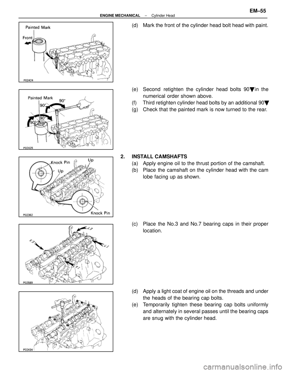
(d) Mark the front of the cylinder head bolt head with paint.
(e) Second retighten the cylinder head bolts 90� in the
numerical order shown above.
(f) Third retighten cylinder head bolts by an additional 90 �.
(g) Check that the painted mark is now turned to the rear.
2. INSTALL CAMSHAFTS (a) Apply engine oil to the thrust portion of the camshaft.
(b) Place the camshaft on the cylinder head with the camlobe facing up as shown.
(c) Place the No.3 and No.7 bearing caps in their proper location.
(d) Apply a light coat of engine oil on the threads and under
the heads of the bearing cap bolts.
(e) Temporarily tighten these bearing cap bolts uniformly
and alternately in several passes until the bearing caps
are snug with the cylinder head.
±
ENGINE MECHANICAL Cylinder HeadEM±55
WhereEverybodyKnowsYourName