Page 1974 of 4087
4. REMOVE CUP HOLDERUsing a screwdriver, pry out the rear side of the cup holder.
Remove the cup holder.
5. REMOVE UPPER REAR CONSOLE PANEL Using a screwdriver, pry out the console panel.
6. REMOVE UPPER CONSOLE PANEL (a) Remove the six mounting screws.
(b) Using a screwdriver, pry out the console panel.
7. REMOVE RADIO (a) Remove the five mounting bolts.
(b) Disconnect the wiring connectors and antenna cable,
and remove the radio.
8. DISCONNECT SUB±OXYGEN SENSOR CONNECTORS FI±119
EFI SYSTEM
± Electronic Control System (Sub±Oxygen Sensors)
WhereEverybodyKnowsYourName
Page 1975 of 4087
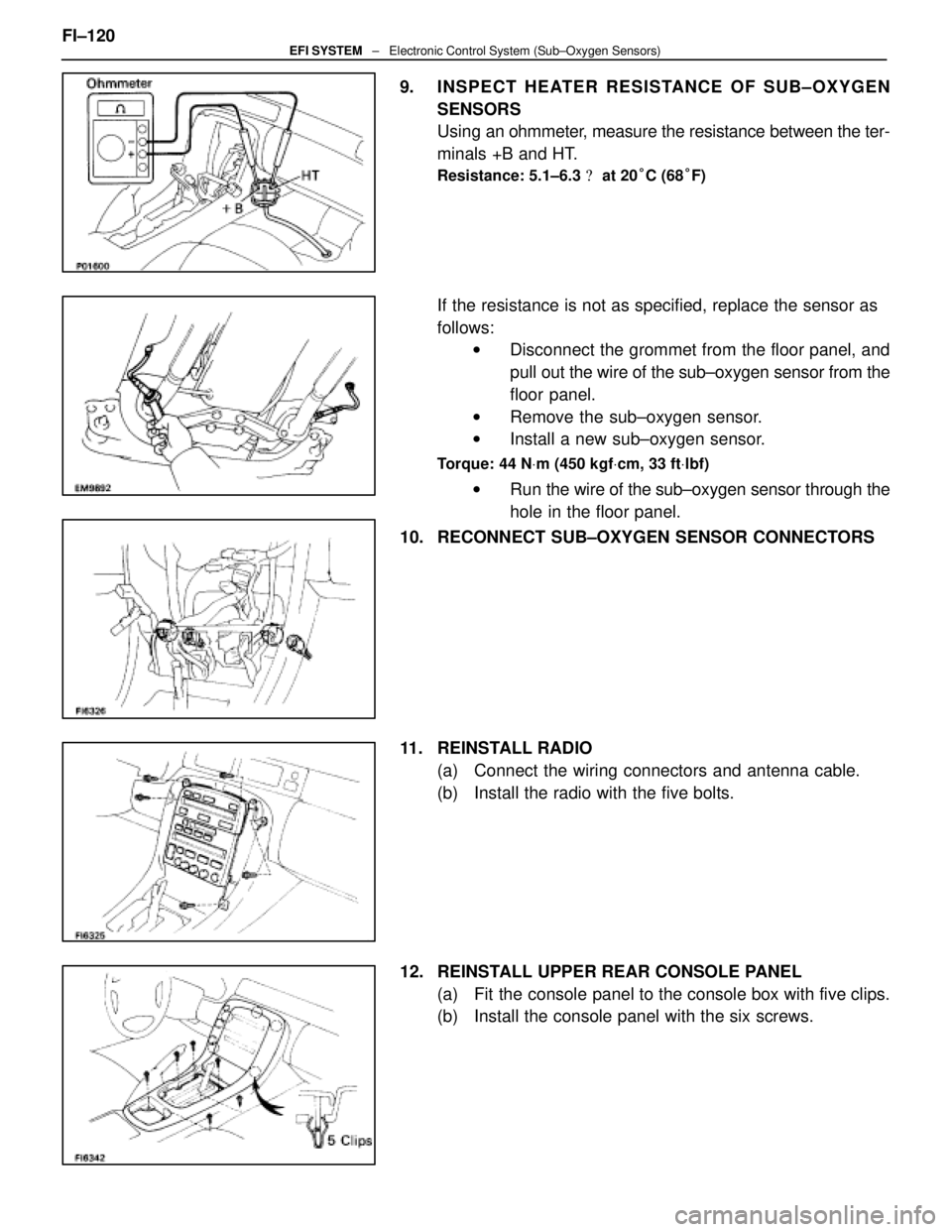
9. INSPECT HEATER RESISTANCE OF SUB±OXYGEN
SENSORS
Using an ohmmeter, measure the resistance between the ter-
minals +B and HT.
Resistance: 5.1±6.3 � at 20 °C (68 °F)
If the resistance is not as specified, replace the sensor as
follows:
w Disconnect the grommet from the floor panel, and
pull out the wire of the sub±oxygen sensor from the
floor panel.
w Remove the sub±oxygen sensor.
w Install a new sub±oxygen sensor.
Torque: 44 N Vm (450 kgf Vcm, 33 ft Vlbf)
w Run the wire of the sub±oxygen sensor through the
hole in the floor panel.
10. RECONNECT SUB±OXYGEN SENSOR CONNECTORS
11. REINSTALL RADIO (a) Connect the wiring connectors and antenna cable.
(b) Install the radio with the five bolts.
12. REINSTALL UPPER REAR CONSOLE PANEL (a) Fit the console panel to the console box with five clips.
(b) Install the console panel with the six screws.
FI±120
EFI SYSTEM
± Electronic Control System (Sub±Oxygen Sensors)
WhereEverybodyKnowsYourName
Page 1976 of 4087
13. REINSTALL UPPER CONSOLE PANELFit the console panel to the console box with the four clips.
14. REINSTALL CUP HOLDER Fit the cup holder to the console box.
15. REINSTALL TRANSMISSION SHIFT LEVER KNOB (a) Slide the lever cover on the lever shaft.
(b) Install the shift lever knob with the two screws.
(c) Attach the l ever cover to the lower side of the lever knob.
16. RECONNECT CABLE TO NEGATIVE TERMINAL OF BATTERY FI±121
EFI SYSTEM
± Electronic Control System (Sub±Oxygen Sensors)
WhereEverybodyKnowsYourName
Page 1984 of 4087

TerminalNo.SymbolConnectionTerminalNo.SymbolConnection
E10± 21NCOT/M Input Speed SensorE10 ± 51±
22±52HTL2LH Sub±Oxygen Sensor Heater
23SP2No.2 Speed Senso")
TERMINALS OF ENGINE & ECT ECU (Cont'd)
TerminalNo.SymbolConnectionTerminalNo.SymbolConnection
E10± 21NCOT/M Input Speed SensorE10 ± 51±
22±52HTL2LH Sub±Oxygen Sensor Heater
23SP2No.2 Speed Sensor for ECT53HTR2RH Sub±Oxygen Sensor Heater
24±54±
25G2LH (No.2) Cam Position Sensor55±
26G1RH (No.1) Cam Position Sensor56IGT2No.2 Igniter for RH Bank
27NEEngine Speed Sensor57IGT1No.1 Igniter for LH Bank
28VF2Check Connector58IGF1No.1 Igniter for LH Bank
29VF1Check Connector59IGF2No.2 Igniter for RH Bank
30±60±
31±61±
32ISC4ISC Valve62±
33ISC3ISC Valve63IDL2Sub±Throttle Position Sensor
34ISC2ISC Valve64IDL1Throttle Position Sensor
35ISC1ISC Valve65E2Sensor Ground
36*� EGR4EGR Valve66KSAir Flow Meter
37*� EGR3EGR Valve67OXR2
38*� EGR2EGR Valve68OXL2LH Sub±Oxygen Sensor
39*� EGR1EGR Valve69E1ECU Ground39*� EGRVSV for EGR69E1ECU Ground
40±70±
41VCThrottle Position Sensor
Air Flow Meter71HTL1LH Main Oxygen Sensor
42VTA2Fuel Pump ECU72HTR1RH Main Oxygen Sensor
43VTA1A/C Magnet Clutch Relay73FPUVSV for Fuel Pressure Control
Value
44THWWater Temp. Sensor74*� PA GVSV for EVAP
45THAIntake Air Temp. Sensor75±
46THGEGR Gas Temp. Sensor76NSWNeutral Start Switch
47OXR1RH Main Oxygen Sensor77STAStarter Relay
48OXL1LH Main Oxygen Sensor78STJCold Start Injector
49KNK2RH (No.2) Knock Sensor79E02Power Ground
50KNK1LH (No.1) Knock Sensor80E01Power Ground
Engine & ECT ECU Terminals
*��USA spec. only
* �� A/T only
FI±127EFI SYSTEM ± Electronic Control System (Engine & ECT ECU)
WhereEverybodyKnowsYourName
Page 1995 of 4087

Water temp.
sensorResistanceat ±20°C (±4 °F)
at 0 °C (32 °F)
at 20 °C (68 °F)
at 40 °C (104 °F)
at 60 °C (140 °F)
at 80 °C (176 °F)10 ± 20 k �
4 ± 7 k �
2 ± 7 k")
SERVICE DATA (Cont'd)
Water temp.
sensorResistanceat ±20°C (±4 °F)
at 0 °C (32 °F)
at 20 °C (68 °F)
at 40 °C (104 °F)
at 60 °C (140 °F)
at 80 °C (176 °F)10 ± 20 k �
4 ± 7 k �
2 ± 7 k �
0.9 ± 1.3 k �
0.4 ± 0.7 k �
0.2 ± 0.4 k �
EGR gas
temp.
sensorResistanceat 50°C (112 °F)
at 100 °C (212 °F)
at 150 °C (302 °F)69 ± 89 k �
12 ± 15 k �
2 ± 4 k �
Main oxygen
sensorHeater coil resistance5.1 ± 6.3 �
Sub±oxygen
sensorHeater coil resistance5.1 ± 6.3 �
ECUHINT:
�Perform all voltage and resistance measurements with the ECU connected.
� Verify that the battery voltage in 11 V or above with the ignition switch is ON.
Voltage
TerminalsConditionSTD voltage (V)
BATT ± E1±10 ± 14
IGSW
+B ± E1
+B1
IG SW ON10 ± 14
VC ± E2±4.0 ± 6.0
IDL1E2
Throttle (or sub±throttle) valve fully closed1 or lessIDL1
IDL2 ± E2
IG SW ONThrottle (or sub±throttle) valve fully open10 ± 14
VTA1E2
Throttle (or sub±throttle) valve fully closed0.1 or lessVTA1
VTA 2 ± E2
Throttle (or sub±throttle) valve fully open3.0 ± 6.0
KS ± E1IdlingPulse generation
THA ± E2
THW±E2Idling
Intake air temp. 20
°C (68 °F)1.0 ± 3.0
THW ± E2IdlingEngine coolant temp. 80 °C (176 °F)0.1 ± 1.0
STA ± E1Cranking6.0 or more
#10
#20
E01IG SW ON10 ± 14#20
#30
#40±
E01
E02IdlingPulse generation
IGT1
IGT2
± E1IdlingPulse generation
FI±138EFI SYSTEM
± Service Specifications
WhereEverybodyKnowsYourName
Page 1999 of 4087

TORQUE SPECIFICATIONS
Part tightenedNVmkgf Vcmft Vlbf
Fuel line Union bolt type
Flare nut type2930022
Fuel pipe X Delivery pipe39400 29
Fuel pump bracket X Fuel tank5.455 48 in.Vlbf
Fuel pump set plate X Fuel tank3.940 35 in. Vlbf
Fuel tank X Body25250 18
Fuel sender gauge X Fuel tank2.930 26 in. Vlbf
Fuel inlet pipe X Fuel tank2.930 26 in. Vlbf
Fuel tank main tube X Fuel tank29300 22
Fuel tank return tube X Fuel tank29300 22
Fuel tank evaporation vent tube X Fuel tank29300 22
Air flow meter X Air cleaner case10100 7
Cold start injector X Air intake chamber7.880 69 in. Vlbf
Cold start injector tube X Cold start injector15150 11
Air intake chamber X Intake manifold18185 13
EGR pipe X Air intake chamber18185 13
EGR pipe X RH cylinder head18185 13
Cold start injector tube X RH Delivery pipe15150 11
Throttle body X Air intake chamber18185 13
Fuel return pipe X Fuel pressure regulator35360 26
Fuel pressure regulator X RH delivery pipe29300 22
Delivery pipe X Intake manifold18185 13
Fuel inlet hose X LH delivery pipe39400 29
for SST33340 24
ISC valve X Air intake chamber18185 13
Cold start injector time switch X Front water by±pass joint34350 25
Water temperature sensor X Front water by±pass joint20200 14
Water inlet housing X Water pump18185 13
EGR gas temperature sensor X EGR valve adaptor20200 14
EGR valve adaptor X Air intake chamber18185 13
EGR valve X EGR valve adaptor18185 13
Knock sensor X Cylinder block44450 33
Intake manifold X Cylinder head18185 13
Main oxygen sensor X Exhaust manifold44450 33
Sub±oxygen sensor X Exhaust manifold4445033
FI±142EFI SYSTEM ± Service Specifications
WhereEverybodyKnowsYourName
Page 2003 of 4087

The EFI system is composed of three basic sub±systems: Fuel, Air Induction and Elect\
ronic Control
Systems.
FUEL SYSTEM
An electric pump fuel pressure supplies sufficient fuel, under a constant pressure, to the EFI injectors. In
accordance with signals from the ECU (Electronic Control Unit), these \
injectors inject the quantity of fuel most
appropriate for the engine condition into the intake manifold.
AIR INDUCTION SYSTEM
The air induction system provides sufficient air for engine operation.
ELECTRONIC CONTROL SYSTEM
The 1UZ±FE engine (ECU±formerly EFI computer) with a microcomputer \
centrally controls the EFI, ESA,
ISC and Diagnosis system, etc. The ECU controls the following functions:
1. Electronic Fuel Injection (EFI)
The ECU receives signals from various sensors indicating changing engine op\
eration conditions such as:Intake air volume
Intake air temperature
Coolant temperature
Engine rpm
Acceleration/deceleration
Exhaust oxygen content etc.
The signals are utilized by the ECU to determine the injection duration nec\
essary for an optimum air±fuel
ratio.
2. Electronic Spark Advance (ESA) The ECU is programmed with data for optimum ignition timing under any and all opera\
ting conditions. Using
data provided by sensors which monitor various engine functions (rpm, coola\
nt temperature, etc.), the
Electronic Control Unit (ECU) triggers the spark at precisely right instant. (S\
ee IG section)
3. Idle Speed Control (ISC) The ECU is programmed with idle speed data for various engine conditions (\
coolant temperature, air condi-
tioner ON/OFF, etc.).
The air volume flowing through the throttle valve by±pass passage is adj\
usted according to the signal from
each sensor and the idle speed is kept at the set value.
4. Diagnosis Function When the ECU detects any malfunctions or abnormalities in the sensor network\
, it lights the ºCHECKº en-
gine warning light in the combination meter. At the same time, the trouble is identified and a diagnostic code
is recorded by the ECU. The diagnostic code can be read by the number of\
blinks of the ºCHECKº engine
warning light when terminals TE1 and E1 are connected. The diagnostic co\
des are refer to the later page.
(See TR section)
5. Self±Correction Function If any sensor malfunctions, an average value recorded in the back±up ci\
rcuit is substituted to make driving
possible.
If danger is predicted, the engine is stopped and the ºCHECKº engine\
warning light will light up.
6. Fail±Safe Function Even if an abnormality occurs in the ECU, the back±up circuit uses a specifie\
d fuel injection and ignition
timing to provide vehicle driveability, and also lightsup the ºCHECKº engine warning light.
FI±4
EFI SYSTEM
± Description
WhereEverybodyKnowsYourName
Page 2008 of 4087
ELECTRONIC CONTROL SYSTEM
The control system consists of sensors which detect various engine conditio\
ns, and a ECU which determines
the injection volume (timing) based on the signals from the sensors.
The various sensors detect the air intake volume, engine rpm, oxygen densit\
y in the exhaust gas, coolant tem-
perature, air intake temperature and atmospheric pressure etc. and convert the inf\
ormation into an electrical
signal which is sent to the ECU. Based on these signals, the ECU calculates th\
e optimum ignition timing for the
current conditions and operates the injectors.
The ECU not only controls the fuel injection timing, but also the self diag\
nostic function which records the oc-
currence of a malfunction, ignition timing control, idle rpm control, EGR contro\
l, EVAP control, ACIS and fuel
pump control, which switches between the high and low fuel pump speeds accor\
ding to varied load conditions. FI±8
±
EFI SYSTEM Operation
WhereEverybodyKnowsYourName


 based on the signals from the senso")