Page 1469 of 4087
(b) Remove the main heated oxygen sensor.
(c) Remove the 8 nuts, exhaust manifold and gasket.
EG11C±06
CYLINDER HEAD DISASSEMBLY
(See Components for Removal and Installation)
1. REMOVE VALVE LIFTERS AND SHIMSHINT: Arrange the valve lifters and shims in correct order.
2. REMOVE VALVES
(a) Using SST, compress the valve spring and remove the 2 keepers.
SST 09202±70010
±
1UZ±FE ENGINE ENGINE MECHANICALEG±93
WhereEverybodyKnowsYourName
Page 1485 of 4087
CYLINDER HEADS INSTALLATION
EG22V±02
(See Components for Removal and Installation)
1. INSTALL RH EXHAUST MANIFOLD TO RH CYLINDERHEAD
(a) Place a new gasket on the cylinder head with the white painted marks facing the manifold side.
NOTICE: Be careful of the Installation direction.
(b) Install the ex haust manifold with 8 new nuts. Uniformly
tighten the nuts in several passes.
Torque: 44 N Vm (450 kgf Vcm, 33 ft Vlbf)
(c) Install the main heated oxygen sensor.
Torque: 44 N Vm (450 kgf Vcm, 33 ft Vlbf)
(d) Install the heat insulator with the 3 bolts.
2. INSTALL LH EXHAUST MANIFOLD TO LH CYLINDER
HEAD
(a) Place a new gasket on the cylinder head with the white
painted marks facing the manifold side.
NOTICE: Be careful of the installation direction.
±
1UZ±FE ENGINE ENGINE MECHANICALEG±109
WhereEverybodyKnowsYourName
Page 1486 of 4087
(b) Install the exhaust manifold with 8 new nuts. Uniformlytighten the nuts in several passes.
Torque: 44 N Vm (450 kgf Vcm, 33 ft Vlbf)
(c) Install the main heated oxygen sensor.
Torque: 44 N Vm (450 kgf Vcm, 33 ft Vlbf)
(d) Install the heat insulator with the 3 bolts.
3. INSTALL CYLINDER HEADS
A. Place cylinder head on cylinder block
(a) Place 2 new cylinder head gaskets in position on the cylinder
block.
HINT: On the rear side of the cylinder head gasket are
painted marks to distinguish the LH and RH banks, a white
painted mark for the RH bank and a yellow painted mark for
the LH bank.
NOTICE: Be careful of the installation direction.
(b) Place the 2 cylinder heads in position on the cylinder headgaskets.
EG±110
±
1UZ±FE ENGINE ENGINE MECHANICAL
WhereEverybodyKnowsYourName
Page 1488 of 4087
(e) Retighten the cylinder head bolts 90� in the numerical order
shown.
(f) Check that the painted mark is now at a 90 � angle to front.
4. CONNECT MAIN HEATED OXYGEN SENSOR CONNECTORS
Connect the RH and LH oxygen sensor connectors.
5. INSTALL CIRCULAR PLUGS
(a) Place 2 new circular plugs in position on the cylinder heads, facing the cup side forward.
(b) Remove any old packing (FIPG) material.
(c) Apply seal packing to the bearing caps as shown.
Seal packing: Part No. 08826±00080 or equivalent
EG±112±
1UZ±FE ENGINE ENGINE MECHANICAL
WhereEverybodyKnowsYourName
Page 1523 of 4087
(i) Remove the bolt holding the engine wire clamp to the heaterwater valve bracket.
(j) Remove the 2 bolts holding the engine wire clamp to the
body.
(k) Pull out the engine wire from the cabin.
NOTICE: Be careful not to damage the engine wire.
28. DISCONNECT SUB HEATED OXYGEN SENSORS FROM FRONT EXHAUST PIPE
(a) Disconnect the 2 wire grommets from the floor panel.
(b) Disconnect the 2 oxygen sensors from the exhaust pipe.
29. REMOVE FRONT EXHAUST PIPE
(a) Remove the 4 bolts holding the pipe support bracket to the transmission.
(b) Remove the 2 bolts and nuts holding the front exhaust pipe to the center exhaust pipe.
(c) Remove the 4 bolts and nuts holding the front exhaust pipe to the TWC.
(d) Remove the pipe support bracket, front exhaust pipe and 3 gaskets.
30. REMOVE TWC (FRONT) Using a 14 mm deep socket wrench, remove the 3 nuts, TWC
and gasket. Remove the 2 TWC.
±
1UZ±FE ENGINE ENGINE MECHANICALEG±147
WhereEverybodyKnowsYourName
Page 1570 of 4087

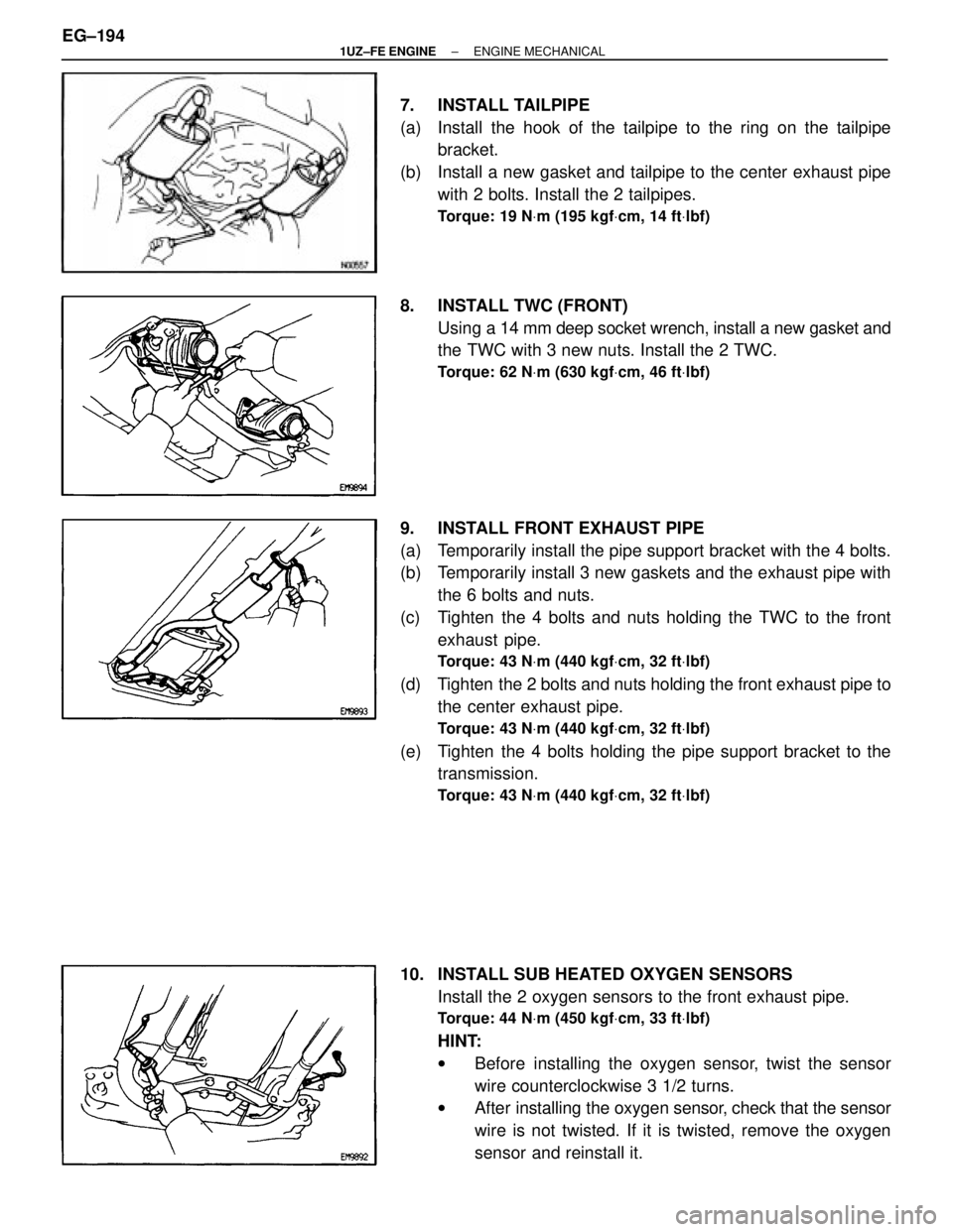
7. INSTALL TAILPIPE
(a) Install the hook of the tailpipe to the ring on the tailpipebracket.
(b) Install a new gasket and tailpipe to the center exhaust pipe with 2 bolts. Install the 2 tailpipes.
Torque: 19 N Vm (195 kgf Vcm, 14 ft Vlbf)
8. INSTALL TWC (FRONT)
Using a 14 mm deep socket wrench, install a new gasket and
the TWC with 3 new nuts. Install the 2 TWC.
Torque: 62 N Vm (630 kgf Vcm, 46 ft Vlbf)
9. INSTALL FRONT EXHAUST PIPE
(a) Temporarily install the pipe support bracket with the 4 bolts.
(b) Temporarily install 3 new gaskets and the exhaust pipe with
the 6 bolts and nuts.
(c) Tighten the 4 bolts and nuts holding the TWC to the front exhaust pipe.
Torque: 43 N Vm (440 kgf Vcm, 32 ft Vlbf)
(d) Tighten the 2 bolts and nuts holding the front exhaust pipe to
the center exhaust pipe.
Torque: 43 N Vm (440 kgf Vcm, 32 ft Vlbf)
(e) Tighten the 4 bolts holding the pipe support bracket to the
transmission.
Torque: 43 N Vm (440 kgf Vcm, 32 ft Vlbf)
10. INSTALL SUB HEATED OXYGEN SENSORS
Install the 2 oxygen sensors to the front exhaust pipe.
Torque: 44 N Vm (450 kgf Vcm, 33 ft Vlbf)
HINT:
w Before installing the oxygen sensor, twist the sensor
wire counterclockwise 3 1/2 turns.
w After installing the oxygen sensor, check that the sensor
wire is not twisted. If it is twisted, remove the oxygen
sensor and reinstall it.
EG±194
±
1UZ±FE ENGINE ENGINE MECHANICAL
WhereEverybodyKnowsYourName
Page 1591 of 4087
(i) Remove the bolt holding the engine wire clamp to theheater water valve bracket.
(j) Remove the two bolts holding the engine wire clamp to the body.
(k) Pull out the engine wire from the cabin.
28. REMOVE FRONT EXHAUST PIPE (a) Disconnect the grommet from the floor, and disconnectthe sub±oxygen sensor from the exhaust pipe.
Disconnect the two sub±oxygen sensors.
(b) Remove the four bolts holding the front exhaust pipe to the transmission.
(c) Remove the two bolts and nuts holding the front exhaust
pipe to the center exhaust pipe.
(d) Re mo ve th e fo u r bo lts an d nu ts ho ld in g th e fro n t
exhaust pipe to the catalytic converter. Remove the pipe
support stay, front exhaust pipe and three gaskets.
29. REMOVE CATALYTIC CONVERTERS (MAIN) Remove the three nuts, catalytic converter and gasket. Re-
move the two catalytic converters.
EM±126
±
ENGINE MECHANICAL Cylinder Block
WhereEverybodyKnowsYourName
Page 1634 of 4087

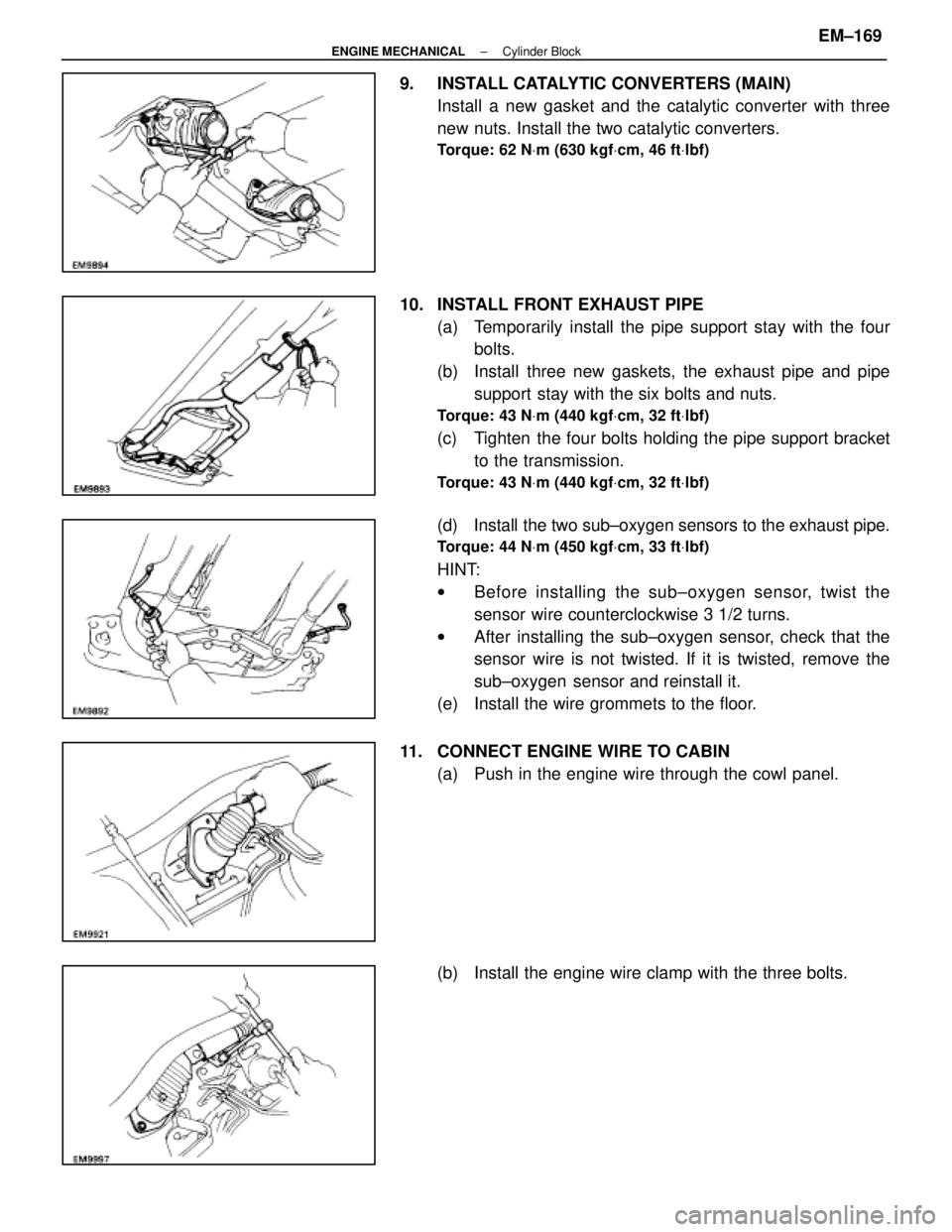
9. INSTALL CATALYTIC CONVERTERS (MAIN)Install a new gasket and the catalytic converter with three
new nuts. Install the two catalytic converters.
Torque: 62 N Vm (630 kgf Vcm, 46 ft Vlbf)
10. INSTALL FRONT EXHAUST PIPE
(a) Temporarily install the pipe support stay with the fourbolts.
(b) Install three new gaskets, the exhaust pipe and pipe support stay with the six bolts and nuts.
Torque: 43 N Vm (440 kgf Vcm, 32 ft Vlbf)
(c) Tighten the four bolts holding the pipe support bracket
to the transmission.
Torque: 43 N Vm (440 kgf Vcm, 32 ft Vlbf)
(d) Install the two sub±oxygen sensors to the exhaust pipe.
Torque: 44 N Vm (450 kgf Vcm, 33 ft Vlbf)
HINT:
w Before installing the s ub±oxygen sensor, twist the
sensor wire counterclockwise 3 1/2 turns.
w After installing the sub±oxygen sensor, check that the
sensor wire is not twisted. If it is twisted, remove the
sub±oxygen sensor and reinstall it.
(e) Install the wire grommets to the floor.
11. CONNECT ENGINE WIRE TO CABIN (a) Push in the engine wire through the cowl panel.
(b) Install the engine wire clamp with the three bolts.
±
ENGINE MECHANICAL Cylinder BlockEM±169
WhereEverybodyKnowsYourName