Page 2494 of 4087

Warm up the oxygen sensors with the engine at 2,500 rpm for
approx. 120 seconds.
Connect terminals TE1 and E1 of the check connector.
And maintain engine at 2,500 rpm.
Check the number of times the voltmeter needle fluctuates in 10 seconds.\
Warm up the oxygen sensors with the engine at 2,500 rpm.
for approx. 120 seconds. And maintain engine at 2,500 rpm.
Check the number of times the voltmeter needle
fluctuates in 10 seconds.
Disconnect terminals TE1 and E1 of the check connector.
And maintain engine at 2,500 rpm.
Measure voltage between terminals VF1 (VF2) and E1.Replace the ECU.
Normal
Measure voltage between terminals VF1 (VF2) and E1.
Read and record diagnostic codes. (See TR Section)
Disconnect terminals TE1 and E1 of the check connector.
And maintain engine at 2,500 rpm. Repair the relevant diagnostic code. Repair the relevant diagnostic code.
Normal code, code Nos.
21, 25 and 26
Malfunction code(s)
(Ex. code Nos. 21, 25 and 26)
Malfunction code(s)
(Ex. code Nos. 21, 25 and 26)Normal code, code Nos.
21, 25 and 26
More than 0 V
0 V
Less than 8 times
Less than 8 times
8 times or more
8 times
or more
Zero
Zero
Zero again After replacing
the oxygen sensor
CONTINUED ON PAGE FI±115
FI±114
EFI SYSTEM
± Electronic Control System (Main Oxygen Sensors)
WhereEverybodyKnowsYourName
Page 2495 of 4087
Disconnect terminals TE1 and E1 of the check connector.
And maintain engine at 2,500 rpm.
Repair (Over rich)
Replace the oxygen sensor.Repair (Over rich)
Measure voltage between terminals VF1 (VF2) and E1.
Disconnect the PCV hose.
Measure voltage between terminals VF1 (VF2) and E1.
Disconnect the water temp. sensor connector and connect
resistor with a resistance of 4 ± 8 k
� or another coded water
temp. sensor.
Connect terminals TE1 and E1 of the check connector.
Warm up the oxygen sensors with the engine at 2,500 rpm for
approx. 120 seconds. and maintain engine at 2,500 rpm.
Measure voltage between terminals VF1 (VF2) and E1.
5 V
CONTINUED FROM PAGE FI±114
0 V
0 V
0 V5 V
More than 0 V
FI±115EFI SYSTEM ± Electronic Control System (Main Oxygen Sensors)
WhereEverybodyKnowsYourName
Page 2496 of 4087
3. DISCONNECT CABLE FROM NEGATIVE TERMINAL OFBATTERY
CAUTION: Work must be started after approx. 20 se-
conds or longer from the time the ignition switch is
turned to the ºLOCKº position and the negative (±) termi-
nal cable is disconnected from the battery.
4. INSPECT HEATER RESIST ANCE OF MAIN OXYGEN
SENSORS
(a) Disconnect the oxygen sensor connectors.
(b) Using an ohmmeter, measure the resistance between the terminals +B and HT.
Resistance: 5.1±6.3 � at 20 °C (68 °F)
If the resistance is not as specified, replace the sensor.
Torque: 44 N Vm (450 kgf Vcm, 33 ft Vlbf)
(c) Reconnect the oxygen sensor connectors.
5. RECONNECT CABLE TO NEGATIVE TERMINAL OF BATTERY
FI±116
EFI SYSTEM
± Electronic Control System (Main Oxygen Sensors)
WhereEverybodyKnowsYourName
Page 2497 of 4087
Sub±Oxygen Sensors
COMPONENTS FOR REMOVAL AND
INSTALLATION
FI±117 ± Electronic Control System (Sub±Oxygen\
Sensors)EFI SYSTEM
WhereEverybodyKnowsYourName
Page 2498 of 4087
 Cancel diagnostic code. (See TR section)
(b) A llo w th e en g in e to wa rm up to no rma l op e ra tin gtemperature.
(c) Drive")
INSPECTION OF SUB±OXYGEN
SENSORS
1. INSPECT SUB±OXYGEN SENSORS(a) Cancel diagnostic code. (See TR section)
(b) A llo w th e en g in e to wa rm up to no rma l op e ra tin gtemperature.
(c) Drive for 5 minutes or more between 80km/h (50 mph) and 100 km/h (62 mph) in ºDº range.
(d) Following the conditions in step (c), press fully on the accelerator pedal for 2 seconds or more.
HINT: Do not exceed 100 km/h (62 mph), or diagnostic code
will be cancelled.
(e) Stop the vehicle, and turn the ignition switch to OFF.
(f) Carry out steps (b), (c) and (d) again to test acceleration.
If code No.27 reappears again, check the sub±oxygen sen-
sor circuit. If the circuit is normal, replace the sub±oxygen
sensor.
2. DISCONNECT CABLE FROM NEGATIVE TERMINAL OF BATTERY
CAUTION: Work must be started after approx. 20 se-
conds or longer from the time the ignition switch is
turned to the ºLOCKº position and the negative (±) termi-
nal cable is disconnected from the battery.
3. REMOVE TRANSMISSION SHIFT LEVER KNOB (a) Push down the lever cover.
(b) Remove the two screws and shift lever knob.
(c) Remove the lever cover.
FI±118
EFI SYSTEM
± Electronic Control System (Sub±Oxygen Sensors)
WhereEverybodyKnowsYourName
Page 2499 of 4087
4. REMOVE CUP HOLDERUsing a screwdriver, pry out the rear side of the cup holder.
Remove the cup holder.
5. REMOVE UPPER REAR CONSOLE PANEL Using a screwdriver, pry out the console panel.
6. REMOVE UPPER CONSOLE PANEL (a) Remove the six mounting screws.
(b) Using a screwdriver, pry out the console panel.
7. REMOVE RADIO (a) Remove the five mounting bolts.
(b) Disconnect the wiring connectors and antenna cable,
and remove the radio.
8. DISCONNECT SUB±OXYGEN SENSOR CONNECTORS FI±119
EFI SYSTEM
± Electronic Control System (Sub±Oxygen Sensors)
WhereEverybodyKnowsYourName
Page 2500 of 4087
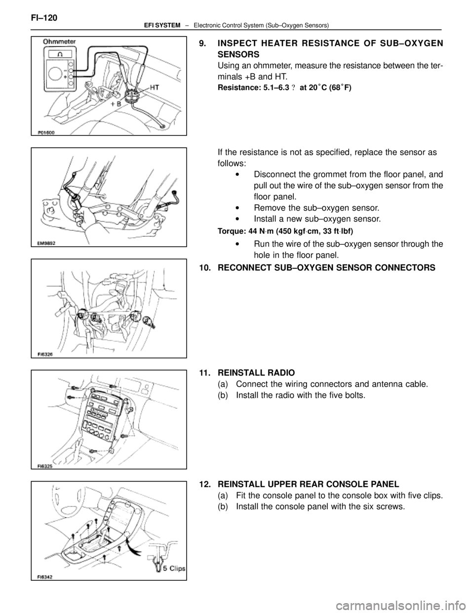
9. INSPECT HEATER RESISTANCE OF SUB±OXYGEN
SENSORS
Using an ohmmeter, measure the resistance between the ter-
minals +B and HT.
Resistance: 5.1±6.3 � at 20 °C (68 °F)
If the resistance is not as specified, replace the sensor as
follows:
w Disconnect the grommet from the floor panel, and
pull out the wire of the sub±oxygen sensor from the
floor panel.
w Remove the sub±oxygen sensor.
w Install a new sub±oxygen sensor.
Torque: 44 N Vm (450 kgf Vcm, 33 ft Vlbf)
w Run the wire of the sub±oxygen sensor through the
hole in the floor panel.
10. RECONNECT SUB±OXYGEN SENSOR CONNECTORS
11. REINSTALL RADIO (a) Connect the wiring connectors and antenna cable.
(b) Install the radio with the five bolts.
12. REINSTALL UPPER REAR CONSOLE PANEL (a) Fit the console panel to the console box with five clips.
(b) Install the console panel with the six screws.
FI±120
EFI SYSTEM
± Electronic Control System (Sub±Oxygen Sensors)
WhereEverybodyKnowsYourName
Page 2501 of 4087
13. REINSTALL UPPER CONSOLE PANELFit the console panel to the console box with the four clips.
14. REINSTALL CUP HOLDER Fit the cup holder to the console box.
15. REINSTALL TRANSMISSION SHIFT LEVER KNOB (a) Slide the lever cover on the lever shaft.
(b) Install the shift lever knob with the two screws.
(c) Attach the l ever cover to the lower side of the lever knob.
16. RECONNECT CABLE TO NEGATIVE TERMINAL OF BATTERY FI±121
EFI SYSTEM
± Electronic Control System (Sub±Oxygen Sensors)
WhereEverybodyKnowsYourName

Replace the oxygen sensor.Repair (Over rich)
Measure voltage between terminals VF1 (VF2) a")

EFI SYSTEM
WhereEverybodyKnowsYourName")