Page 2013 of 4087
ELECTRONIC CONTROL SYSTEM
The control system consists of sensors which detect various engine conditions, and a ECU which deter\
-
mines the injection volume (timing) based on the signals from the sens\
ors.
The various sensors detect the air intake volume, engine rpm, oxygen densit\
y in the exhaust gas, coolant
temperature, air intake temperature and atmospheric pressure etc. and convert the in\
formation into an electrical
signal which is sent to the ECU. Based on these signals, the ECU calculates th\
e optimum ignition timing for the
current conditions and operates the injectors.
The ECU not only controls the fuel injection timing, but also the self diag\
nostic function which records the
occurrence of a malfunction, ignition timing control, idle rpm control, \
EGR control, EVAP control, fuel pressure
control and fuel pump control. FI±9
EFI SYSTEM
± Operation
WhereEverybodyKnowsYourName
Page 2018 of 4087

PRECAUTIONS
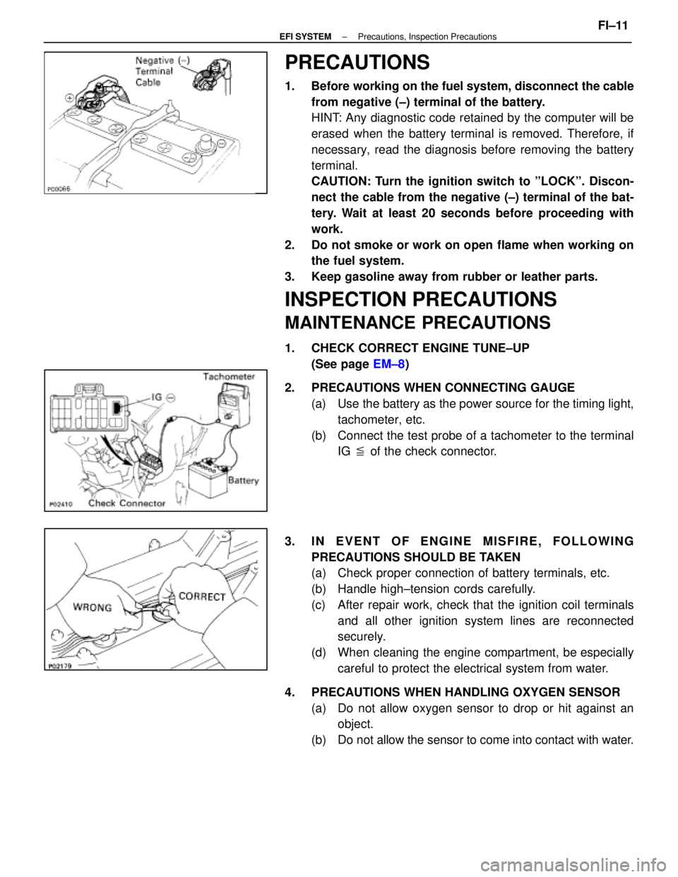
1. Before working on the fuel system, disconnect the cablefrom negative (±) terminal of the battery.
HINT: Any diagnostic code retained by the computer will be
erased when the battery terminal is removed. Therefore, if
necessary, read the diagnosis before removing the battery
terminal.
CAUTION: Turn the ignition switch to ºLOCKº. Discon-
nect the cable from the negative (±) terminal of the bat-
tery. Wait at least 20 seconds before proceeding with
work.
2. Do not smoke or work on open flame when working on the fuel system.
3. Keep gasoline away from rubber or leather parts.
INSPECTION PRECAUTIONS
MAINTENANCE PRECAUTIONS
1. CHECK CORRECT ENGINE TUNE±UP (See page EM±8)
2. PRECAUTIONS WHEN CONNECTING GAUGE (a) Use the battery as the power source for the timing light,tachometer, etc.
(b) Connect the test probe of a tachometer to the terminal IG � of the check connector.
3. IN EVENT OF ENGINE MISFIRE, FOLLOWING PRECAUTIONS SHOULD BE TAKEN
(a) Check proper connection of battery terminals, etc.
(b) Handle high±tension cords carefully.
(c) After repair work, check that the ignition coil terminalsand all other ignition system lines are reconnected
securely.
(d) When cleaning the engine compartment, be especially careful to protect the electrical system from water.
4. PRECAUTIONS WHEN HANDLING OXYGEN SENSOR (a) Do not allow oxygen sensor to drop or hit against anobject.
(b) Do not allow the sensor to come into contact with water.
±
EFI SYSTEM Precautions, Inspection PrecautionsFI±11
WhereEverybodyKnowsYourName
Page 2023 of 4087

PRECAUTIONS
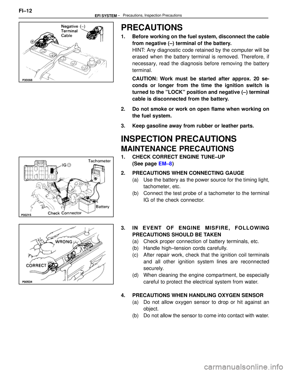
1. Before working on the fuel system, disconnect the cablefrom negative (±) terminal of the battery.
HINT: Any diagnostic code retained by the computer will be
erased when the battery terminal is removed. Therefore, if
necessary, read the diagnosis before removing the battery
terminal.
CAUTION: Work must be started after approx. 20 se-
conds or longer from the time the ignition switch is
turned to the ºLOCKº position and negative (±) terminal
cable is disconnected from the battery.
2. Do not smoke or work on open flame when working on the fuel system.
3. Keep gasoline away from rubber or leather parts.
INSPECTION PRECAUTIONS
MAINTENANCE PRECAUTIONS
1. CHECK CORRECT ENGINE TUNE±UP (See page EM±8)
2. PRECAUTIONS WHEN CONNECTING GAUGE (a) Use the battery as the power source for the timing light,tachometer, etc.
(b) Connect the test probe of a tachometer to the terminal IG of the check connector.
3. IN EVENT OF ENGINE MISFIRE, FOLLOWING PRECAUTIONS SHOULD BE TAKEN
(a) Check proper connection of battery terminals, etc.
(b) Handle high±tension cords carefully.
(c) After repair work, check that the ignition coil terminalsand all other ignition system lines are reconnected
securely.
(d) When cleaning the engine compartment, be especially careful to protect the electrical system from water.
4. PRECAUTIONS WHEN HANDLING OXYGEN SENSOR (a) Do not allow oxygen sensor to drop or hit against anobject.
(b) Do not allow the sensor to come into contact with water.
FI±12
± Precautions, Inspection PrecautionsEFI SYSTEM
WhereEverybodyKnowsYourName
Page 2130 of 4087

REMOVAL OF OIL PUMP
(See Components on page LU±8)
HINT: When repairing the oil pump, the oil pan and strainer
should be removed and cleaned.
1. REMOVE ENGINE WITH TRANSMISSION (See pages EM±118 to 128)
2. SEPARATE ENGINE AND TRANSMISSION (See pages EM±129 to 130)
3. INSTALL ENGINE TO ENGINE STAND FOR REMOVAL
4. REMOVE TIMING BELT (See steps 8 to 35 on pages EM±36 to 43)
5. REMOVE NO.2 IDLER PULLEY, NO.1 IDLER PULLEY AND CRANKSHAFT TIMING PULLEY
(See steps 36 to 38 on page EM±44)
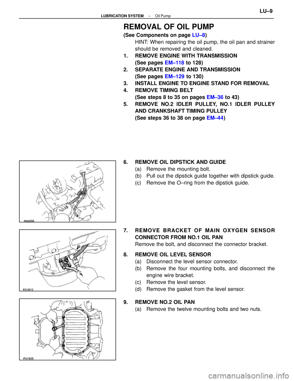
6. REMOVE OIL DIPSTICK AND GUIDE (a) Remove the mounting bolt.
(b) Pull out the dipstick guide together with dipstick guide.
(c) Remove the O±ring from the dipstick guide.
7. REMOVE BRACKET OF MAIN OXYGEN SENSOR CONNECTOR FROM NO.1 OIL PAN
Remove the bolt, and disconnect the connector bracket.
8. REMOVE OIL LEVEL SENSOR (a) Disconnect the level sensor connector.
(b) Remove the four mounting bolts, and disconnect theengine wire bracket.
(c) Remove the level sensor.
(d) Remove the gasket from the level sensor.
9. REMOVE NO.2 OIL PAN (a) Remove the twelve mounting bolts and two nuts.
±
LUBRICATION SYSTEM Oil PumpLU±9
WhereEverybodyKnowsYourName
Page 2140 of 4087

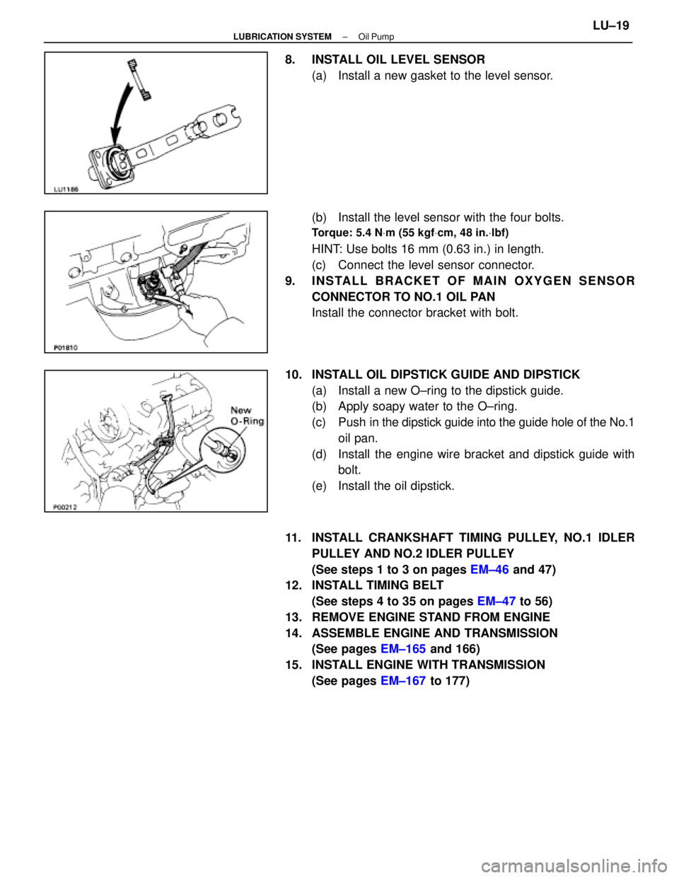
8. INSTALL OIL LEVEL SENSOR(a) Install a new gasket to the level sensor.
(b) Install the level sensor with the four bolts.
Torque: 5.4 N Vm (55 kgf Vcm, 48 in. Vlbf)
HINT: Use bolts 16 mm (0.63 in.) in length.
(c) Connect the level sensor connector.
9. INSTALL BRACKET OF MAIN OXYGEN SENSOR CONNECTOR TO NO.1 OIL PAN
Install the connector bracket with bolt.
10. INSTALL OIL DIPSTICK GUIDE AND DIPSTICK (a) Install a new O±ring to the dipstick guide.
(b) Apply soapy water to the O±ring.
(c) Push in the dipstick guide into the guide hole of the No.1
oil pan.
(d) Install the engine wire bracket and dipstick guide with bolt.
(e) Install the oil dipstick.
11. INSTALL CRANKSHAFT TIMING PULLEY, NO.1 IDLER PULLEY AND NO.2 IDLER PULLEY
(See steps 1 to 3 on pages EM±46 and 47)
12. INSTALL TIMING BELT
(See steps 4 to 35 on pages EM±47 to 56)
13. REMOVE ENGINE STAND FROM ENGINE
14. ASSEMBLE ENGINE AND TRANSMISSION (See pages EM±165 and 166)
15. INSTALL ENGINE WITH TRANSMISSION (See pages EM±167 to 177)
±
LUBRICATION SYSTEM Oil PumpLU±19
WhereEverybodyKnowsYourName
Page 2178 of 4087
PROPELLER SHAFT REMOVAL
PR02Q±06
1. REMOVE EXHAUST FRONT PIPE
(a) Disconnect the oxygen sensor grommets from the floor.
(b) Disconnect the oxygen sensors from the exhaust front pipe.
(c) Remove the 6 nuts, bolts and exhaust center pipe.
2. REMOVE EXHAUST CENTER PIPEHINT: To prevent interference, of the tail pipes must be sus-
pended from the stabilizer bar.
(a) Disconnect the exhaust center pipe from the 2 rings.
(b) Remove the 4 nuts.
(c) Remove the exhaust center pipe.
3. REMOVE HEAT INSULATOR Remove the 4 nuts and the heat insulator.
4. REMOVE CROSSMEMBER BRACE Remove the 4 bolts and the center floor crossmember brace.
PR±6
±
PROPELLER SHAFT PROPELLER SHAFT
WhereEverybodyKnowsYourName
Page 2186 of 4087
4. INSTALL HEAT INSULATORInstall the heat insulator and torque the 4 nuts.
Torque: 5.4 N Vm (55 kgf Vcm, 48 in. Vlbf)
5. INSTALL EXHAUST CENTER PIPE
(a) Install new gaskets.
(b) Install the exhaust center pipe.
(c) Install the exhaust center pipe to the 2 rings.
(d) Install and torque the new 4 nuts.
Torque: 19 N Vm (195 kgf Vcm, 14 ft Vlbf)
6. INSTALL EXHAUST FRONT PIPE
(a) Install new gaskets.
(b) Install the front pipe.
(c) Install and torque the 6 bolts and new nuts.
Torque: 43 N Vm (440 kgf Vcm, 32 ft Vlbf)
(d) Connect both oxygen sensors.
HINT: When connecting the oxygen sensor, turn it to the left
about 3 times.
NOTICE: After installing the oxygen sensor, check that
the wire is not twisted.
(e) Tighten the oxygen sensors.
Torque: 44 N Vm (450 kgf Vcm, 33 ft Vlbf)
(f) Connect the oxygen sensor grommets to the floor.
PR±14
±
PROPELLER SHAFT PROPELLER SHAFT
WhereEverybodyKnowsYourName
Page 2196 of 4087
PROPELLER SHAFT REMOVAL
PR030±02
1. REMOVE EXHAUST FRONT PIPE
(a) Disconnect the oxygen sensor grommets from the floor.
(b) Disconnect the oxygen sensors and heat insulator.
(c) Remove the 4 nuts, boolts and exhaust front pipe.
2. REMOVE EXHAUST CENTER PIPEHINT: To prevent interference of the tail pipe from with the
rear bumper, the front side of the tail pipe is suspended from
the stabilizer bar.
(a) Disconnect the exhaust center pipe from the 2 rings.
(b) Remove the 4 nuts and exhaust center pipe.
3. REMOVE HEAT INSULATOR Remove the 4 nuts and the heat insulator.
4. REMOVE CROSSMEMBER BRACE Remove the 4 bolts and the center floor crossmember brace.
PR±24
±
PROPELLER SHAFT PROPELLER SHAFT
WhereEverybodyKnowsYourName