Page 2203 of 4087
6. INSTALL EXHAUST FRONT PIPE
(a) Install new gaskets.
(b) Install the front pipe.
(c) Install and torque the 4 bolts and new nuts.
Torque: 43 NVm (440 kgf Vcm, 32 ft Vlbf)
(d) Connect both oxygen sensor with heat insulator.
HINT: When connecting the oxygen sensor, turn it clockwise
about 3 times.
NOTICE: After installing the oxygen sensor, check that
the wire is not twisted.
(e) Tighten the oxygen sensors.
Torque: 44 N Vm (450 kgf Vcm, 33 ft Vlbf)
(f) Connect the oxygen sensor grommets to the floor.
±
PROPELLER SHAFT PROPELLER SHAFTPR±31
WhereEverybodyKnowsYourName
Page 2229 of 4087

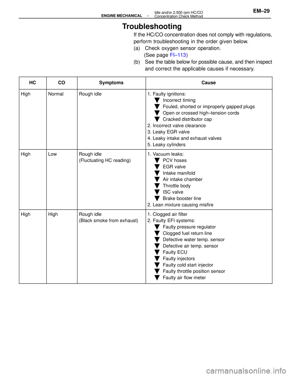
Troubleshooting
If the HC/CO concentration does not comply with regulations,
perform troubleshooting in the order given below.
(a) Check oxygen sensor operation.(See page FI±113)
(b) See the table below for possible cause, and then inspect
and correct the applicable causes if necessary.
����� �
����
�����HC����� �
����
�����CO���������� �
���������
����������Symptoms������������������\
� �
������������������
������������������\
�Cause
����� �����High����� �����Normal���������� ����������Rough idle������������������\
� ������������������\
�1. Faulty ignitions:
����� ���������� ��������������� ����������������������������\
� ������������������\
��Incorrect timing
����� ���������� ��������������� ����������������������������\
� ������������������\
��Fouled, shorted or improperly gapped plugs
����� ���������� ��������������� ����������������������������\
� ������������������\
��Open or crossed high±tension cords
Ckddiib��������������������������������������\
��Cracked distributor cap
Ill����� ���������� ��������������� ����������������������������\
� ������������������\
�2. Incorrect valve clearance
3 L k EGR l����� ���������� ��������������� ����������������������������\
� ������������������\
�3. Leaky EGR valve
4L k i k d h l����� ���������� ��������������� ����������������������������\
� ������������������\
�4. Leaky intake and exhaust valves
L k li d����� ���������� ��������������� ����������������������������\
� ������������������\
�5. Leaky cylinders
����� �����High����� �����Low���������� ����������Rough idle������������������\
� ������������������\
�1. Vacuum leaks:
����� ���������� ��������������� ����������(Fluctuating HC reading)������������������\
� ������������������\
��PCV hoses
����� ���������� ��������������� ����������������������������\
� ������������������\
��EGR valve
����� ���������� ��������������� ����������������������������\
� ������������������\
��Intake manifold
Ai i k h b����� ���������� ��������������� ����������������������������\
� ������������������\
��Air intake chamber
Th l b d����� ���������� ��������������� ����������������������������\
� ������������������\
��Throttle body
ISC l��������������������������������������\
��ISC valve
Bkb li����� ���������� ��������������� ����������������������������\
� ������������������\
��Brake booster line
2L i i ifi����� ���������� ��������������� ����������������������������\
� ������������������\
�2. Lean mixture causing misfire
����� �����High����� �����High���������� ����������Rough idle������������������\
� ������������������\
�1. Clogged air filter����� �����g����� �����g���������� ����������g
(Black smoke from exhaust)������������������\
� ������������������\
�gg
2. Faulty EFI systems:����� ���������� ��������������� ����������()������������������\
� ������������������\
�yy
�Faulty pressure regulator
����� ���������� ��������������� ����������������������������\
� ������������������\
�
yg
�Clogged fuel return line
����� ���������� ��������������� ����������������������������\
� ������������������\
�
gg
�Defective water temp. sensor
����� ���������� ��������������� ����������������������������\
� ������������������\
��Defective air temp. sensor
����� ���������� ��������������� ����������������������������\
� ������������������\
��Faulty ECU
����� ���������� ��������������� ����������������������������\
� ������������������\
�
y
�Faulty injectors
��������������������������������������\
�
yj
�Faulty cold start injector����� ���������� ��������������� ����������������������������\
� ������������������\
�yj
�Faulty throttle position sensor����� ���������� ��������������� ����������������������������\
� ������������������\
��Faulty air flow meter
±
ENGINE MECHANICAL Idle and/or 2,500 rpm HC/CO
Concentration Check MethodEM±29
WhereEverybodyKnowsYourName
Page 2274 of 4087
(e) Remove the following parts:(1) Wave washer
(2) Camshaft sub±gear
(3) Camshaft gear spring
HINT: Arrange the camshaft sub±gears and gear springs (RH
side and LH side).
43. REMOVE CIRCULAR PLUGS Remove the two bolts, seal washers, bearing cap and circular
plug. Remove the two circular plugs.
HINT: Arrange the bearing caps (RH side and LH side).
44. DISCONNECT MAIN OXYGEN SENSOR CONNECTORS Disconnect the RH and LH oxygen sensor connector.
EM±74
±
ENGINE MECHANICAL Cylinder Heads
WhereEverybodyKnowsYourName
Page 2275 of 4087
45. REMOVE CYLINDER HEADS(a) Uniformly loosen the ten cylinder head bolts on one side
of each cylinder head in several passes in the sequence
shown, then do the other side as shown. Remove the
twenty cylinder head bolts and plate washers.
NOTICE: Head warpage or cracking could result from re-
moving bolts in an incorrect order.
(b) Lift the cylinder heads from the dowels on the cylinder block, and place the two cylinder heads on wooden
blocks on a bench.
HINT: If the cylinder head is difficult to lift off, pry between the
cylinder head and cylinder block with a screwdriver.
NOTICE: Be careful not to damage the contact surfaces
of the cylinder head and cylinder block.
46. REMOVE EXHAUST MANIFOLD FROM RH CYLINDER HEAD
(a) Remove the three bolts and heat insulator.
(b) Remove the main oxygen sensor.
±
ENGINE MECHANICAL Cylinder HeadsEM±75
WhereEverybodyKnowsYourName
Page 2276 of 4087
(c) Remove the eight nuts, exhaust manifold and gasket.
47. REMOVE EXHAUST MANIFOLD FROM LH CYLINDER HEAD
(a) Remove the three bolts and heat insulator.
(b) Remove the main oxygen sensor.
(c) Remove the eight nuts, exhaust manifold and gasket.
DISASSEMBLY OF CYLINDER HEADS
(See Components on page EM±59)
1. REMOVE VALVE LIFTERS AND ADJUSTING SHIMS
EM±76
±
ENGINE MECHANICAL Cylinder Heads
WhereEverybodyKnowsYourName
Page 2291 of 4087
INSTALLATION OF CYLINDER HEADS
(See Components on pages EM±58 and 59)
1. INSTALL RH EXHAUST MANIFOLD TO RH CYLINDER HEAD
(a) Place a new gasket on the cylinder head with the white
painted marks facing the manifold side.
NOTICE: Be careful of the installation direction.
(b) Install the exhaust manifold with the eight new nuts. Uniformly tighten the nuts in several passes.
Torque: 39 N Vm (400 kgf Vcm, 29 ft Vlbf)
(c) Install the main oxygen sensor.
Torque: 44 N Vm (450 kgf Vcm, 33 ft Vlbf)
(d) Install the heat insulator with the three bolts.
2. INSTALL LH EXHAUST MANIFOLD TO LH CYLINDER HEAD
(a) Place a new gasket on the cylinder head with the whitepainted marks facing the manifold side.
NOTICE: Be careful of the installation direction.
±
ENGINE MECHANICAL Cylinder HeadsEM±91
WhereEverybodyKnowsYourName
Page 2292 of 4087
(b) Install the exhaust manifold with the eight new nuts.Uniformly tighten the nuts in several passes.
Torque: 39 N Vm (400 kgf Vcm, 29 ft Vlbf)
(c) Install the main oxygen sensor.
Torque: 44 N Vm (450 kgf Vcm, 33 ft Vlbf)
(d) Install the heat insulator with the three bolts.
3. INSTALL CYLINDER HEADS
A. Place cylinder heads on cylinder block (a) Place two new cylinder head gaskets in position on thecylinder block.
HINT: On the rear side of the cylinder head gasket are
painted marks to distinguish the LH and RH banks, a white
painted mark for the RH bank and a yellow painted mark for
the LH bank.
NOTICE: Be careful of the installation direction.
(b) Place the two cylinder heads in position on the cylinder
head gaskets.
EM±92
±
ENGINE MECHANICAL Cylinder Heads
WhereEverybodyKnowsYourName
Page 2293 of 4087

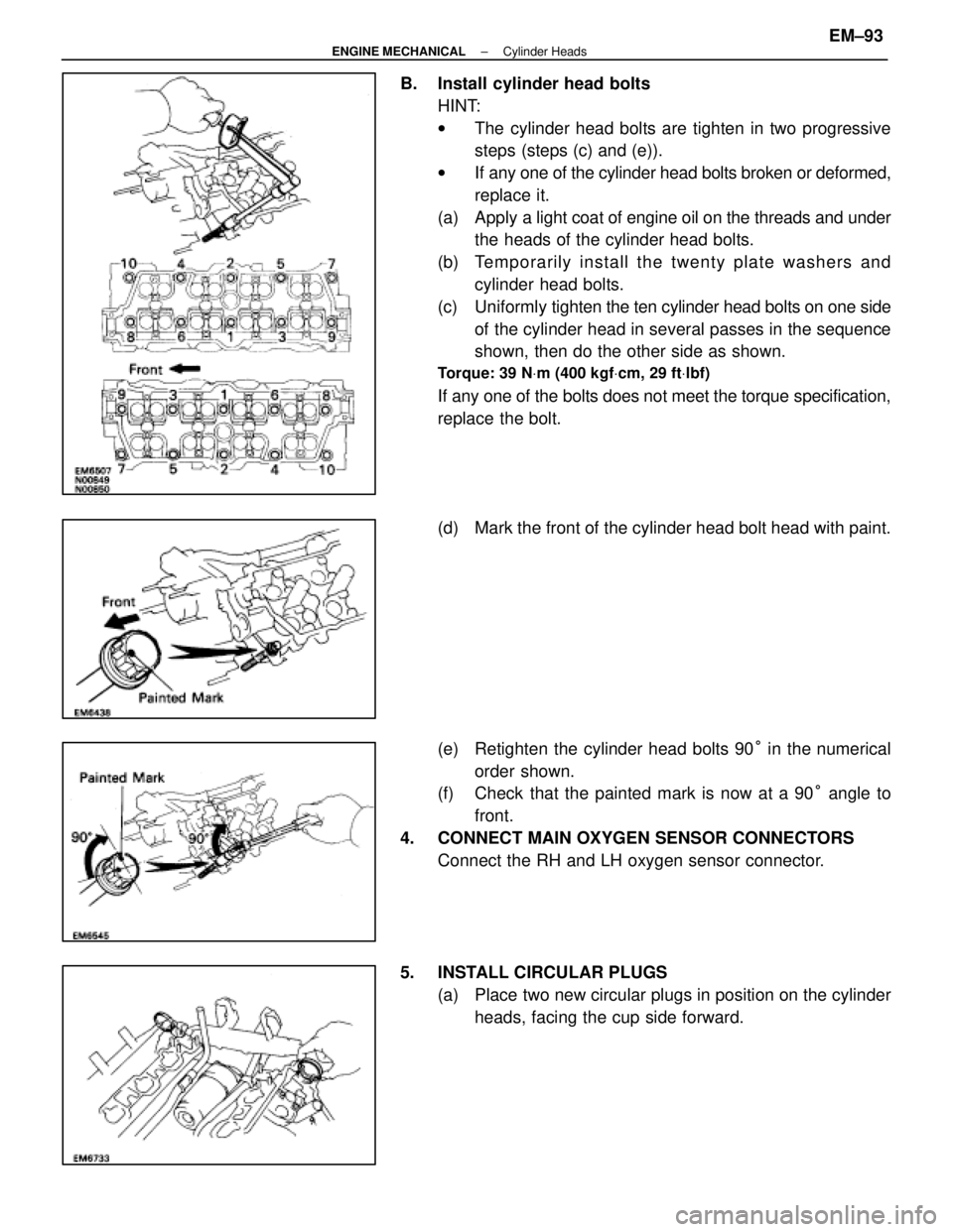
B. Install cylinder head boltsHINT:
wThe cylinder head bolts are tighten in two progressive
steps (steps (c) and (e)).
w If any one of the cylinder head bolts broken or deformed,
replace it.
(a) Apply a light coat of engine oil on the threads and under
the heads of the cylinder head bolts.
(b) Te mp o ra rily in sta ll th e twe n ty pla te wa sh e rs an d cylinder head bolts.
(c) Uniformly tighten the ten cylinder head bolts on one side
of the cylinder head in several passes in the sequence
shown, then do the other side as shown.
Torque: 39 N Vm (400 kgf Vcm, 29 ft Vlbf)
If any one of the bolts does not meet the torque specification,
replace the bolt.
(d) Mark the front of the cylinder head bolt head with paint.
(e) Retighten the cylinder head bolts 90 ° in the numerical
order shown.
(f) Check that the painted mark is now at a 90 ° angle to
front.
4. CONNECT MAIN OXYGEN SENSOR CONNECTORS Connect the RH and LH oxygen sensor connector.
5. INSTALL CIRCULAR PLUGS (a) Place two new circular plugs in position on the cylinderheads, facing the cup side forward.
±
ENGINE MECHANICAL Cylinder HeadsEM±93
WhereEverybodyKnowsYourName