Page 1591 of 4087
(i) Remove the bolt holding the engine wire clamp to theheater water valve bracket.
(j) Remove the two bolts holding the engine wire clamp to the body.
(k) Pull out the engine wire from the cabin.
28. REMOVE FRONT EXHAUST PIPE (a) Disconnect the grommet from the floor, and disconnectthe sub±oxygen sensor from the exhaust pipe.
Disconnect the two sub±oxygen sensors.
(b) Remove the four bolts holding the front exhaust pipe to the transmission.
(c) Remove the two bolts and nuts holding the front exhaust
pipe to the center exhaust pipe.
(d) Re mo ve th e fo u r bo lts an d nu ts ho ld in g th e fro n t
exhaust pipe to the catalytic converter. Remove the pipe
support stay, front exhaust pipe and three gaskets.
29. REMOVE CATALYTIC CONVERTERS (MAIN) Remove the three nuts, catalytic converter and gasket. Re-
move the two catalytic converters.
EM±126
±
ENGINE MECHANICAL Cylinder Block
WhereEverybodyKnowsYourName
Page 1636 of 4087
(g) Install the scuff plate.
(h) Connect the connectors.
(i) Install the lower instrument panel finish panel and glovecompartment door assembly with the four screws.
(j) Install the instrument panel under cover with the two clips.
12. INSTALL CHARCOAL CANISTER (a) Install the charcoal canister.
(b) Connect the vacuum hose and air hose to the charcoalcanister.
13. CONNECT HOSES Connect the following hose and ground strap:(1) Heater water hose to water by±pass pipe
(2) Heater water hose to heater water valve
(3) Vacuum hose to brake booster union on air intake
chamber
(4) Vacuum hose (from VSV for heater water valve) to
air intake chamber
(5) Ground strap to bracket on body
±
ENGINE MECHANICAL Cylinder BlockEM±171
WhereEverybodyKnowsYourName
Page 1672 of 4087

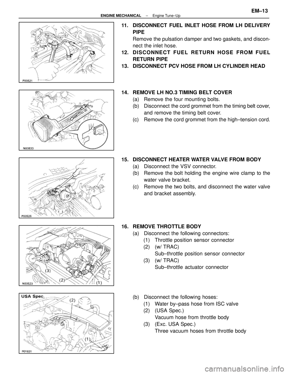
11. DISCONNECT FUEL INLET HOSE FROM LH DELIVERYPIPE
Remove the pulsation damper and two gaskets, and discon-
nect the inlet hose.
12. D I S C O N N E C T F U E L R E T U R N H O S E F R O M F U E L RETURN PIPE
13. DISCONNECT PCV HOSE FROM LH CYLINDER HEAD
14. REMOVE LH NO.3 TIMING BELT COVER (a) Remove the four mounting bolts.
(b) Disconnect the cord grommet from the timing belt cover,
and remove the timing belt cover.
(c) Remove the cord grommet from the high±tension cord.
15. DISCONNECT HEATER WATER VALVE FROM BODY (a) Disconnect the VSV connector.
(b) Remove the bolt holding the engine wire clamp to thewater valve bracket.
(c) Remove the two bolts, and disconnect the water valve and bracket assembly.
16. REMOVE THROTTLE BODY (a) Disconnect the following connectors:(1) Throttle position sensor connector
(2) (w/ TRAC)
Sub±throttle position sensor connector
(3) (w/ TRAC) Sub±throttle actuator connector
(b) Disconnect the following hoses: (1) Water by±pass hose from ISC valve
(2) (USA Spec.) Vacuum hose from throttle body
(3) (Exc. USA Spec.) Three vacuum hoses from throttle body
±
ENGINE MECHANICAL Engine Tune±UpEM±13
WhereEverybodyKnowsYourName
Page 1683 of 4087
(b) Install a new gasket and throttle body with the two boltsand two nuts.
Torque: 18 N Vm (185 kgf Vcm, 13 ft Vlbf)
HINT: Use bolts 40 mm (1.57 in.) in length.
(c) Install the water by±pass pipe (from rear water by±pass
joint) to the clamp on the engine wire cover.
(d) Connect the following hoses: (1) Water by±pass hose to the ISC valve
(2) (USA Spec.) Vacuum hose to throttle body
(3) (Exc. USA Spec.) Three vacuum hoses to throttle body
(e) Connect the following connectors: (1) Throttle position sensor connector
(2) (w/ TRAC) Sub±throttle position sensor connector
(3) (w/ TRAC) Sub±throttle actuator
27. REINSTALL HEATER WATER VALVE (a) Install the water valve and bracket assembly with thetwo bolts.
(b) Install the engine wire clamp with the bolt.
(c) Connect the VSV connector.
EM±24
±
ENGINE MECHANICAL Engine Tune±Up
WhereEverybodyKnowsYourName
Page 1700 of 4087
14. INSTALL NO. 2 AND NO. 3 TIMING BELT COVERS(a) Install the gasket on the timing belt cover.
(b) Using a 5 mm hexagon wrench, install the belt coverswith the nine bolts.
(c) Install the oil filler cap.
15. INSTALL RADIATOR AND WATER PUMP PULLEY (See steps 15, 16, 19 and 24 on pages EM±110 to 112)
16. FILL ENGINE WITH COOLANT (See page CO±5)
Capacity (w/ Heater):
M/T 8.5 liters (9.0 US qts, 7.5 Imp. qts)
A/T 8.4 liters (8.9 US qts, 7.4 Imp. qts)
17. (A/T)CHECK AUTOMATIC TRANSMISSION FLUID LEVEL
(See page MA±11)
NOTICE: Do not overfill.
18. START ENGINE AND CHECK FOR LEAKS
19. CHECK IGNITION TIMING (See page IG±14)
Ignition timing:
105 BTDC @ idle
(w/ Terminals TE1 and E1 connected)
20. PERFORM ROAD TEST Check for abnormal noise, shock, slippage, correct shift
points and smooth operation.
21. RECHECK ENGINE COOLANT LEVEL
±
ENGINE MECHANICAL Timing BeltEM±33
WhereEverybodyKnowsYourName
Page 1737 of 4087
(c) Uniformly loosen and remove the 12 bearing cap boltsin several passes in the sequence shown, and remove
the six bearing caps and camshaft. Remove the intake
and exhaust camshafts.
21. REMOVE CYLINDER HEAD (a) Using a 10 mm bi±hexagon wrench, uniformly loosenand remove the ten cylinder head bolts in several
passes in the sequence shown.
NOTICE: Cylinder head warpage or cranking could result
from removing in incorrect order.
(b) Remove the 14 plate washers.
(c) Lift the cylinder head from the dowels on the cylinder block. As the cylinder head is lifted, separate the heater
water hose from the union.
(d) Place the head on wooden blocks on a bench.
If the cylinder head is difficult to lift off, pry with a screwdriver
between the cylinder head and block projection.
NOTICE: Be careful not to damage the contact surfaces
of the cylinder head and cylinder block.
EM±40
±
ENGINE MECHANICAL Cylinder Head
WhereEverybodyKnowsYourName
Page 1749 of 4087

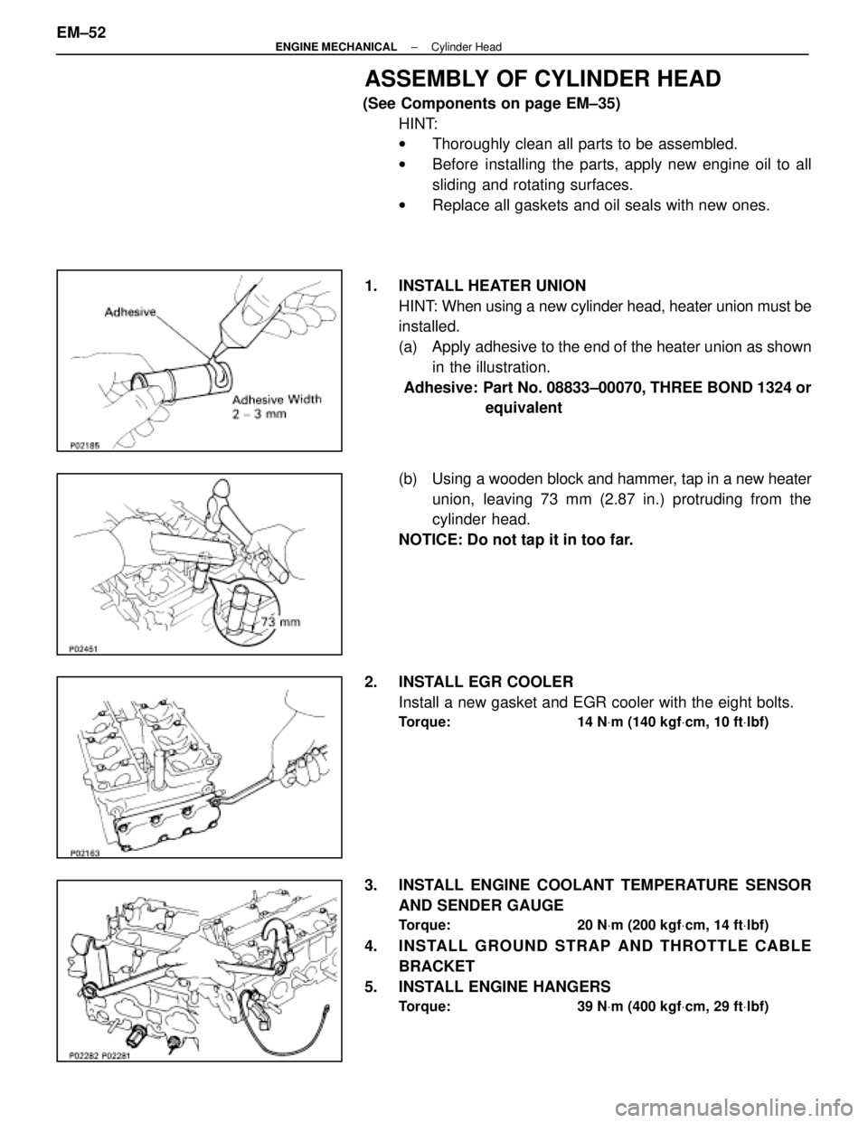
ASSEMBLY OF CYLINDER HEAD
(See Components on page EM±35)HINT:
wThoroughly clean all parts to be assembled.
w Before installing the parts, apply new engine oil to all
sliding and rotating surfaces.
w Replace all gaskets and oil seals with new ones.
1. INSTALL HEATER UNION HINT: When using a new cylinder head, heater union must be
installed.
(a) Apply adhesive to the end of the heater union as shownin the illustration.
Adhesive: Part No. 08833±00070, THREE BOND 1324 or equivalent
(b) Using a wooden block and hammer, tap in a new heater
union, leaving 73 mm (2.87 in.) protruding from the
cylinder head.
NOTICE: Do not tap it in too far.
2. INSTALL EGR COOLER Install a new gasket and EGR cooler with the eight bolts.
Torque: 14 N Vm (140 kgf Vcm, 10 ft Vlbf)
3. INSTALL ENGINE COOLANT TEMPERATURE SENSOR
AND SENDER GAUGE
Torque: 20 N Vm (200 kgf Vcm, 14 ft Vlbf)
4. INSTALL GROUND STRAP AND THROTTLE CABLE
BRACKET
5. INSTALL ENGINE HANGERS
Torque: 39 N Vm (400 kgf Vcm, 29 ft Vlbf)
EM±52±
ENGINE MECHANICAL Cylinder Head
WhereEverybodyKnowsYourName
Page 1751 of 4087

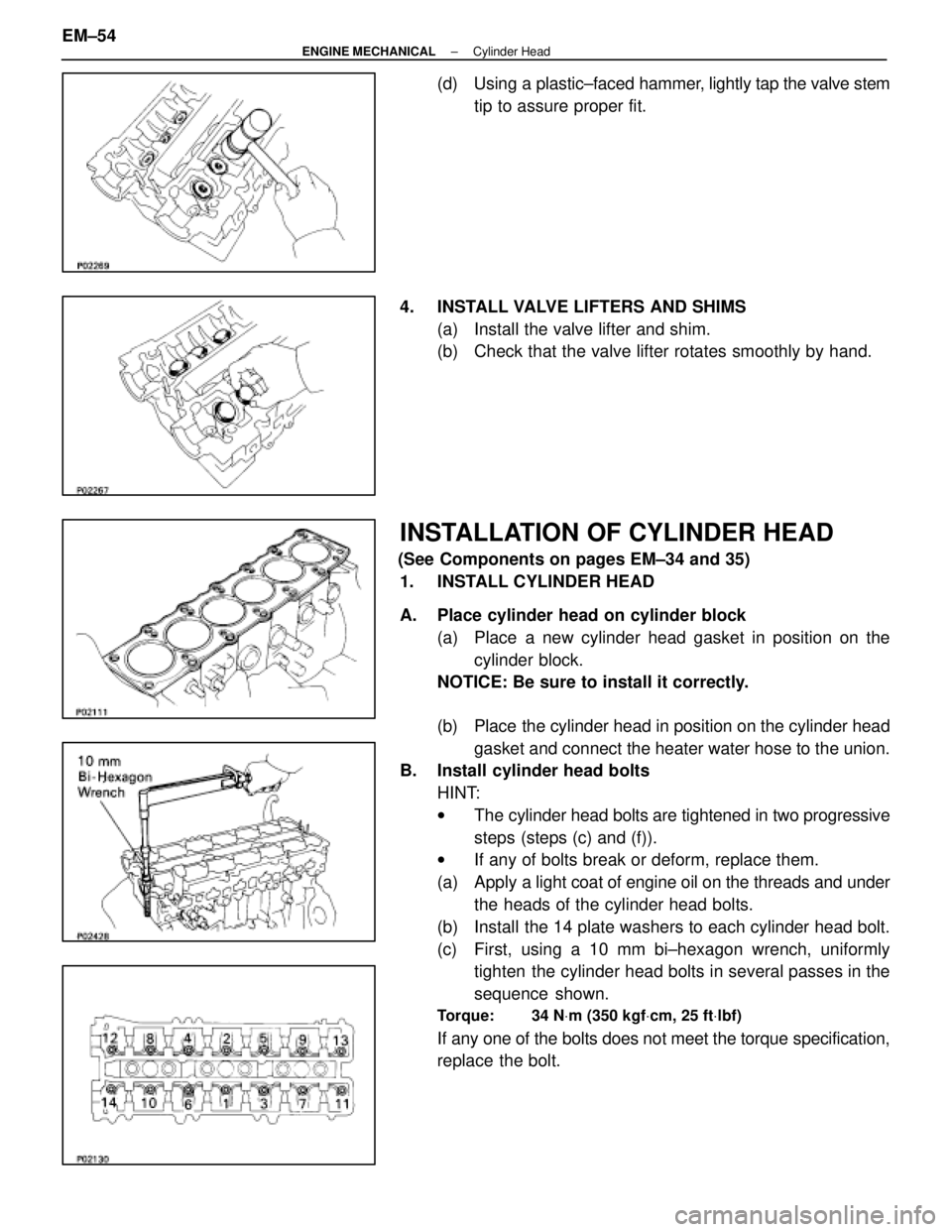
(d) Using a plastic±faced hammer, lightly tap the valve stem
tip to assure proper fit.
4. INSTALL VALVE LIFTERS AND SHIMS (a) Install the valve lifter and shim.
(b) Check that the valve lifter rotates smoothly by hand.
INSTALLATION OF CYLINDER HEAD
(See Components on pages EM±34 and 35)1. INSTALL CYLINDER HEAD
A. Place cylinder head on cylinder block (a) Place a new cylinder head gasket in position on thecylinder block.
NOTICE: Be sure to install it correctly.
(b) Place the cylinder head in position on the cylinder head
gasket and connect the heater water hose to the union.
B. Install cylinder head bolts
HINT:
wThe cylinder head bolts are tightened in two progressive
steps (steps (c) and (f)).
w If any of bolts break or deform, replace them.
(a) Apply a light coat of engine oil on the threads and under
the heads of the cylinder head bolts.
(b) Install the 14 plate washers to each cylinder head bolt.
(c) First, using a 10 mm bi±hexagon wrench, uniformly tighten the cylinder head bolts in several passes in the
sequence shown.
Torque: 34 N Vm (350 kgf Vcm, 25 ft Vlbf)
If any one of the bolts does not meet the torque specification,
replace the bolt.
EM±54
±
ENGINE MECHANICAL Cylinder Head
WhereEverybodyKnowsYourName