Page 1984 of 4087

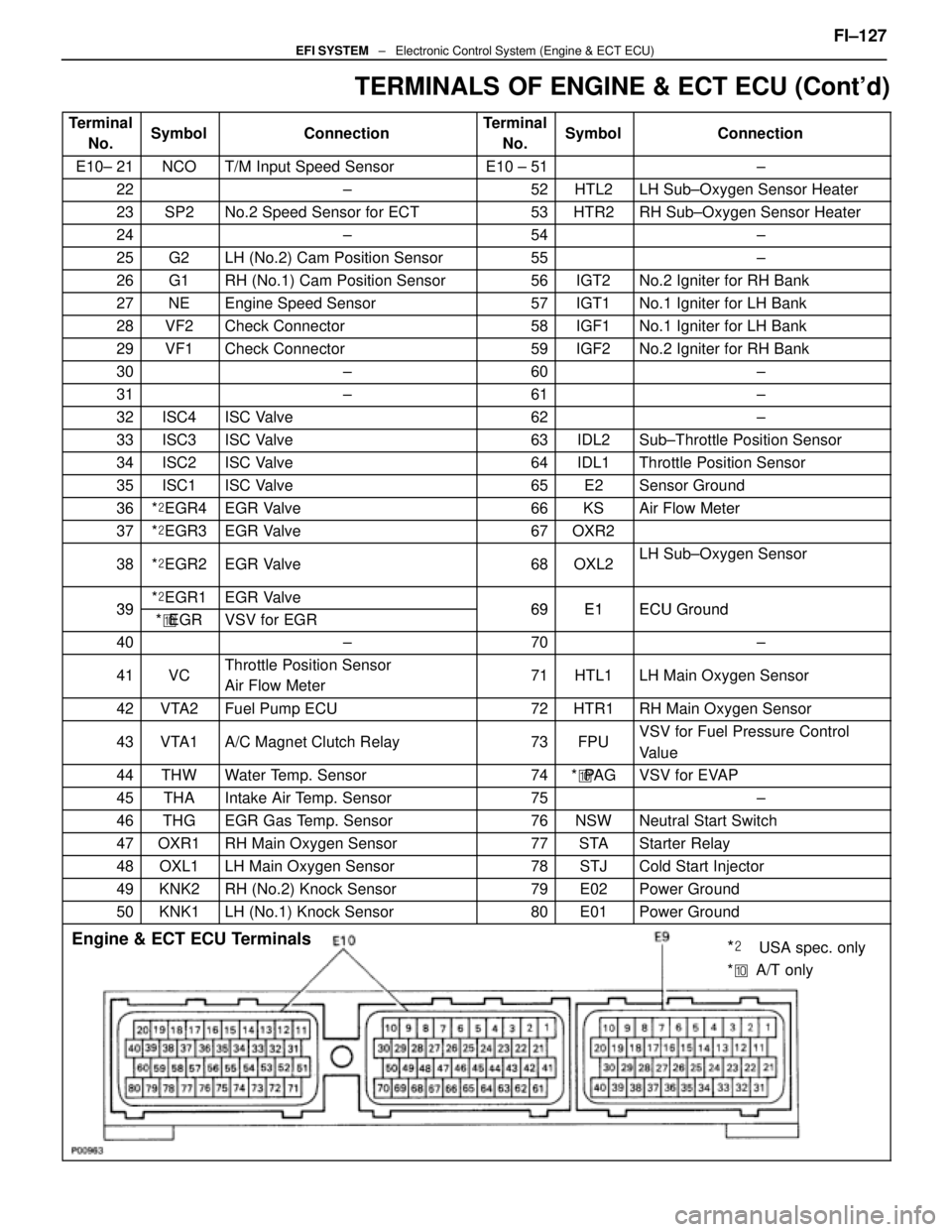
TERMINALS OF ENGINE & ECT ECU (Cont'd)
TerminalNo.SymbolConnectionTerminalNo.SymbolConnection
E10± 21NCOT/M Input Speed SensorE10 ± 51±
22±52HTL2LH Sub±Oxygen Sensor Heater
23SP2No.2 Speed Sensor for ECT53HTR2RH Sub±Oxygen Sensor Heater
24±54±
25G2LH (No.2) Cam Position Sensor55±
26G1RH (No.1) Cam Position Sensor56IGT2No.2 Igniter for RH Bank
27NEEngine Speed Sensor57IGT1No.1 Igniter for LH Bank
28VF2Check Connector58IGF1No.1 Igniter for LH Bank
29VF1Check Connector59IGF2No.2 Igniter for RH Bank
30±60±
31±61±
32ISC4ISC Valve62±
33ISC3ISC Valve63IDL2Sub±Throttle Position Sensor
34ISC2ISC Valve64IDL1Throttle Position Sensor
35ISC1ISC Valve65E2Sensor Ground
36*� EGR4EGR Valve66KSAir Flow Meter
37*� EGR3EGR Valve67OXR2
38*� EGR2EGR Valve68OXL2LH Sub±Oxygen Sensor
39*� EGR1EGR Valve69E1ECU Ground39*� EGRVSV for EGR69E1ECU Ground
40±70±
41VCThrottle Position Sensor
Air Flow Meter71HTL1LH Main Oxygen Sensor
42VTA2Fuel Pump ECU72HTR1RH Main Oxygen Sensor
43VTA1A/C Magnet Clutch Relay73FPUVSV for Fuel Pressure Control
Value
44THWWater Temp. Sensor74*� PA GVSV for EVAP
45THAIntake Air Temp. Sensor75±
46THGEGR Gas Temp. Sensor76NSWNeutral Start Switch
47OXR1RH Main Oxygen Sensor77STAStarter Relay
48OXL1LH Main Oxygen Sensor78STJCold Start Injector
49KNK2RH (No.2) Knock Sensor79E02Power Ground
50KNK1LH (No.1) Knock Sensor80E01Power Ground
Engine & ECT ECU Terminals
*��USA spec. only
* �� A/T only
FI±127EFI SYSTEM ± Electronic Control System (Engine & ECT ECU)
WhereEverybodyKnowsYourName
Page 1995 of 4087

SERVICE DATA (Cont'd)
Water temp.
sensorResistanceat ±20°C (±4 °F)
at 0 °C (32 °F)
at 20 °C (68 °F)
at 40 °C (104 °F)
at 60 °C (140 °F)
at 80 °C (176 °F)10 ± 20 k �
4 ± 7 k �
2 ± 7 k �
0.9 ± 1.3 k �
0.4 ± 0.7 k �
0.2 ± 0.4 k �
EGR gas
temp.
sensorResistanceat 50°C (112 °F)
at 100 °C (212 °F)
at 150 °C (302 °F)69 ± 89 k �
12 ± 15 k �
2 ± 4 k �
Main oxygen
sensorHeater coil resistance5.1 ± 6.3 �
Sub±oxygen
sensorHeater coil resistance5.1 ± 6.3 �
ECUHINT:
�Perform all voltage and resistance measurements with the ECU connected.
� Verify that the battery voltage in 11 V or above with the ignition switch is ON.
Voltage
TerminalsConditionSTD voltage (V)
BATT ± E1±10 ± 14
IGSW
+B ± E1
+B1
IG SW ON10 ± 14
VC ± E2±4.0 ± 6.0
IDL1E2
Throttle (or sub±throttle) valve fully closed1 or lessIDL1
IDL2 ± E2
IG SW ONThrottle (or sub±throttle) valve fully open10 ± 14
VTA1E2
Throttle (or sub±throttle) valve fully closed0.1 or lessVTA1
VTA 2 ± E2
Throttle (or sub±throttle) valve fully open3.0 ± 6.0
KS ± E1IdlingPulse generation
THA ± E2
THW±E2Idling
Intake air temp. 20
°C (68 °F)1.0 ± 3.0
THW ± E2IdlingEngine coolant temp. 80 °C (176 °F)0.1 ± 1.0
STA ± E1Cranking6.0 or more
#10
#20
E01IG SW ON10 ± 14#20
#30
#40±
E01
E02IdlingPulse generation
IGT1
IGT2
± E1IdlingPulse generation
FI±138EFI SYSTEM
± Service Specifications
WhereEverybodyKnowsYourName
Page 2050 of 4087
11. REMOVE LH NO.3 TIMING BELT COVER(a) Remove the four mounting bolts.
(b) Disconnect the cord grommet from the timing belt cover,
and remove the timing belt cover.
(c) Remove the cord grommet from the high±tension cord.
12. REMOVE LOWER HIGH±TENSION CORD COVER (a) Disconnect the high±tension cord from the RH ignitioncoil.
(b) D i s c onnect the high±tension cords from the
high±tension cord cover.
(c) Remove the bolt and cord cover.
13. REMOVE THROTTLE BODY (a) Disconnect the following connectors:(1) Throttle position sensor connector
(2) (w/ TRAC) Sub±throttle position sensor connector
(3) (w/ TRAC) Sub±throttle actuator connector
(b) Disconnect the following hoses: (1) Heater water hose from heater water valve FI±29
EFI SYSTEM
± Fuel System (Cold Start Injector)
WhereEverybodyKnowsYourName
Page 2052 of 4087
15. DISCONNECT HOSESDisconnect the following hoses:(1) Water by±pass hose (from water inlet housing) from ISC valve
(2) Vacuum hose (from PS air control valve) from air in-
take chamber
(3) Vacuum sensing hose (from fuel pressure regula- tor) from vacuum pipe
(4) Two vacuum hoses (from VSV for EVAP system) from vacuum pipe
(5) Vacuum hose (from charcoal canister) from vacu- um pipe
(6) Water by±pass hose (from EGR valve) from water by±pass pipe
(7) Vacuum hose (from brake booster) from air intake
chamber
(8) Vacuum hose (from VSV for heater water valve) from air intake chamber
(9) PCV hose from LH cylinder head cover
16. REMOVE AIR INTAKE CHAMBER (a) Remove the bolt, stud bolt and accelerator bracket. FI±31
EFI SYSTEM
± Fuel System (Cold Start Injector)
WhereEverybodyKnowsYourName
Page 2058 of 4087
(g) Install the accelerator bracket with the bolt and stud bolt.
3. CONNECT HOSES Connect the following hoses:(1) Water by±pass hose (from EGR valve) to water by±
pass pipe
(2) Vacuum hose (from brake booster) to air intake chamber
(3) Vacuum hose (from VSV for heater water valve) to
air intake chamber
(4) PCV hose to LH cylinder head cover
(5) Water by±pass hose (from water inlet housing) to ISC valve
(6) Vacuum hose (from PS air control valve) to air in- take chamber
(7) Vacuum sensing hose (from fuel pressure regula- tor) to vacuum pipe
(8) Two vacuum hoses (from VSV for EVAP system) to
vacuum pipe
(9) Vacuum hose (from charcoal canister) to vacuum pipe FI±37
EFI SYSTEM
± Fuel System (Cold Start Injector)
WhereEverybodyKnowsYourName
Page 2060 of 4087
(4) Heater water hose to heater water valve
(e) Connect the following connectors: (1) Throttle position sensor connector
(2) (w/ TRAC)
Sub±throttle position sensor connector
(3) (w/ TRAC) Sub±throttle actuator connector
5. INSTALL LOWER HIGH±TENSION CORD COVER (a) Connect the end portions of the high±tension cord to the
cord clamps
(b) Install the high±tension cord cover with the bolt.
(c) Install the clamps on the high±tension cords to the
high±tension cord cover.
(d) Connect the high±tension cord to the RH ignition coil.
7. INSTALL RH NO.3 TIMING BELT COVER (a) Install the three gaskets to the timing belt cover.
(b) Fit portion A of the timing belt cover, matching it with the
lower high±tension cord cover.
(c) Install the timing belt cover with the three bolts. FI±39
EFI SYSTEM
± Fuel System (Cold Start Injector)
WhereEverybodyKnowsYourName
Page 2156 of 4087

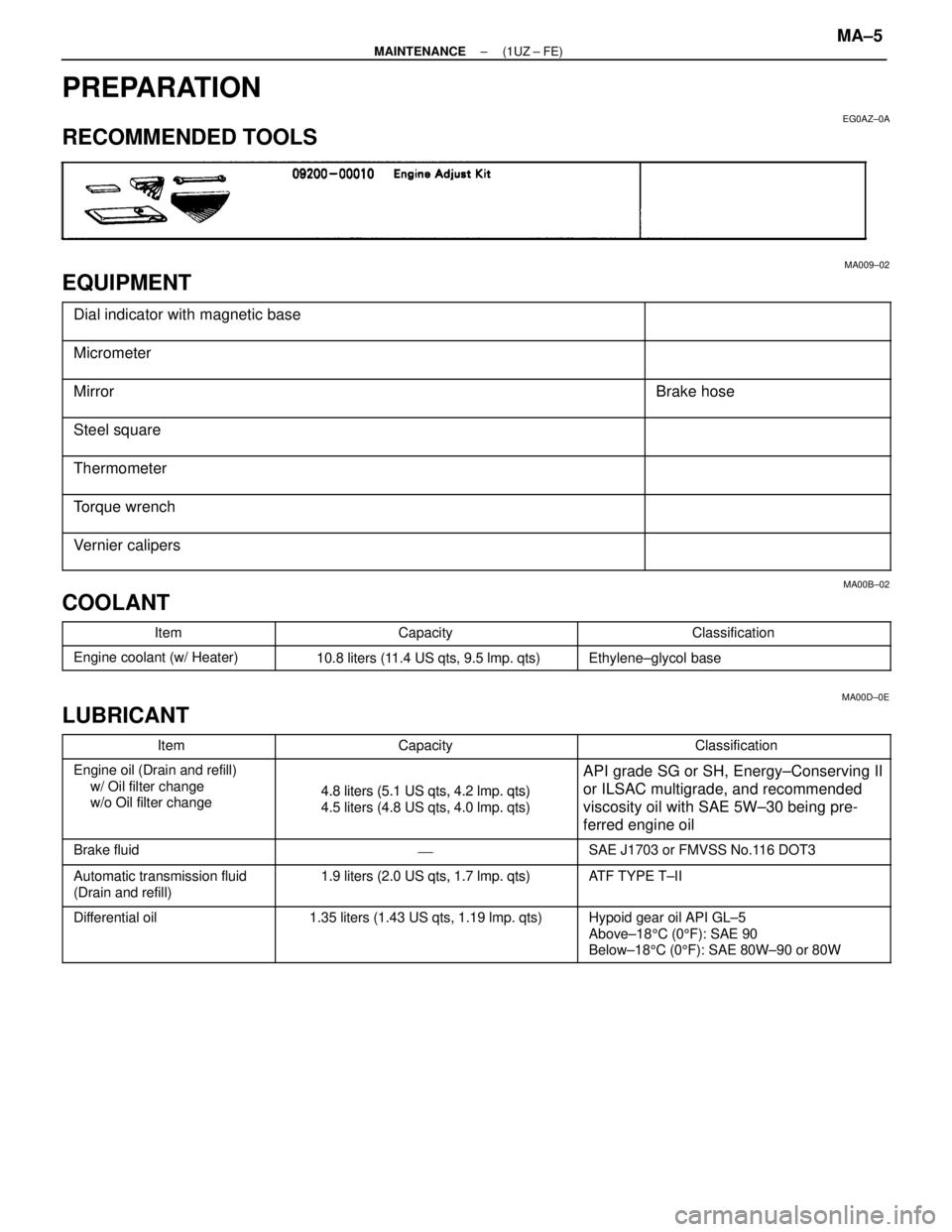
PREPARATION
EG0AZ±0A
RECOMMENDED TOOLS
MA009±02
EQUIPMENT
������������������\
������� �
������������������\
������
������������������\
�������Dial indicator with magnetic base������������ �
�����������
������������
������������������\
������� ������������������\
�������Micrometer
������������������\
������� �
������������������\
������
������������������\
�������MirrorBrake hose
������������������\
������� �
������������������\
������
������������������\
�������
Steel square
������������������\
������� ������������������\
�������Thermometer
������������������\
������� �
������������������\
������
������������������\
�������Torque wrench
������������������\
������� ������������������\
�������Vernier calipers
MA00B±02
COOLANT���������� �
���������Item
�������������� �
�������������Capacity
�������������� �
�������������Classification���������� �
���������
����������Engine coolant (w/ Heater)10.8 liters (11.4 US qts, 9.5 lmp. qts)Ethylene±glycol base
MA00D±0E
LUBRICANT
���������� ����������Item�������������� ��������������Capacity�������������� ��������������Classification���������� �
���������
����������Engine oil (Drain and refill)
w/ Oil filter change
/ Oil filt h
�������������� �
�������������
��������������4.8 liters (5.1 US qts, 4.2 lmp. qts)
�������������� �
�������������
��������������API grade SG or SH, Energy±Conserving II
or ILSAC multigrade, and recommended
���������� �
���������
����������
g
w/o Oil filter change�������������� �
�������������
��������������
4.8 liters (5.1 US qts, 4.2 lm. qts)
4.5 liters (4.8 US qts, 4.0 lmp. qts)�������������� �
�������������
��������������
or ILSAC multigrade, and recommended
viscosity oil with SAE 5W±30 being pre-
ferred engine oil
���������� ����������Brake fluid�������������� ���������������������������� ��������������SAE J1703 or FMVSS No.116 DOT3
���������� ����������Automatic transmission fluid�������������� ��������������1.9 liters (2.0 US qts, 1.7 lmp. qts)�������������� ��������������ATF TYPE T±II
����������
Automatic transmission fluid
(Drain and refill)��������������
1.9 liters (2.0 US qts, 1.7 lm . qts)
��������������
AT F TYPE TII
���������� �
���������
�
���������
����������
Differential oil�������������� �
�������������
�
�������������
��������������
1.35 liters (1.43 US qts, 1.19 lmp. qts)�������������� �
�������������
�
�������������
��������������
Hypoid gear oil API GL±5
Above±18
5C (0 5F): SAE 90
Below±18 5C (0 5F): SAE 80W±90 or 80W
±
MAINTENANCE (1UZ ± FE)MA±5
WhereEverybodyKnowsYourName
Page 2160 of 4087

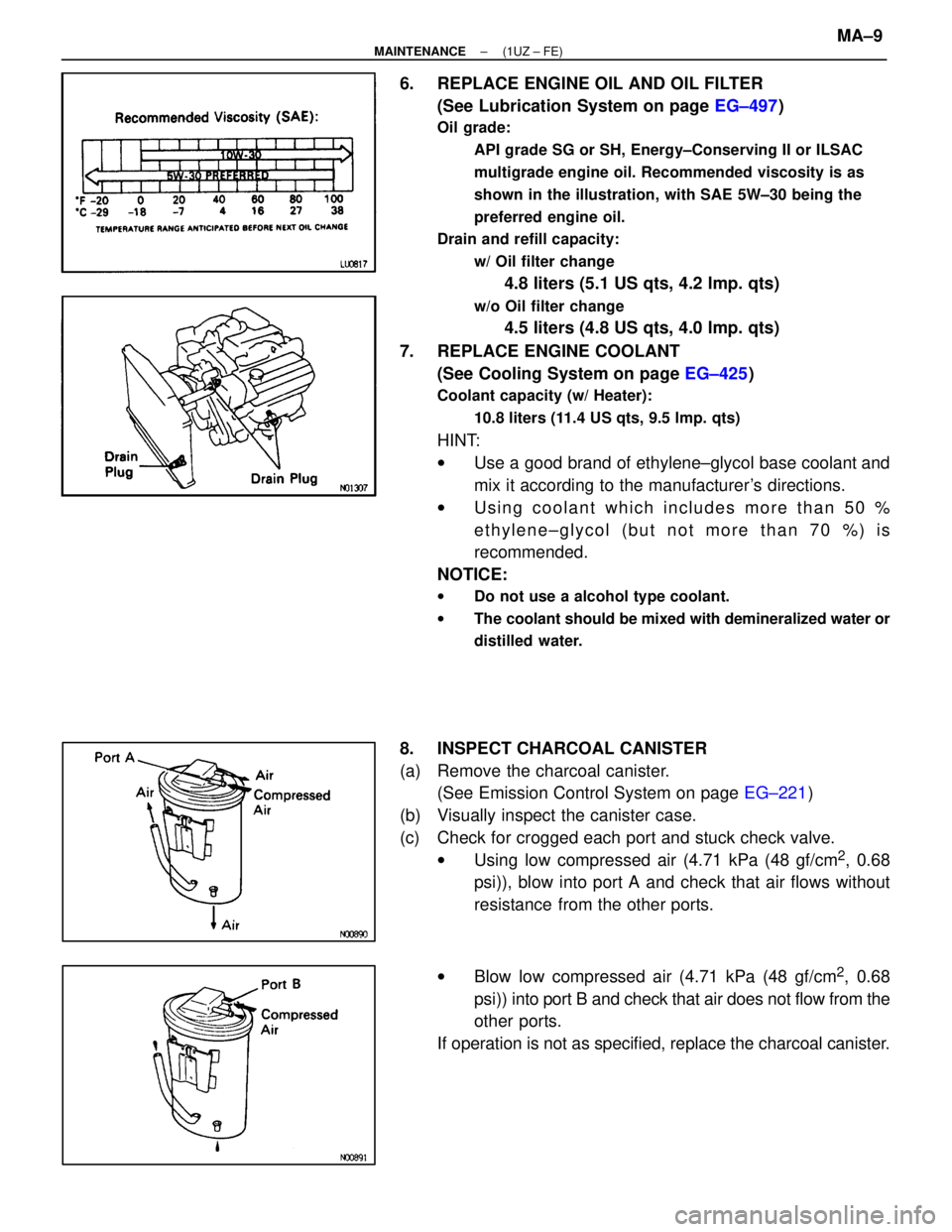
6. REPLACE ENGINE OIL AND OIL FILTER(See Lubrication System on page EG±497)
Oil grade:
API grade SG or SH, Energy±Conserving II or ILSAC
multigrade engine oil. Recommended viscosity is as
shown in the illustration, with SAE 5W±30 being the
preferred engine oil.
Drain and refill capacity:
w/ Oil filter change
4.8 liters (5.1 US qts, 4.2 lmp. qts)
w/o Oil filter change
4.5 liters (4.8 US qts, 4.0 lmp. qts)
7. REPLACE ENGINE COOLANT (See Cooling System on page EG±425)
Coolant capacity (w/ Heater):
10.8 liters (11.4 US qts, 9.5 lmp. qts)
HINT:
wUse a good brand of ethylene±glycol base coolant and
mix it according to the manufacturer's directions.
w Using coolant which includes more than 50 %
ethylene±glycol (but not more than 70 %) is
recommended.
NOTICE:
w Do not use a alcohol type coolant.
w The coolant should be mixed with demineralized water or
distilled water.
8. INSPECT CHARCOAL CANISTER
(a) Remove the charcoal canister.
(See Emission Control System on page EG±221)
(b) Visually inspect the canister case.
(c) Check for crogged each port and stuck check valve. wUsing low compressed air (4.71 kPa (48 gf/cm
2, 0.68
psi)), blow into port A and check that air flows without
resistance from the other ports.
w Blow low compressed air (4.71 kPa (48 gf/cm
2, 0.68
psi)) into port B and check that air does not flow from the
other ports.
If operation is not as specified, replace the charcoal canister.
±
MAINTENANCE (1UZ ± FE)MA±9
WhereEverybodyKnowsYourName