Page 116 of 4087
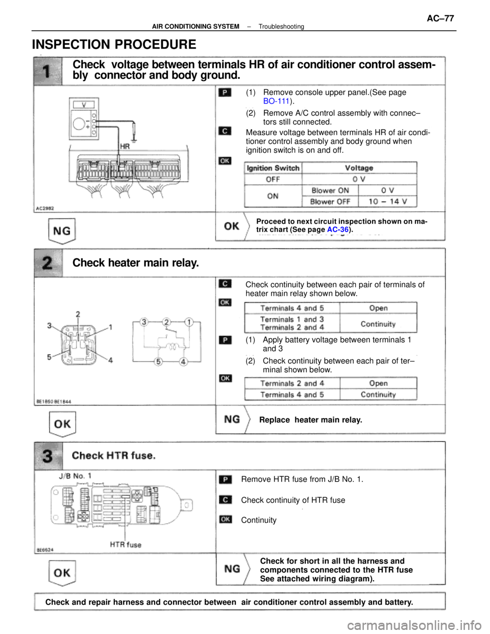
Check voltage between terminals HR of air conditioner control assem-
bly connector and body ground.
(1) Remove console upper panel.(See page BO-111 ).
(2) Remove A/C control assembly with connec±
tors still connected.
Proceed to next circuit inspection shown on ma-
trix chart (See page AC-36).
Check heater main relay.
Check continuity between each pair of terminals of
heater main relay shown below.
Measure voltage between terminals HR of air condi-
tioner control assembly and body ground when
ignition switch is on and off.
(1) Apply battery voltage between terminals 1
and 3
(2) Check continuity between each pair of ter±minal shown below.
Replace heater main relay.
Remove HTR fuse from J/B No. 1.
Check continuity of HTR fuse
Continuity
Check for short in all the harness and
components connected to the HTR fuse
See attached wiring diagram).
Check and repair harness and connector between air conditioner control \
assembly and battery.
INSPECTION PROCEDURE
±
AIR CONDITIONING SYSTEM TroubleshootingAC±77
WhereEverybodyKnowsYourName
Page 144 of 4087
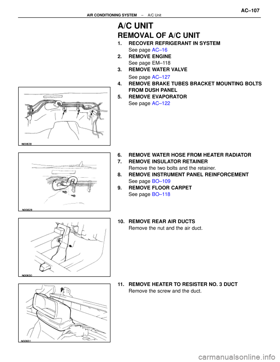
A/C UNIT
REMOVAL OF A/C UNIT
1. RECOVER REFRIGERANT IN SYSTEMSee page AC±16
2. REMOVE ENGINE See page EM±118
3. REMOVE WATER VALVE
See page AC±127
4. REMOVE BRAKE TUBES BRACKET MOUNTING BOLTS FROM DUSH PANEL
5. REMOVE EVAPORATOR See page AC±122
6. REMOVE WATER HOSE FROM HEATER RADIATOR
7. REMOVE INSULATOR RETAINER Remove the two bolts and the retainer.
8. REMOVE INSTRUMENT PANEL REINFORCEMENT See page BO±109
9. REMOVE FLOOR CARPET See page BO±118
10. REMOVE REAR AIR DUCTS Remove the nut and the air duct.
11. REMOVE HEATER TO RESISTER NO. 3 DUCT Remove the screw and the duct.
±
AIR CONDITIONING SYSTEM A/C UnitAC±107
WhereEverybodyKnowsYourName
Page 145 of 4087
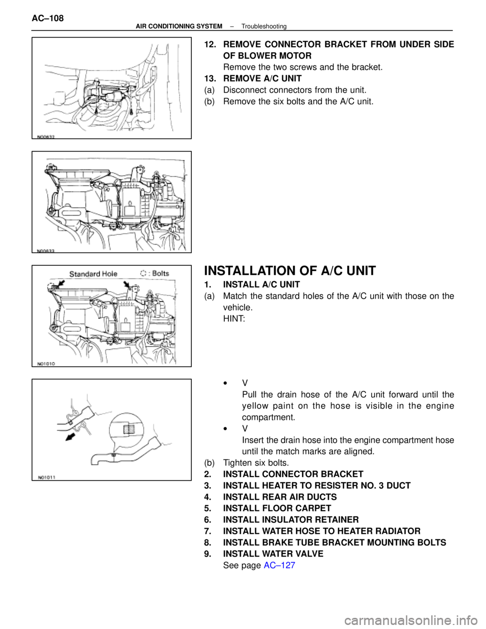
12. REMOVE CONNECTOR BRACKET FROM UNDER SIDEOF BLOWER MOTOR
Remove the two screws and the bracket.
13. REMOVE A/C UNIT
(a) Disconnect connectors from the unit.
(b) Remove the six bolts and the A/C unit.
INSTALLATION OF A/C UNIT
1. INSTALL A/C UNIT
(a) Match the standard holes of the A/C unit with those on the vehicle.
HINT:
wV
Pull the drain hose of the A/C unit forward until the
yellow paint on the hose is visible in the engine
compartment.
w V
Insert the drain hose into the engine compartment hose
until the match marks are aligned.
(b) Tighten six bolts.
2. INSTALL CONNECTOR BRACKET
3. INSTALL HEATER TO RESISTER NO. 3 DUCT
4. INSTALL REAR AIR DUCTS
5. INSTALL FLOOR CARPET
6. INSTALL INSULATOR RETAINER
7. INSTALL WATER HOSE TO HEATER RADIATOR
8. INSTALL BRAKE TUBE BRACKET MOUNTING BOLTS
9. INSTALL WATER VALVE See page AC±127
AC±108
±
AIR CONDITIONING SYSTEM Troubleshooting
WhereEverybodyKnowsYourName
Page 162 of 4087
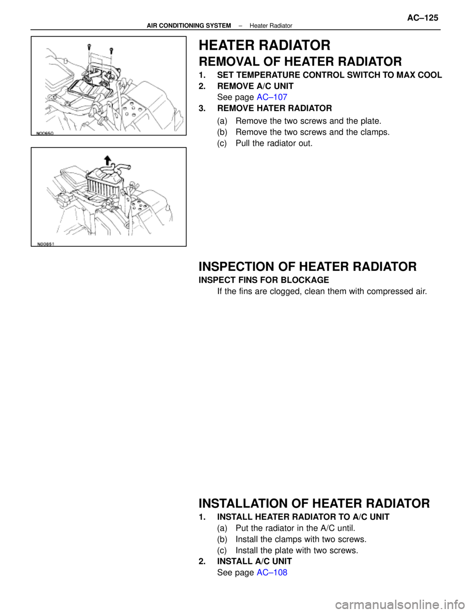
HEATER RADIATOR
REMOVAL OF HEATER RADIATOR
1. SET TEMPERATURE CONTROL SWITCH TO MAX COOL
2. REMOVE A/C UNITSee page AC±107
3. REMOVE HATER RADIATOR
(a) Remove the two screws and the plate.
(b) Remove the two screws and the clamps.
(c) Pull the radiator out.
INSPECTION OF HEATER RADIATOR
INSPECT FINS FOR BLOCKAGE If the fins are clogged, clean them with compressed air.
INSTALLATION OF HEATER RADIATOR
1. INSTALL HEATER RADIATOR TO A/C UNIT(a) Put the radiator in the A/C until.
(b) Install the clamps with two screws.
(c) Install the plate with two screws.
2. INSTALL A/C UNIT
See page AC±108
±
AIR CONDITIONING SYSTEM Heater RadiatorAC±125
WhereEverybodyKnowsYourName
Page 165 of 4087
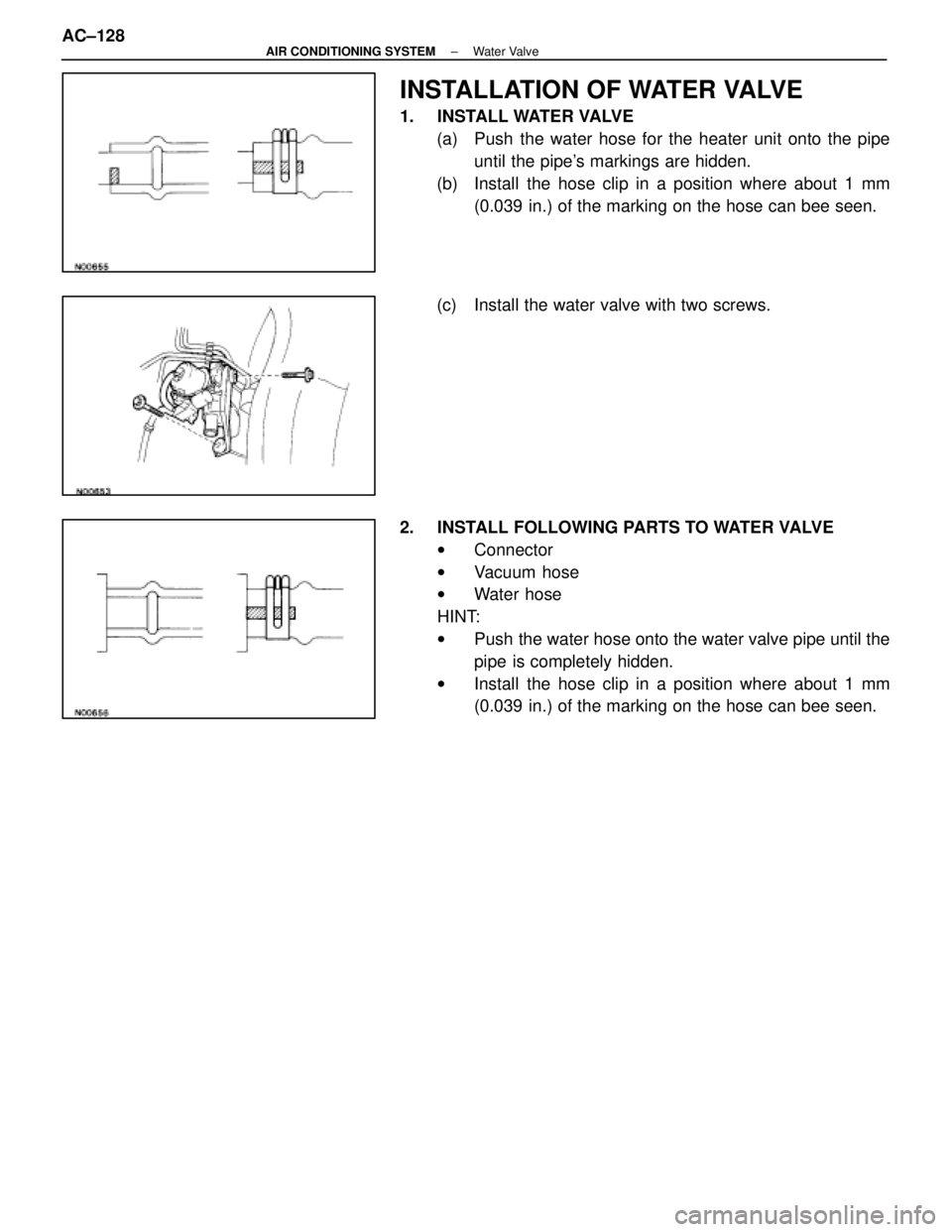
INSTALLATION OF WATER VALVE
1. INSTALL WATER VALVE(a) Push the water hose for the heater unit onto the pipe until the pipe's markings are hidden.
(b) Install the hose clip in a position where about 1 mm (0.039 in.) of the marking on the hose can bee seen.
(c) Install the water valve with two screws.
2. INSTALL FOLLOWING PARTS TO WATER VALVE wConnector
w Vacuum hose
w Water hose
HINT:
w Push the water hose onto the water valve pipe until the
pipe is completely hidden.
w Install the hose clip in a position where about 1 mm
(0.039 in.) of the marking on the hose can bee seen.
AC±128
±
AIR CONDITIONING SYSTEM Water Valve
WhereEverybodyKnowsYourName
Page 255 of 4087

(1) Turn ignition switch LOCK.
(2) Disconnect center airbag sensor assemblyconnector.
(3) Turn ignition switch ON. But do not start engine.
(4) Measure voltage at IG
2 or ACC on connector
wire harness side of center airbag assembly and
operate electric system (defogger, wiper,
headlight, heater, blower, etc.).
Voltage: 6 V ± 11.5 V at IG
2 and ACC.
(5) Turn electric system switch OFF.
(6) Turn ignition switch LOCK.
(7) Remove voltmeter and connect center airbag sensor assembly.
Does airbag warning light turn off after approx. 10 seconds?
Preparation.
Turn ignition switch ON.
Operate electric system checked in [ 1 ] (4) and
check that airbag warning light goes off after
approx. 10 seconds.
Check diagnostic code, and if a malfunction
code is output, perform troubleshooting
according to malfunction code. If a normal
code is output, replace center airbag
sensor assembly.
Check battery and charging system
(See page CH±1)
INSPECTION PROCEDURE
AB±41SRS AIRBAG ± Troubleshooting
WhereEverybodyKnowsYourName
Page 468 of 4087
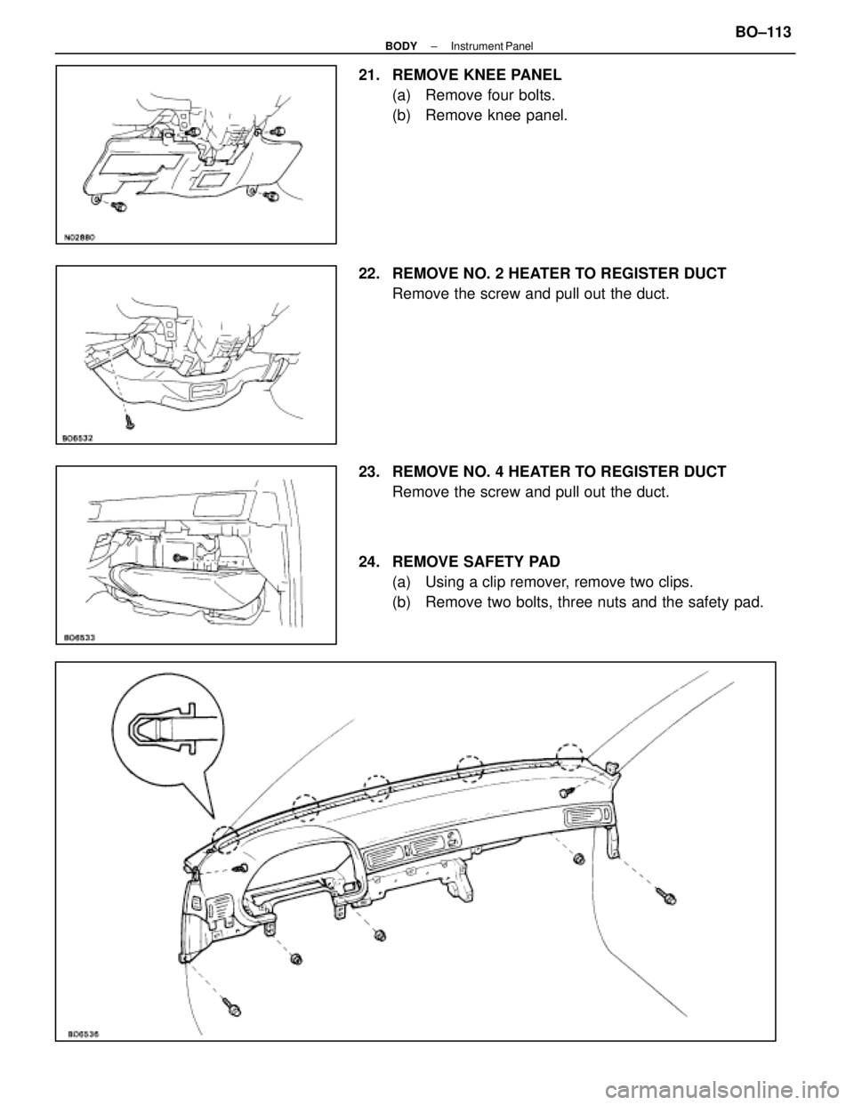
21. REMOVE KNEE PANEL(a) Remove four bolts.
(b) Remove knee panel.
22. REMOVE NO. 2 HEATER TO REGISTER DUCT Remove the screw and pull out the duct.
23. REMOVE NO. 4 HEATER TO REGISTER DUCT Remove the screw and pull out the duct.
24. REMOVE SAFETY PAD (a) Using a clip remover, remove two clips.
(b) Remove two bolts, three nuts and the safety pad.
±
BODY Instrument PanelBO±113
WhereEverybodyKnowsYourName
Page 469 of 4087
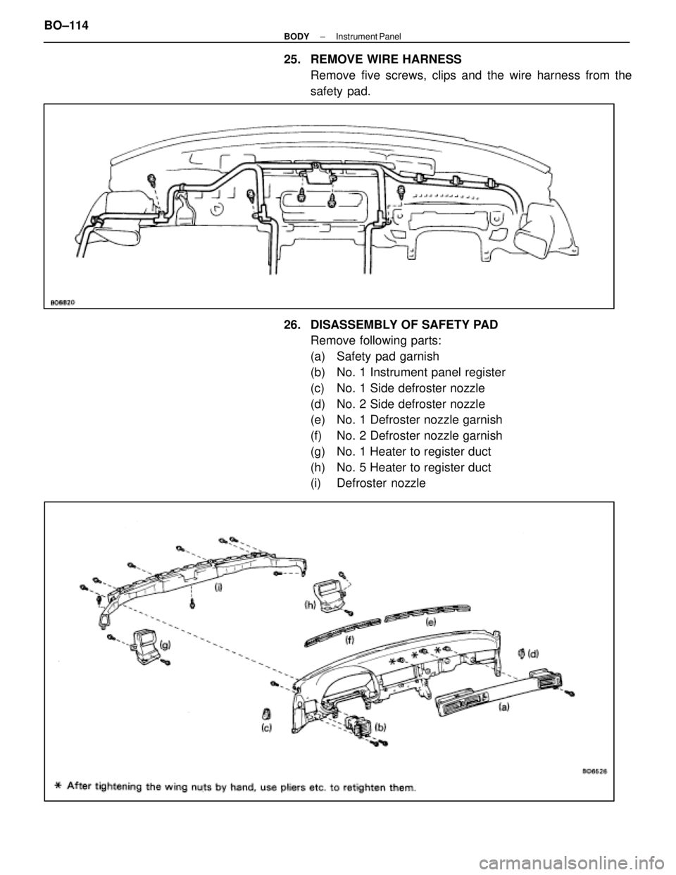
25. REMOVE WIRE HARNESSRemove five screws, clips and the wire harness from the
safety pad.
26. DISASSEMBLY OF SAFETY PADRemove following parts:
(a) Safety pad garnish
(b) No. 1 Instrument panel register
(c) No. 1 Side defroster nozzle
(d) No. 2 Side defroster nozzle
(e) No. 1 Defroster nozzle garnish
(f) No. 2 Defroster nozzle garnish
(g) No. 1 Heater to register duct
(h) No. 5 Heater to register duct
(i) Defroster nozzle
BO±114±
BODY Instrument Panel
WhereEverybodyKnowsYourName