Page 561 of 4087
INSPECTION OF MIRROR DEFOGGER
INSPECT MIRROR DEFOGGER(a) Connect the positive (+) lead from the battery to terminal
7 and the negative (±) lead to terminal 8.
(b) Check that the mirror becomes warm.
HINT: It will take a short time for the mirror to become warm.
If the mirror does not become warm, replace the mirror as-
sembly.
Troubleshooting
You will find the cause of trouble more easily using the table shown below. In this table, the number indicate
the order priority of the causes in trouble. Check each part in the order s\
hown. If necessary, replace the parts.
See pageBE±4 ,20BE±4,20BE±4,22BE±172BE±173 ±±BE±173 ±±BE±174
TroubleParts
name
HEATER FuseMIR±HTR FuseDEFOG FuseDefogger SwitchDefogger RelayWire HarnessDefogger WiresCKE CoilMirror Defogger
All defogger systems do not operate.11234
Rear window defogger does not operate.312
Mirror Defogger does not operate.132
±
BODY ELECTRICAL SYSTEM Defogger SystemBE±175
WhereEverybodyKnowsYourName
Page 744 of 4087
OKNG
NGOK
OKNG
INSPECTION PROCEDURE
1Check DOME fuse.
C
OK
PRemove DOME fuse from R/B No. 2.
Check continuity of DOME fuse.
Continuity
Check for short in all the harness and components con-
nected to the DOME fuse (See attached wiring diagram).
2Check voltage between terminals +B1 and E of ECU connector.
C
OK
P1. Remove the No. 1 under cover and heater duct.
2. Disconnect the theft deterrent and door lock ECUconnectors.
Measure voltage between terminals +B1 and E of ECU
connector.
Voltage: 10 ± 14 V
Proceed to next circuit inspection shown on matrix chart
(See page BE±371).
3Check for open in harness and connector between ECU and body ground (Se\
e page IN±27).
Repair or replace harness or connector.
Check and repair harness and connector between
ECU and battery.
±
BODY ELECTRICAL SYSTEM Door Lock Control SystemBE±377
WhereEverybodyKnowsYourName
Page 746 of 4087

OKNG
NGOK
*1: The power source is supplied to the actuator (doorlock motor, luggage compartment door opener mo-
tor) through the theft deterrent and door lock ECU.
Accordingly, if a short circuit of the W/H or actuator
occurs in the actuator circuit, the DOOR fusible link
may become OPEN, so also inspect the actuator
(door lock motor circuit on page BE±380, and the
luggage compartment door opener motor circuit on
page BE±382 ).
INSPECTION PROCEDURE
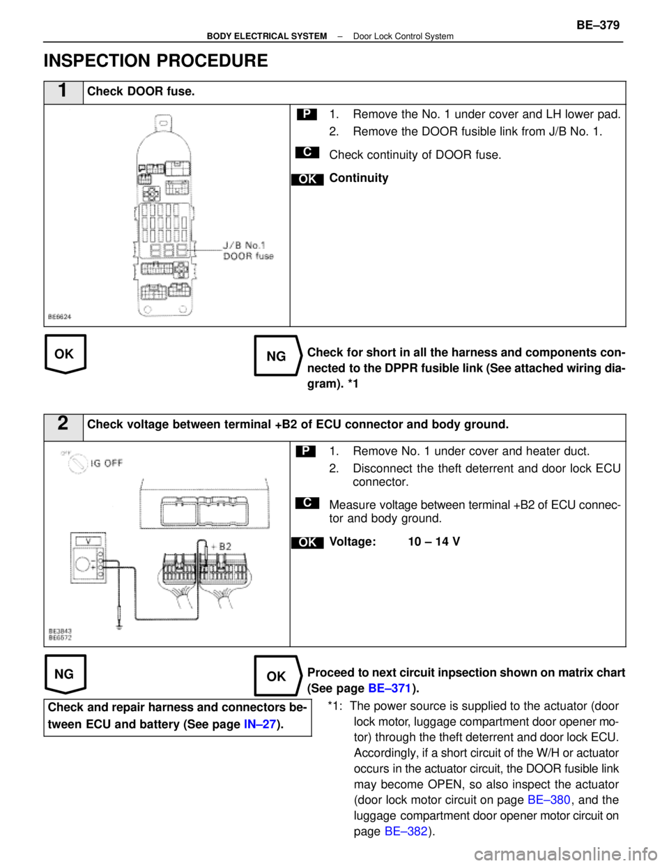
1Check DOOR fuse.
C
OK
P1. Remove the No. 1 under cover and LH lower pad.
2. Remove the DOOR fusible link from J/B No. 1.
Check continuity of DOOR fuse.
Continuity
Check for short in all the harness and components con-
nected to the DPPR fusible link (See attached wiring dia-
gram). *1
2Check voltage between terminal +B2 of ECU connector and body ground.
C
OK
P1. Remove No. 1 under cover and heater duct.
2. Disconnect the theft deterrent and door lock ECU connector.
Measure voltage between terminal +B2 of ECU connec-
tor and body ground.
Voltage: 10 ± 14 V
Proceed to next circuit inpsection shown on matrix chart
(See page BE±371).
Check and repair harness and connectors be-
tween ECU and battery (See page IN±27).
±
BODY ELECTRICAL SYSTEM Door Lock Control SystemBE±379
WhereEverybodyKnowsYourName
Page 804 of 4087
PREPARATION
SST (SPECIAL SERVICE TOOLS)
IllustrationPart No.Part NameNote
09213±31021
Crankshaft Pulley
Puller
For removing steering wheel
RECOMMENDED TOOLS
IllustrationPart No.Part NameNote
09082±00015TOYOTA
Electrical Tester
09041±0030Torx Driver
T30
For removing and installing steering wheel pad and
power window motor
09042±00010Torx Socket
T30For removing and installing steering wheel pad and
power window motor
EQUIPMENT
Part NameNote
Voltmeter
Ammeter
Ohmmeter
Test lead
ThermometerWater temperature sender gauge, Engine oil level, Warning switch, Seat heater
SyphonBrake fluid level warning switch
Oil bathEngine oil level warning switch
Bulb (1.4 W)Coolant level warning ECU
Bulb (3.4 W)Fuel sender, gauge, Seat belt warning relay
Bulb (21 W)Turn signal flasher relay
Dry cell batteryFuel sender gauge
Heat lightSeat heater
Hexagon wrench (6 mm)Power seat
BE±8±
BODY ELECTRICAL SYSTEM Preparation
WhereEverybodyKnowsYourName
Page 814 of 4087

Description
The power source supplies power to each of the vehicle's electrical devices. It is composed of the battery, fuses
and relays, which are located centrally at relay block No. 2 and relay block No. 6 i\
n the engine compartment
and junction block No. 1 relay block No. 4 and relay block No. 5 in the \
cabin near the driver's feet.
Related systems for each Fuse
No.Part NameRelated Systems or Parts
1IGN � Charging System � AIR±BAG System1IGN � Engine
2ST � Starter
3WIPER � Wiper and Washer System
4HTR � Defogger System � A/C System
5ENGINE � Charging System
6RADIO NO. 2 � Audio System � Power Mirror System
� Cigarette Lighter � A/C System
7CIG � Combination Meter System � AIR±BAG System7CIG � Shift Lock System � Theft Deterrent System
� TEL System
8STOP � Stop Light System � Cruise Control System
9TURN � Turn Signal and Hazard
Warning Light System � Cornnering Light System
10MIR HTR � Mirror Heater System
11PANEL � Illumination Light System
12ECU±B � Combination Meter System � AIR±BAG System
� Combination Meter System � ECT System
13GAUGE � Back±Up Light � Transmission Indicator
� Light Failare Sensor � ABS and TRAC
� Power Seat System � Door Lock Control System
� TEL System � Shift Lock System
14ECU±IG � Radiator Fan � Auto Antenna
� Electric Tension Reducer System � Power Steering
� Auto±Tilt away Steering � Cruise Control System
15TAIL � Taillight System � Side Marker15TAIL � Clearance Light
16DOOR � Power Seat System � Luggage Door Opener16DOOR � Door Lock Control System � Fuel Lid Opener System
17IG SWUpstream of ECU±IG, ENGINE, WIP, HTR, TURN, GAUGE, and ST Fuse
18PWR � Power Window System � Sliding Roof System
19ABS NO. 1 � ABS and TRAC
20AM1Upstream of MIR HTR, TAIL, PANEL, STOP, ECUA±B, DOOR and PWR Fuse
21ALTUpstream of DEF, HTR, AM1, and ABS No. 1 Fuse
BE±18±
BODY ELECTRICAL SYSTEM Power Source
WhereEverybodyKnowsYourName
Page 1140 of 4087
8. INSPECT CHARGING CIRCUIT WITH LOAD(a) With the engine running at 2,000 rpm, turn on the highbeam headlights and place the heater blower switch at
ºHIº.
(b) Check the reading on the ammeter.
Standard amperage: 30 A or more
If the ammeter reading is less than standard amperage, re-
pair the alternator. (See page CH±9)
HINT: With the battery fully charged, the indication will some-
times be less than standard amperage.
9. REINSTALL ENGINE UNDER COVER
CH±8
±
CHARGING SYSTEM On±Vehicle Inspection
WhereEverybodyKnowsYourName
Page 1264 of 4087

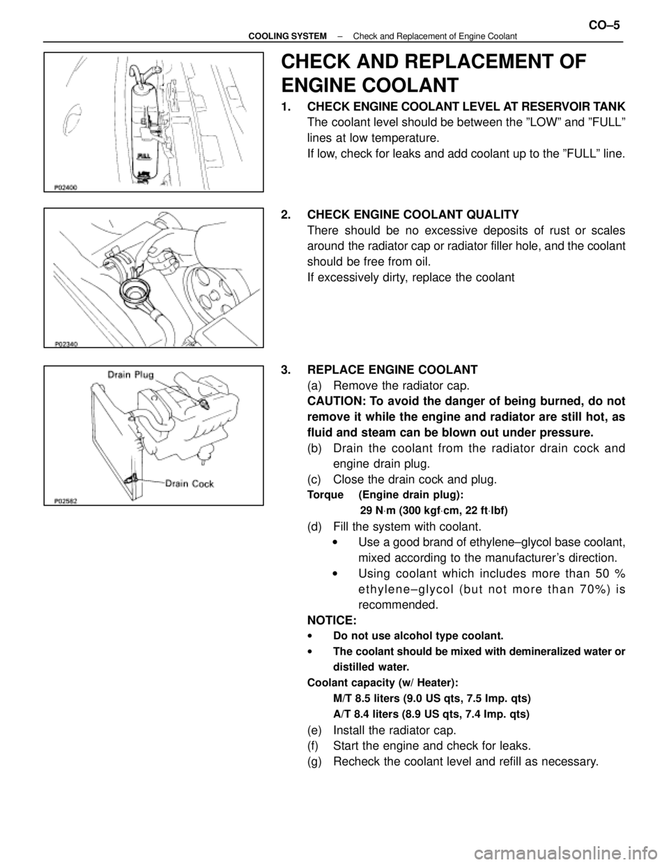
CHECK AND REPLACEMENT OF
ENGINE COOLANT
1. CHECK ENGINE COOLANT LEVEL AT RESERVOIR TANK
The coolant level should be between the ºLOWº and ºFULLº
lines at low temperature.
If low, check for leaks and add coolant up to the ºFULLº line.
2. CHECK ENGINE COOLANT QUALITY There should be no excessive deposits of rust or scales
around the radiator cap or radiator filler hole, and the coolant
should be free from oil.
If excessively dirty, replace the coolant
3. REPLACE ENGINE COOLANT (a) Remove the radiator cap.
CAUTION: To avoid the danger of being burned, do not
remove it while the engine and radiator are still hot, as
fluid and steam can be blown out under pressure.
(b) Drain the coolant from the radiator drain cock andengine drain plug.
(c) Close the drain cock and plug.
Torque (Engine drain plug):
29 NVm (300 kgf Vcm, 22 ft Vlbf)
(d) Fill the system with coolant.
w Use a good brand of ethylene±glycol base coolant,
mixed according to the manufacturer's direction.
w Using coolant which includes more than 50 %
ethylene±glycol (but not more than 70%) is
recommended.
NOTICE:
w Do not use alcohol type coolant.
w The coolant should be mixed with demineralized water or
distilled water.
Coolant capacity (w/ Heater): M/T 8.5 liters (9.0 US qts, 7.5 Imp. qts)
A/T 8.4 liters (8.9 US qts, 7.4 Imp. qts)
(e) Install the radiator cap.
(f) Start the engine and check for leaks.
(g) Recheck the coolant level and refill as necessary.
±
COOLING SYSTEM Check and Replacement of Engine CoolantCO±5
WhereEverybodyKnowsYourName
Page 1266 of 4087
(f) Slowly add coolant to water inlet housing until it is full.w Use a good brand of ethylene±glycol base coolant,
mixed according to the manufacturer's directions.
w Using coolant which includes more than 50%
ethylene±glycol (but not more 70%) than is
recommended.
NOTICE:
w Do not use alcohol type coolant.
w The coolant should be mixed with demineralized water or
distilled water.
Capacity (w/ Heater): 10.8 liters (11.4 US qts, 9.5 lmp. qts)
(g) Reinstall a new gasket and filler plug to the water inlethousing.
Torque: 44 N Vm (450 kgf Vcm, 33 ft Vlbf)
(h) Slowly add coolant to reservoir tank until it is full.
(i) Reinstall the radiator cap.
(j) Bleed the cooling system.
w Start the engine, and open the heater water valve.
w Maintain the engine speed at 2,000 rpm, and warm
up the engine.
(k) Check for leaks.
(l) Recheck the coolant level and refill as necessary.
±
COOLIING SYSTEM Check and Replacement of Engine CoolantCO±7
WhereEverybodyKnowsYourName