Page 1823 of 4087
(p) Remove the bolt holding the engine wire protector fromthe heater valve bracket.
(q) Remove the two nuts holding the engine wire clamp from the body.
12. (M/T) REMOVE TRANSMISSION SHIFT LEVER
(a) Using a screwdriver, pry out the rear side of the cupholder. Remove the cup holder.
(b) Remove the shift lever knob.
(c) Using a screwdriver, pry out the upper rear console panel.
(d) Remove the six mounting screws.
(e) Using a screwdriver, pry out the upper console panel.
(f) Remove the eight mounting bolts and shift lever.
EM±68
±
ENGINE MECHANICAL Cylinder Block
WhereEverybodyKnowsYourName
Page 1864 of 4087
 Install the bolt holding the engine wire protector on thebody.
(d) Install the ground strap to the bracket on the body.
(e) Connect the VSV connector.
(f) Connect the following hose: (1) Hea")
(c) Install the bolt holding the engine wire protector on thebody.
(d) Install the ground strap to the bracket on the body.
(e) Connect the VSV connector.
(f) Connect the following hose: (1) Heater water hose to water by±pass pipe
(2) Heater water hose to heater water valve
(3) Vacuum hose (from VSV for heater water valve) to
check valve.
(g) Install the generator wire with the nut and cap.
(h) Connect the following connector: (1) Ignition coil connector
(2) Noise filter connector
(i) Install the wire harness with the two wire clamps.
(j) Connect the PS pressure switch connector.
(k) Install the ground strap on the cylinder block.
(l) Connect the PS solenoid valve connector and wire
clamp.
(m) Using a 6 mm hexagon wrench, install the connector bracket with the bolt.
(n) Connect the following connectors: (1) Two connectors to engine room main wire
(2) Igniter connector
(3) Theft deterrent horn connector
(o) Install the wire harness with the two wire clamps.
±
ENGINE MECHANICAL Cylinder BlockEM±109
WhereEverybodyKnowsYourName
Page 1867 of 4087
 Install the hose clamp.
(d) Connect the following hoses:(1) PS air hose to No. 4 timing belt cover
(2) PCV hose to No. 2 cylinder head cover
(e) Connect the volume air flow meter connector.")
(c) Install the hose clamp.
(d) Connect the following hoses:(1) PS air hose to No. 4 timing belt cover
(2) PCV hose to No. 2 cylinder head cover
(e) Connect the volume air flow meter connector.
(f) Connect the high±tension cord to the ignition coil.
18. CONNECT CONTROL CABLES TO THROTTLE BODY Connect the following cables:(1) Accelerator cables
(2) (A/T)
Throttle control cable
(3) Cruise control actuator cable
19. INSTALL BATTERY
20. FILL ENGINE WITH COOLANT (See page CO±5)
Capacity (w/Heater): M/T 8.5 liters (9.0 US qts, 7.5 lmp. qts)
A/T 8.4 liters (8.9 US qts, 7.4 lmp. qts)
21. START ENGINE AND CHECK FOR LEAKS
22. (A/T)CHECK AUTOMATIC TRANSMISSION FLUID LEVEL
(See page MA±11)
NOTICE: Do not overfill.
23. CHECK IGNITION TIMING (See page IG±14)
Ignition timing:
105 BTDC @ idle
(w/ Terminals TE1 and E1 connected)
24. INSTALL ENGINE UNDER COVER
25. INSTALL HOOD
26. PERFORM ROAD TEST Check for abnormal noise, shock, slippage, correct shift
points and smooth operation.
27. RECHECK ENGINE COOLANT AND ENGINE OIL LEVELS
EM±112
±
ENGINE MECHANICAL Cylinder Block
WhereEverybodyKnowsYourName
Page 1910 of 4087
6. REMOVE UPPER HIGH±TENSION CORD COVER(a) Remove the two mounting bolts.
(b) Disconnect the front side claw groove of the cord coverfrom the claw of the lower cover, and remove the cord
cover.
7. REMOVE THROTTLE BODY (a) Disconnect the following connectors:(1) Throttle position sensor connector
(2) (w/ TRAC) Sub±throttle position sensor connector
(3) (w/ TRAC) Sub±throttle actuator connector
(b) Disconnect the following hoses: (1) Heater water hose from heater water valve
(2) Water by±pass hose from ISC valve
(3) (USA Spec.) Vacuum hose from throttle body
(4) (Exc. USA Spec.) Three vacuum hoses from throttle body FI±71
EFI SYSTEM
± Air Induction System (Throttle Body)
WhereEverybodyKnowsYourName
Page 1917 of 4087
(4) Heater water hose to heater water valve
(f) Connect the following connectors: (1) Throttle position sensor connector
(2) (w/ TRAC)
Sub±throttle position sensor connector
(3) (w/ TRAC) Sub±throttle actuator connector
2. INSTALL UPPER HIGH±TENSION CORD COVER (a) Fit portion A of the upper high±tension cover, matchingit with the top of the lower high±tension cord cover.
(b) Push the front side of the high±tension cord cover, and connect the front side claw groove of the upper
high±tension cord cover to the claw of the lower
high±tension cord cover.
(c) Install the upper high±tension cord cover with the two bolts.
3. INSTALL INTAKE AIR CONNECTOR (a) Connect the end portions of the intake air connector tothe throttle body and air cleaner hose.
(b) Tighten the two hose clamps.
(c) Install the bolt holding the intake air connector to the
cylinder head cover.
FI±78
EFI SYSTEM
± Air Induction System (Throttle Body)
WhereEverybodyKnowsYourName
Page 1928 of 4087
4. (A/T)
REMOVE CUP HOLDERUsing a screwdriver, pry out the rear side of the cup holder.
Remove the cup holder.
5. REMOVE UPPER REAR CONSOLE PANEL Using a screwdriver, pry out the console panel.
6. (A/T)
REMOVE UPPER CONSOLE PANEL (a) Remove the six mounting screws.
(b) Using a screwdriver, pry out the console panel.
7. DISCONNECT SUB±OXYGEN SENSOR CONNECTOR
8. INSPECT HEATER RESIST ANCE OF SUB±OXYGEN
SENSOR
Using an ohmmeter, measure the resistance between the ter-
minals +B and HT.
Resistance: 5.1±6.3 � at 20 5C (68 5F)
FI±78±
EFI SYSTEM
Electronic Control System (Sub±Oxygen Sensor (USA Spec. only))
WhereEverybodyKnowsYourName
Page 1971 of 4087
3. DISCONNECT CABLE FROM NEGATIVE TERMINAL OFBATTERY
CAUTION: Work must be started after approx. 20 se-
conds or longer from the time the ignition switch is
turned to the ºLOCKº position and the negative (±) termi-
nal cable is disconnected from the battery.
4. INSPECT HEATER RESIST ANCE OF MAIN OXYGEN
SENSORS
(a) Disconnect the oxygen sensor connectors.
(b) Using an ohmmeter, measure the resistance between the terminals +B and HT.
Resistance: 5.1±6.3 � at 20 °C (68 °F)
If the resistance is not as specified, replace the sensor.
Torque: 44 N Vm (450 kgf Vcm, 33 ft Vlbf)
(c) Reconnect the oxygen sensor connectors.
5. RECONNECT CABLE TO NEGATIVE TERMINAL OF BATTERY
FI±116
EFI SYSTEM
± Electronic Control System (Main Oxygen Sensors)
WhereEverybodyKnowsYourName
Page 1975 of 4087
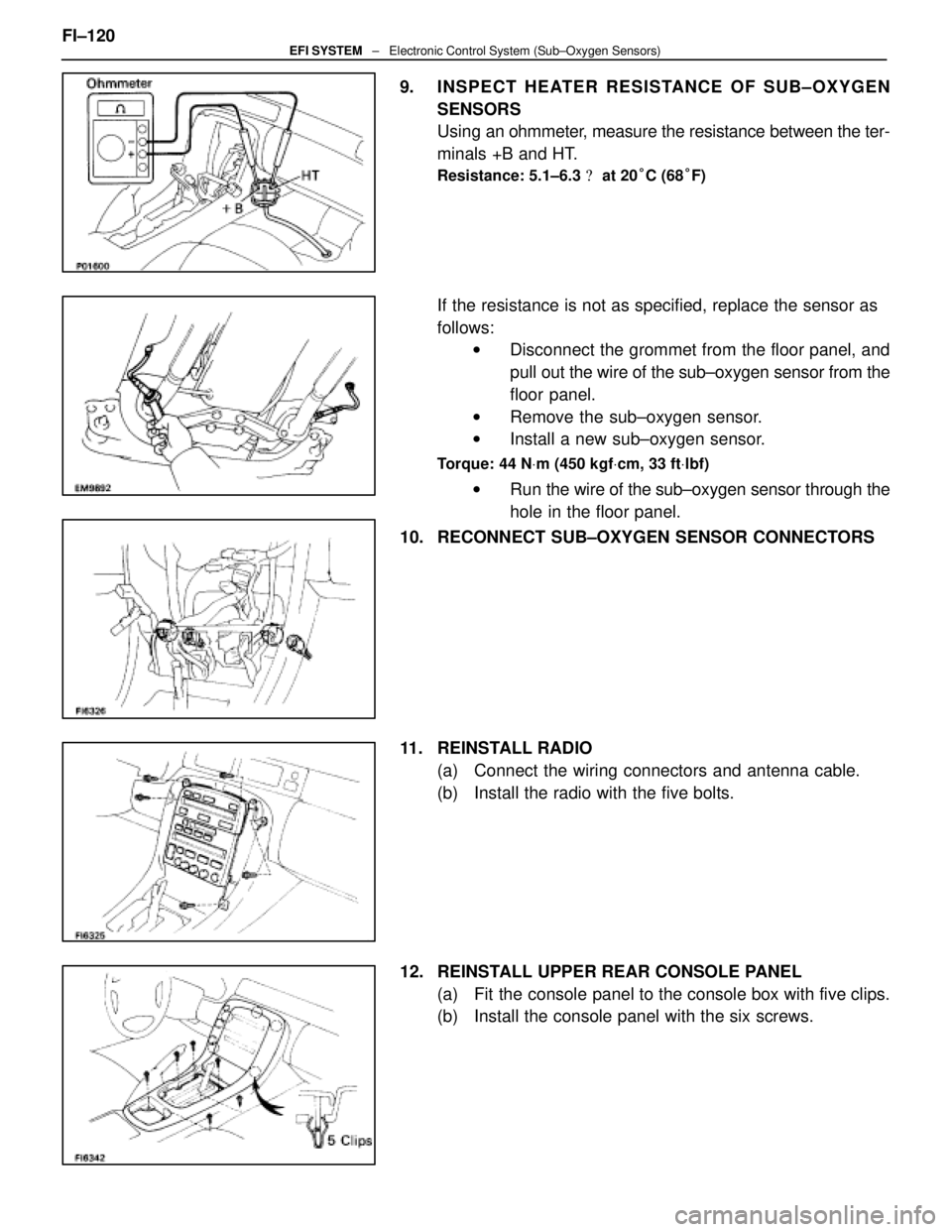
9. INSPECT HEATER RESISTANCE OF SUB±OXYGEN
SENSORS
Using an ohmmeter, measure the resistance between the ter-
minals +B and HT.
Resistance: 5.1±6.3 � at 20 °C (68 °F)
If the resistance is not as specified, replace the sensor as
follows:
w Disconnect the grommet from the floor panel, and
pull out the wire of the sub±oxygen sensor from the
floor panel.
w Remove the sub±oxygen sensor.
w Install a new sub±oxygen sensor.
Torque: 44 N Vm (450 kgf Vcm, 33 ft Vlbf)
w Run the wire of the sub±oxygen sensor through the
hole in the floor panel.
10. RECONNECT SUB±OXYGEN SENSOR CONNECTORS
11. REINSTALL RADIO (a) Connect the wiring connectors and antenna cable.
(b) Install the radio with the five bolts.
12. REINSTALL UPPER REAR CONSOLE PANEL (a) Fit the console panel to the console box with five clips.
(b) Install the console panel with the six screws.
FI±120
EFI SYSTEM
± Electronic Control System (Sub±Oxygen Sensors)
WhereEverybodyKnowsYourName
 Remove the bolt holding the engine wire protector fromthe heater valve bracket.
(q) Remove the two nuts holding the engine wire clamp from the body.
12. (M/T) REMOVE TRANSMISSION SHIFT LEVER
(a")
 Remove the two mounting bolts.
(b) Disconnect the front side claw groove of the cord coverfrom the claw of the lower cover, and remove the cord
cover.")
 Heater water hose to heater water valve
(f) Connect the following connectors: (1) Throttle position sensor connector
(2) (w/ TRAC)
Sub±throttle position sensor connector
(3) (w/ TRAC) Sub±thr")

REMOVE CUP HOLDERUsing a screwdriver, pry out the rear side of the cup holder.
Remove the cup holder.
5. REMOVE UPPER REAR CONSOLE PANEL Using a screwdriver, pry out the console panel.
6. (")