Page 2451 of 4087
6. REMOVE UPPER HIGH±TENSION CORD COVER(a) Remove the two mounting bolts.
(b) Disconnect the front side claw groove of the cord coverfrom the claw of the lower cover, and remove the cord
cover.
7. REMOVE THROTTLE BODY (a) Disconnect the following connectors:(1) Throttle position sensor connector
(2) (w/ TRAC) Sub±throttle position sensor connector
(3) (w/ TRAC) Sub±throttle actuator connector
(b) Disconnect the following hoses: (1) Heater water hose from heater water valve
(2) Water by±pass hose from ISC valve
(3) (USA Spec.) Vacuum hose from throttle body
(4) (Exc. USA Spec.) Three vacuum hoses from throttle body FI±71
EFI SYSTEM
± Air Induction System (Throttle Body)
WhereEverybodyKnowsYourName
Page 2458 of 4087
(4) Heater water hose to heater water valve
(f) Connect the following connectors: (1) Throttle position sensor connector
(2) (w/ TRAC)
Sub±throttle position sensor connector
(3) (w/ TRAC) Sub±throttle actuator connector
2. INSTALL UPPER HIGH±TENSION CORD COVER (a) Fit portion A of the upper high±tension cover, matchingit with the top of the lower high±tension cord cover.
(b) Push the front side of the high±tension cord cover, and connect the front side claw groove of the upper
high±tension cord cover to the claw of the lower
high±tension cord cover.
(c) Install the upper high±tension cord cover with the two bolts.
3. INSTALL INTAKE AIR CONNECTOR (a) Connect the end portions of the intake air connector tothe throttle body and air cleaner hose.
(b) Tighten the two hose clamps.
(c) Install the bolt holding the intake air connector to the
cylinder head cover.
FI±78
EFI SYSTEM
± Air Induction System (Throttle Body)
WhereEverybodyKnowsYourName
Page 2496 of 4087
3. DISCONNECT CABLE FROM NEGATIVE TERMINAL OFBATTERY
CAUTION: Work must be started after approx. 20 se-
conds or longer from the time the ignition switch is
turned to the ºLOCKº position and the negative (±) termi-
nal cable is disconnected from the battery.
4. INSPECT HEATER RESIST ANCE OF MAIN OXYGEN
SENSORS
(a) Disconnect the oxygen sensor connectors.
(b) Using an ohmmeter, measure the resistance between the terminals +B and HT.
Resistance: 5.1±6.3 � at 20 °C (68 °F)
If the resistance is not as specified, replace the sensor.
Torque: 44 N Vm (450 kgf Vcm, 33 ft Vlbf)
(c) Reconnect the oxygen sensor connectors.
5. RECONNECT CABLE TO NEGATIVE TERMINAL OF BATTERY
FI±116
EFI SYSTEM
± Electronic Control System (Main Oxygen Sensors)
WhereEverybodyKnowsYourName
Page 2500 of 4087
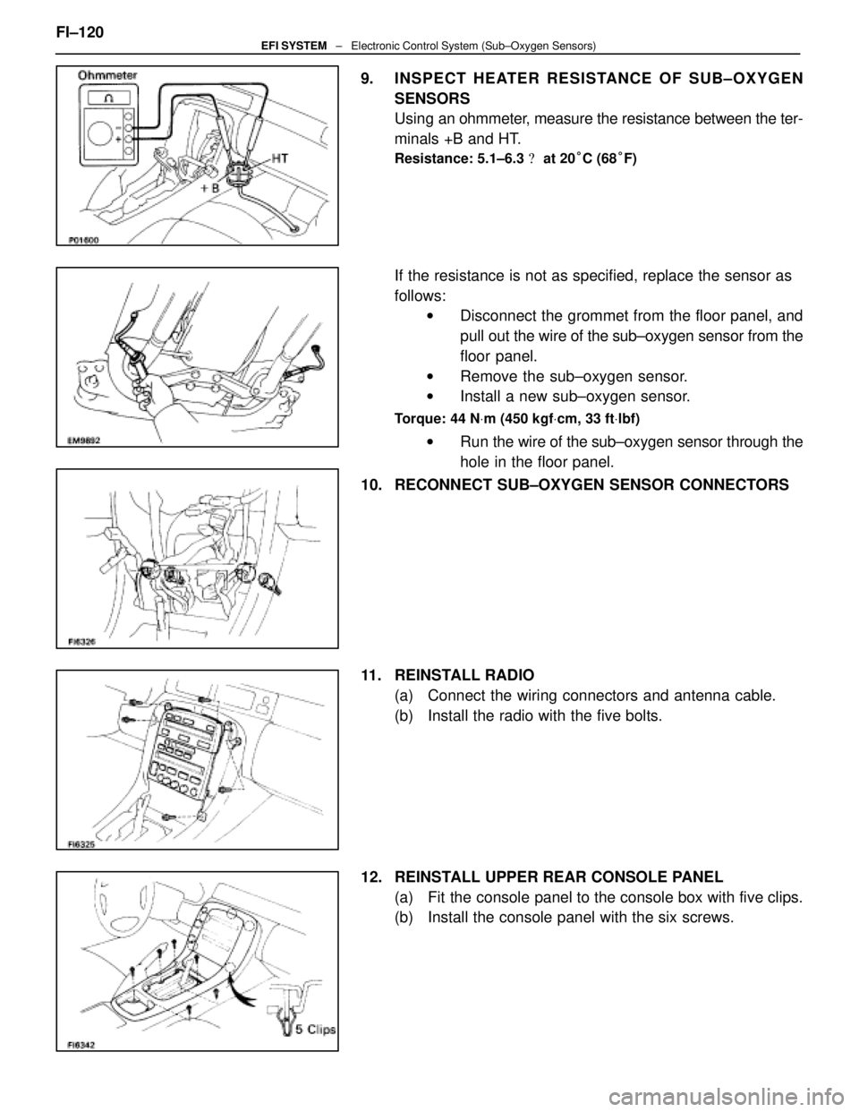
9. INSPECT HEATER RESISTANCE OF SUB±OXYGEN
SENSORS
Using an ohmmeter, measure the resistance between the ter-
minals +B and HT.
Resistance: 5.1±6.3 � at 20 °C (68 °F)
If the resistance is not as specified, replace the sensor as
follows:
w Disconnect the grommet from the floor panel, and
pull out the wire of the sub±oxygen sensor from the
floor panel.
w Remove the sub±oxygen sensor.
w Install a new sub±oxygen sensor.
Torque: 44 N Vm (450 kgf Vcm, 33 ft Vlbf)
w Run the wire of the sub±oxygen sensor through the
hole in the floor panel.
10. RECONNECT SUB±OXYGEN SENSOR CONNECTORS
11. REINSTALL RADIO (a) Connect the wiring connectors and antenna cable.
(b) Install the radio with the five bolts.
12. REINSTALL UPPER REAR CONSOLE PANEL (a) Fit the console panel to the console box with five clips.
(b) Install the console panel with the six screws.
FI±120
EFI SYSTEM
± Electronic Control System (Sub±Oxygen Sensors)
WhereEverybodyKnowsYourName
Page 2507 of 4087

TerminalNo.SymbolConnectionTerminalNo.SymbolConnection
E10± 21NCOT/M Input Speed SensorE10 ± 51±
22±52HTL2LH Sub±Oxygen Sensor Heater
23SP2No.2 Speed Senso")
TERMINALS OF ENGINE & ECT ECU (Cont'd)
TerminalNo.SymbolConnectionTerminalNo.SymbolConnection
E10± 21NCOT/M Input Speed SensorE10 ± 51±
22±52HTL2LH Sub±Oxygen Sensor Heater
23SP2No.2 Speed Sensor for ECT53HTR2RH Sub±Oxygen Sensor Heater
24±54±
25G2LH (No.2) Cam Position Sensor55±
26G1RH (No.1) Cam Position Sensor56IGT2No.2 Igniter for RH Bank
27NEEngine Speed Sensor57IGT1No.1 Igniter for LH Bank
28VF2Check Connector58IGF1No.1 Igniter for LH Bank
29VF1Check Connector59IGF2No.2 Igniter for RH Bank
30±60±
31±61±
32ISC4ISC Valve62±
33ISC3ISC Valve63IDL2Sub±Throttle Position Sensor
34ISC2ISC Valve64IDL1Throttle Position Sensor
35ISC1ISC Valve65E2Sensor Ground
36*� EGR4EGR Valve66KSAir Flow Meter
37*� EGR3EGR Valve67OXR2
38*� EGR2EGR Valve68OXL2LH Sub±Oxygen Sensor
39*� EGR1EGR Valve69E1ECU Ground39*� EGRVSV for EGR69E1ECU Ground
40±70±
41VCThrottle Position Sensor
Air Flow Meter71HTL1LH Main Oxygen Sensor
42VTA2Fuel Pump ECU72HTR1RH Main Oxygen Sensor
43VTA1A/C Magnet Clutch Relay73FPUVSV for Fuel Pressure Control
Value
44THWWater Temp. Sensor74*� PA GVSV for EVAP
45THAIntake Air Temp. Sensor75±
46THGEGR Gas Temp. Sensor76NSWNeutral Start Switch
47OXR1RH Main Oxygen Sensor77STAStarter Relay
48OXL1LH Main Oxygen Sensor78STJCold Start Injector
49KNK2RH (No.2) Knock Sensor79E02Power Ground
50KNK1LH (No.1) Knock Sensor80E01Power Ground
Engine & ECT ECU Terminals
*��USA spec. only
* �� A/T only
FI±127EFI SYSTEM ± Electronic Control System (Engine & ECT ECU)
WhereEverybodyKnowsYourName
Page 2518 of 4087

Water temp.
sensorResistanceat ±20°C (±4 °F)
at 0 °C (32 °F)
at 20 °C (68 °F)
at 40 °C (104 °F)
at 60 °C (140 °F)
at 80 °C (176 °F)10 ± 20 k �
4 ± 7 k �
2 ± 7 k")
SERVICE DATA (Cont'd)
Water temp.
sensorResistanceat ±20°C (±4 °F)
at 0 °C (32 °F)
at 20 °C (68 °F)
at 40 °C (104 °F)
at 60 °C (140 °F)
at 80 °C (176 °F)10 ± 20 k �
4 ± 7 k �
2 ± 7 k �
0.9 ± 1.3 k �
0.4 ± 0.7 k �
0.2 ± 0.4 k �
EGR gas
temp.
sensorResistanceat 50°C (112 °F)
at 100 °C (212 °F)
at 150 °C (302 °F)69 ± 89 k �
12 ± 15 k �
2 ± 4 k �
Main oxygen
sensorHeater coil resistance5.1 ± 6.3 �
Sub±oxygen
sensorHeater coil resistance5.1 ± 6.3 �
ECUHINT:
�Perform all voltage and resistance measurements with the ECU connected.
� Verify that the battery voltage in 11 V or above with the ignition switch is ON.
Voltage
TerminalsConditionSTD voltage (V)
BATT ± E1±10 ± 14
IGSW
+B ± E1
+B1
IG SW ON10 ± 14
VC ± E2±4.0 ± 6.0
IDL1E2
Throttle (or sub±throttle) valve fully closed1 or lessIDL1
IDL2 ± E2
IG SW ONThrottle (or sub±throttle) valve fully open10 ± 14
VTA1E2
Throttle (or sub±throttle) valve fully closed0.1 or lessVTA1
VTA 2 ± E2
Throttle (or sub±throttle) valve fully open3.0 ± 6.0
KS ± E1IdlingPulse generation
THA ± E2
THW±E2Idling
Intake air temp. 20
°C (68 °F)1.0 ± 3.0
THW ± E2IdlingEngine coolant temp. 80 °C (176 °F)0.1 ± 1.0
STA ± E1Cranking6.0 or more
#10
#20
E01IG SW ON10 ± 14#20
#30
#40±
E01
E02IdlingPulse generation
IGT1
IGT2
± E1IdlingPulse generation
FI±138EFI SYSTEM
± Service Specifications
WhereEverybodyKnowsYourName
Page 2583 of 4087
11. REMOVE LH NO.3 TIMING BELT COVER(a) Remove the four mounting bolts.
(b) Disconnect the cord grommet from the timing belt cover,
and remove the timing belt cover.
(c) Remove the cord grommet from the high±tension cord.
12. REMOVE LOWER HIGH±TENSION CORD COVER (a) Disconnect the high±tension cord from the RH ignitioncoil.
(b) D i s c onnect the high±tension cords from the
high±tension cord cover.
(c) Remove the bolt and cord cover.
13. REMOVE THROTTLE BODY (a) Disconnect the following connectors:(1) Throttle position sensor connector
(2) (w/ TRAC)
Sub±throttle position sensor connector
(3) (w/ TRAC) Sub±throttle actuator connector
(b) Disconnect the following hoses: (1) Heat water hose from heater water valve
ST±8
±
STARTING SYSTEM Starter
WhereEverybodyKnowsYourName
Page 2585 of 4087
15. DISCONNECT HOSESDisconnect the following hoses:(1) Water by±pass hose (from water inlet housing) from ISC valve
(2) Vacuum hose (from PS air control valve) from air in-
take chamber
(3) Vacuum sensing hose (from fuel pressure regula- tor) from vacuum pipe
(4) Two vacuum hoses (from VSV for EVAP system) from vacuum pipe
(5) Vacuum hose (from charcoal canister) from vacu- um pipe.
(6) Water by±pass hose (from EGR valve) from water by±pass pipe
(7) Vacuum hose (from brake booster) from air intake chamber
(8) Vacuum hose (from VSV for heater water valve)
from air intake chamber
(9) PCV hose from LH cylinder head cover
16. REMOVE AIR INTAKE CHAMBER (a) Remove the bolt, stud bolt and accelerator bracket.
ST±10
±
STARTING SYSTEM Starter
WhereEverybodyKnowsYourName
 Remove the two mounting bolts.
(b) Disconnect the front side claw groove of the cord coverfrom the claw of the lower cover, and remove the cord
cover.")
 Heater water hose to heater water valve
(f) Connect the following connectors: (1) Throttle position sensor connector
(2) (w/ TRAC)
Sub±throttle position sensor connector
(3) (w/ TRAC) Sub±thr")

 Remove the four mounting bolts.
(b) Disconnect the cord grommet from the timing belt cover,
and remove the timing belt cover.
(c) Remove the cord grommet")
 Water by±pass hose (from water inlet housing) from ISC valve
(2) Vacuum hose (from PS air control valve) from air in-
take chamber
(3) Vacuu")