Page 2588 of 4087
22. REMOVE FUEL RETURN PIPE(a) Remove the bolt holding the return pipe to the LHcylinder head.
(b) Remove the union bolt, two gaskets and return pipe.
23. REMOVE DELIVERY PIPES AND INTAKE MANIFOLD ASSEMBLY
(a) Remove the six bolts and four nuts holding the intakemanifold to the cylinder heads.
(b) Remove the two delivery pipe and intake manifold assembly.
(c) Remove the two intake manifold gaskets.
24. DISCONNECT HEATER WATER HOSES FROM WATER BY±PASS PIPE AND REAR WATER BY±PASS JOINT
25. REMOVE WATER BY±PASS PIPE (a) Remove the two mounting bolts.
(b) Pull out the water by±pass pipe from the water pump.
(c) Remove the O±ring from the water by±pass pipe.
26. REMOVE REAR WATER BY±PASS JOINT Remove the four nuts, water by±pass joint and two gaskets.
±
STARTING SYSTEM StarterST±13
WhereEverybodyKnowsYourName
Page 2600 of 4087
INSTALLATION OF STARTER
(See Components on page ST±5)
1. INSTALL STARTER (a) Connect the wire clamp to the wire bracket.
(b) Connect the starter wire with the nut.
(c) Connect the starter connector.
(d) Install the starter with the two bolts.
Torque: 39 N Vm (400 kgf Vcm, 29 ft Vlbf)
2. INSTALL REAR WATER BY±PASS JOINT
(a) Install four new gaskets and the water by±pass joint with
the four nuts.
Torque: 18 N Vm (185 kgf Vcm, 13 ft Vlbf)
(b) Install the bolt holding the water by±pass pipe to the LH
engine hanger.
3. INSTALL WATER BY±PASS PIPE (a) Install a new O±ring to the water by±pass pipe.
(b) Apply soapy water to the O±ring.
(c) Push in the water by±pass pipe end into the pipe holeof the water pump.
(d) Install the water by±pass pipe with the two bolts.
Torque: 18 N Vm (185 kgf Vcm, 13 ft Vlbf)
4. CONNECT HEATER WATER HOSES TO WATER
BY±PASS PIPE AND REAR WATER BY±PASS JOINT
±
STARTING SYSTEM StarterST±25
WhereEverybodyKnowsYourName
Page 2604 of 4087
(e) Tighten the bolt holding the EGR pipe to the air intakechamber.
Torque: 18 N Vm (185 kgf Vcm, 13 ft Vlbf)
(f) Tighten the bolt holding the EGR pipe to the RH cylinder
head.
Torque: 18 N Vm (185 kgf Vcm, 13 ft Vlbf)
(g) Connect the cold start injector tube to the RH delivery
pipe with two new gaskets and union bolt.
Torque: 15 N Vm (150 kgf Vcm, 11 ft Vlbf)
(h) Install the accelerator bracket with the bolt and stud bolt.
13. CONNECT HOSES Connect the following hoses:(1) Water by±pass (from EGR valve) to water bypass
pipe
(2) Vacuum hose (from brake booster) to air intake chamber
(3) Vacuum hose (from VSV for heater water valve) to
air intake chamber
(4) PCV hose to LH cylinder head cover
±
STARTING SYSTEM StarterST±29
WhereEverybodyKnowsYourName
Page 2606 of 4087
(d) Connect the following hoses:(1) Water by±pass hose to the ISC valve
(2) (USA Spec.) Vacuum hose to throttle body
(3) (Exc. USA Spec.) Three vacuum hoses to throttle body
(4) Heater water hose to heater water valve
(e) Connect the following connectors: (1) Throttle position sensor connector
(2) (w/ TRAC) Sub±throttle position sensor connector
(3) (w/ TRAC) Sub±throttle actuator connector
16. INSTALL LOWER HIGH±TENSION CORD COVER (a) Connect the end portions of the high±tension cord to the
cord clamps
(b) Install the high±tension cord cover with the bolt.
±
STARTING SYSTEM StarterST±31
WhereEverybodyKnowsYourName
Page 2626 of 4087

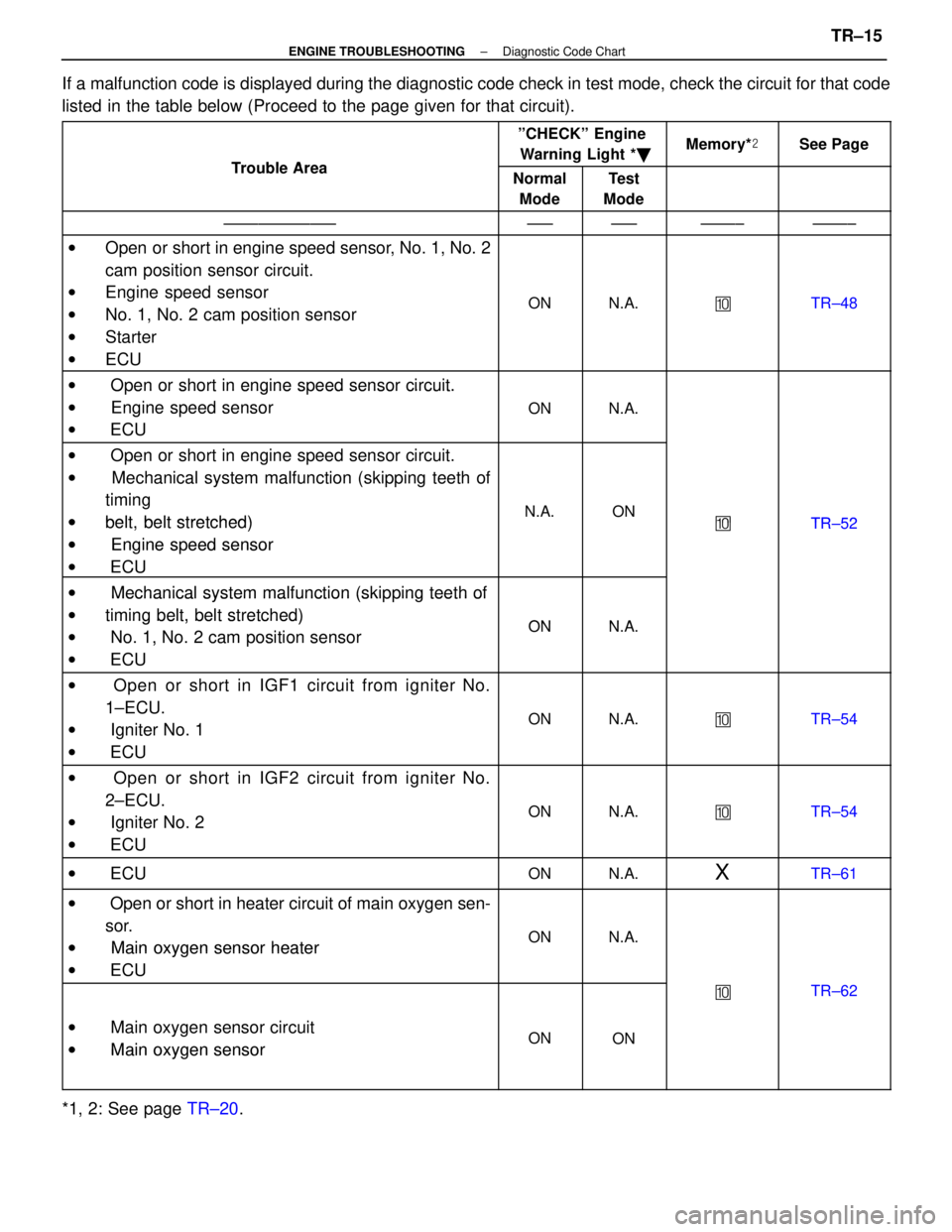
If a malfunction code is displayed during the diagnostic code check in tes\
t mode, check the circuit for that code
listed in the table below (Proceed to the page given for that circuit).
Tro ble Area
ºCHECKº EngineWarning Light * �Memory*�See Page
Trouble AreaNormal
ModeTest
Mode
±±±±±±±±±±±±±±±±±±±±±±±±±±±±±
w Open or short in engine speed sensor, No. 1, No. 2
cam position sensor circuit.
w Engine speed sensor
w No. 1, No. 2 cam position sensor
w Starter
w ECU
ONN.A.�TR±48
w Open or short in engine speed sensor circuit.w Oen or short in engine s eed sensor circuit.
w Engine speed sensor
ONN.A. Engine s eed sensor
w ECU
ONN.A.
w Open or short in engine speed sensor circuit.g
w Mechanical system malfunction (skipping teeth of
ti itiming
wbelt belt stretched)N.A.ON�TR 52wbelt, belt stretched)
wEngine speed sensor
�TR±52
w Engine s eed sensor
w ECU
w Mechanical system malfunction (skipping teeth ofw Mechanical system malfunction (ski ing teeth of
wtiming belt, belt stretched)ONNAwtiming belt, belt stretched)
w No. 1, No. 2 cam position sensorONN.A. No. 1, No. 2 cam osition sensor
w ECU
w Open or short in IGF1 circuit from igniter No.
1±ECU.
w Igniter No. 1
w ECU
ONN.A.�TR±54
w Open or short in IGF2 circuit from igniter No.
2±ECU.
w Igniter No. 2
w ECU
ONN.A.�TR±54
w ECUONN.A.XTR±61
w Open or short in heater circuit of main oxygen sen-
sor.
w Main oxygen sensor heaterONN.A.w Main oxygen sensor heater
w ECU
�TR±62
w Main oxygen sensor circuit
w
Main oxygen sensorONONw Main oxygen sensor
*1, 2: See page TR±20.
±
ENGINE TROUBLESHOOTING Diagnostic Code ChartTR±15
WhereEverybodyKnowsYourName
Page 2628 of 4087

ºCHECKº Engine
Tro ble Area
CHECK Engine
Warning Light *�Memory*�See PageTrouble AreaNormal
ModeTest
ModeMemory* �See Page
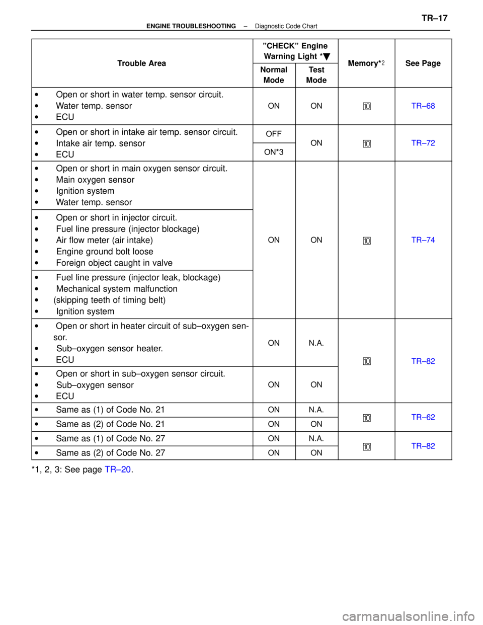
w Open or short in water temp. sensor circuit.
w Water temp. sensor
w ECU
ONON�TR±68
w Open or short in intake air tempsensor circuitOFFw Open or short in intake air temp. sensor circuit.
w Intake air tempsensor
OFF
ON�TR 72w Intake air temp. sensor
ECUON*3
ON�TR±72
w ECUON*3
w Open or short in main oxygen sensor circuit.w Oen or short in main oxygen sensor circuit.
w Main oxygen sensor
Main oxygen sensor
w Ignition systemgy
w Water temp. sensor
w Open or short in injector circuit.w Oen or short in injector circuit.
w Fuel line pressure
(injector blockage)w Fuel line ressure (injector blockage)
w Air flow meter (air intake)ONON�TR±74 Air flow meter (air intake)
w Engine ground bolt loose
�
gg
w Foreign object caught in valve
w Fuel line pressure (injector leak, blockage)w Fuel line ressure (injector leak, blockage)
w Mechanical system malfunction Mechanical system malfunction
w(skipping teeth of timing belt)(g g)
w Ignition system
w Open or short in heater circuit of sub±oxygen sen-
sor.
w Sub±oxygen sensor heaterONN.A.w Sub±oxygen sensor heater.
w ECU
�TR±82
w Open or short in sub±oxygen sensor circuit.
�TR 82
w Oen or short in sub oxygen sensor circuit.
w Sub±oxygen sensor
ONON Sub oxygen sensor
w ECU
w Same as (1) of Code No. 21ONN.A.
�TR 62w Same as (2) of Code No. 21ONON�TR±62
w Same as (1) of Code No. 27ONN.A.
�TR 82w Same as (2) of Code No. 27ONON�TR±82
*1, 2, 3: See page TR±20.
±
ENGINE TROUBLESHOOTING Diagnostic Code ChartTR±17
WhereEverybodyKnowsYourName
Page 2673 of 4087

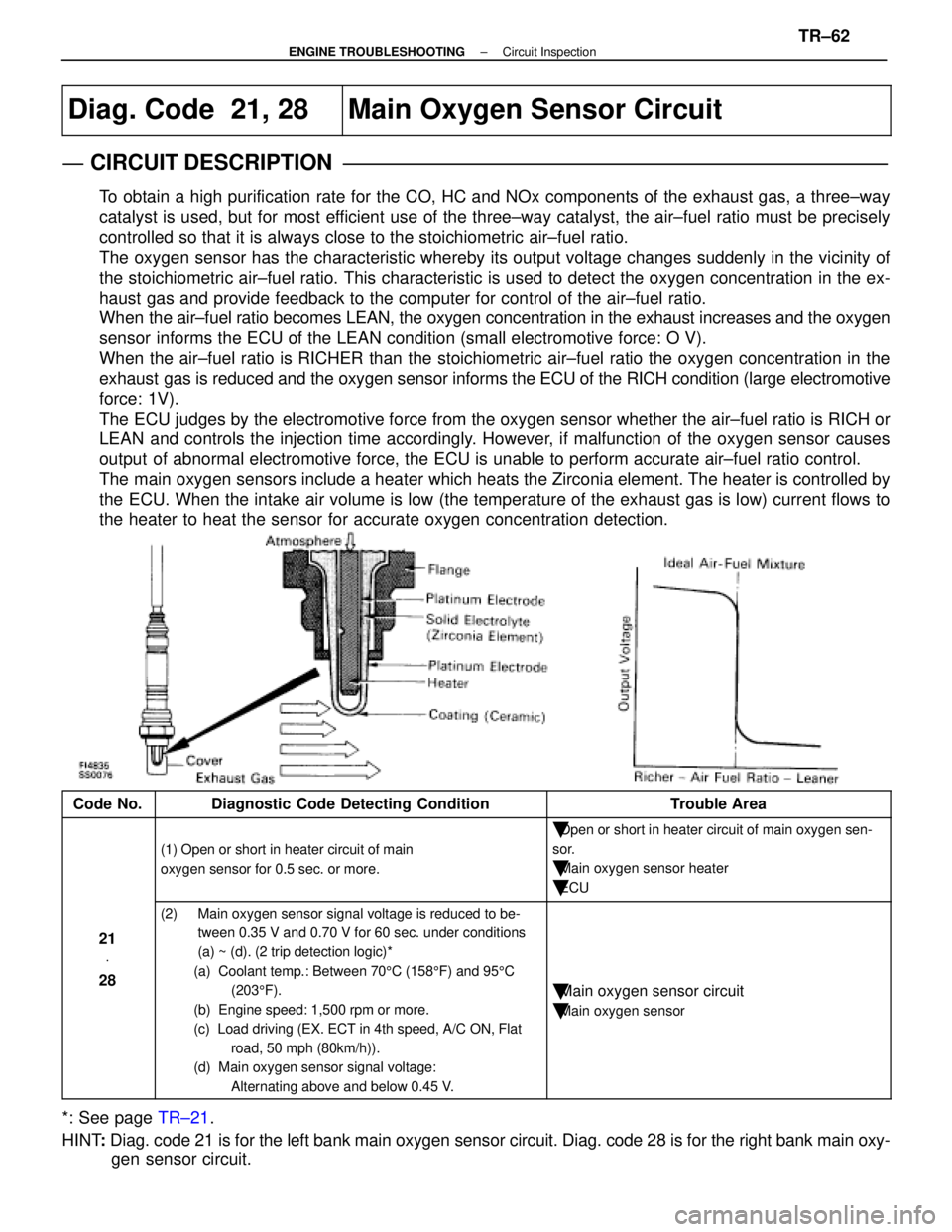
Diag. Code 21, 28Main Oxygen Sensor Circuit
CIRCUIT DESCRIPTION
To obtain a high purification rate for the CO, HC and NOx components of th\
e exhaust gas, a three±way
catalyst is used, but for most efficient use of the three±way catalyst, the air±fuel ratio must be \
precisely
controlled so that it is always close to the stoichiometric air±fuel \
ratio.
The oxygen sensor has the characteristic whereby its output voltage chan\
ges suddenly in the vicinity of
the stoichiometric air±fuel ratio. This characteristic is used to det\
ect the oxygen concentration in the ex-
haust gas and provide feedback to the computer for control of the air±\
fuel ratio.
When the air±fuel ratio becomes LEAN, the oxygen concentration in the exh\
aust increases and the oxygen
sensor informs the ECU of the LEAN condition (small electromotive force: O V)\
.
When the air±fuel ratio is RICHER than the stoichiometric air±fuel\
ratio the oxygen concentration in the
exhaust gas is reduced and the oxygen sensor informs the ECU of the RICH condition (large electromotive
force: 1V).
The ECU judges by the electromotive force from the oxygen sensor whether th\
e air±fuel ratio is RICH or
LEAN and controls the injection time accordingly. However, if malfunction of the oxygen sensor causes
output of abnormal electromotive force, the ECU is unable to perform accurate \
air±fuel ratio control.
The main oxygen sensors include a heater which heats the Zirconia element. The heater is controlled by
the ECU. When the intake air volume is low (the temperature of the exhaust\
gas is low) current flows to
the heater to heat the sensor for accurate oxygen concentration detectio\
n.
Code No.Diagnostic Code Detecting ConditionTrouble Area
(1) Open or short in heater circuit of main
oxygen sensor for 0.5 sec. or more.
�Open or short in heater circuit of main oxygen sen-
sor.
�Main oxygen sensor heater
�ECU
21 V
28
(2) Main oxygen sensor signal voltage is reduced to be-
tween 0.35 V and 0.70 V for 60 sec. under conditions
(a) ~ (d). (2 trip detection logic)*
(a) Coolant temp.: Between 70 5C (158 5F) and 95 5C
(203 5F).
(b) Engine speed: 1,500 rpm or more.
(c) Load driving (EX. ECT in 4th speed, A/C ON, Flat road, 50 mph (80km/h)).
(d) Main oxygen sensor signal voltage:
Alternating above and below 0.45 V.
�Main oxygen sensor circuit
�Main oxygen sensor
*: See page TR±21.
HINT : Diag. code 21 is for the left bank main oxygen sensor circuit. Diag. co\
de 28 is for the right bank main oxy-
gen sensor circuit.
±
ENGINE TROUBLESHOOTING Circuit InspectionTR±62
WhereEverybodyKnowsYourName
Page 2675 of 4087
DIAGNOSTIC CHART
DIAGNOSTIC
CHART
WIRING DIAGRAM
HINT: If diag. code º21º is output, check the left bank main oxygen sens\
or circuit. If diag. code º28º is output, check the right bank main oxygen sensor circuit.
Check voltage of terminals HTL1, HTR1.
Check resistance of oxygen sensor heater.
Check and repair oxygen sensor heater circuit.
Check operation of oxygen sensor heater.
Check and replace ECU. Replace main oxygen sensor.
*: In this case, oxygen sensor can be deteriorated.
Replace main oxygen sensor.*
±
ENGINE TROUBLESHOOTING Circuit InspectionTR±64
WhereEverybodyKnowsYourName