Page 2420 of 4087
 Install the three gaskets to the timing belt cover.
(b) Install the cord grommet to the")
8. INSTALL VSV FOR EVAP SYSTEMInstall the VSV with the two bolts.
9. INSTALL LH NO.3 TIMING BELT COVER (a) Install the three gaskets to the timing belt cover.
(b) Install the cord grommet to the high±tension cord.
(c) Install the cord grommet to the timing belt cover.
(d) Fit portion A of the timing belt cover, matching it with the
lower high±tension cord cover.
(e) Install the timing belt cover with the four bolts.
10. INSTALL RH ENGINE WIRE COVER (a) Fit portions A and B of the engine wire cover, matching
them with the lower high±tension cord cover and No.3
timing belt cover.
(d) Install the engine wire cover with the bolt.
11. INSTALL LH ENGINE WIRE COVER (a) Connect portions A and B engine wire cover to the wirebrackets.
(b) Set the VSV (for fuel pressure control system) wire in original position.
(c) Fit portions C and D of the engine wire cover, matching them with the lower high±tension cord cover and No.3
timing belt cover.
(d) Install the engine wire cover with the two bolts.
12. INSTALL UPPER HIGH±TENSION CORD COVER (a) Fit portion A of the upper high±tension cover, matching
it with the top of the lower high±tension cord cover.
FI±40
EFI SYSTEM
± Fuel System (Cold Start Injector)
WhereEverybodyKnowsYourName
Page 2440 of 4087

1. INSTALL FUEL PRESSURE PULSATION DAMPER Using SST, install two new gaskets, the inlet hose and pulsa-
tion damper.
SS")
INSTALLATION OF FUEL PRESSURE
PULSATION DAMPER
(See Components on page FI±58)
1. INSTALL FUEL PRESSURE PULSATION DAMPER Using SST, install two new gaskets, the inlet hose and pulsa-
tion damper.
SST 09612±24014 (09617±24011)
Torque: 39 N Vm (400 kgf Vcm, 29 ft Vlbf)
33 N Vm (340 kgf Vcm, 24 ft Vlbf) for SST
HINT: Use a torque wrench with a fulcrum length of 30 cm
(11.81 in.)
2. INSTALL LH ENGINE WIRE COVER
(a) Connect portions A and B engine wire cover to the wirebrackets.
(b) Set the VSV (for fuel pressure control system) wire in original position.
(c) Fit portions C and D of the engine wire cover, matching them with the lower high±tension cord cover and No.3
timing belt cover.
(d) Install the engine wire cover with the two bolts.
3. INSTALL UPPER HIGH±TENSION CORD COVER (a) Fit portion A of the upper high±tension cover, matching
it with the top of the lower high±tension cord cover.
(b) Push the front side of the high±tension cord cover, and connect the front side claw groove of the upper
high±tension cord cover to the claw of the lower
high±tension cord cover.
(c) Install the upper high±tension cord cover with the two bolts.
4. CONNECT CABLE TO NEGATIVE TERMINAL OF BATTERY
5. CHECK FOR FUEL LEAKS (See page FI±16)
FI±60
EFI SYSTEM
± Fuel System (Fuel Pressure Pulsation Damper)
WhereEverybodyKnowsYourName
Page 2461 of 4087
COMPONENTS
REMOVAL OF ISC VALVE
1. REMOVE LOWER HIGH±TENSION CORD COVER(See steps 1, 2 and 5 to 12 on pages FI±27 to 29)
2. REMOVE ISC VALVE
(a) Disconnect the ISC valve connector.
(b) (USA Spec.)Remove the bolt holding the water by±pass pipe (be-
tween ISC valve and EGR valve) to the air intake cham-
ber.
(c) (Exc. USA Spec.) Remove the bolt holding the water by±pass pipe (be-
tween ISC valve and EGR valve) to the VSV (for fuel
pressure control). FI±81
EFI SYSTEM
± Air Induction System (Idle Speed Control (ISC) Valve)
WhereEverybodyKnowsYourName
Page 2463 of 4087
INSTALLATION OF ISC VALVE
(See Components on page FI±81)
1. INSTALL ISC VALVE (a) Install a new gasket and the ISC valve with the two nuts.
Torque: 18 N Vm (185 kgf Vcm, 13 ft Vlbf)
(b) Connect the following hoses to the ISC valve:
(1) Water by±pass hose (from throttle valve)
(2) Water by±pass hose (from water inlet housing)
(3) Water by±pass hose (from EGR valve)
(c) (USA Spec.) Install the vacuum pipe and water by±pass pipe (be-
tween ISC valve and EGR valve) to the air intake cham-
ber with the bolt.
(d) (Exc. USA Spec.) Install the water by±pass pipe (between ISC valve and
EGR valve) to the VSV (for fuel pressure control) with
the bolt.
(e) Connect the ISC valve connector.
1. INSTALL LOWER HIGH±TENSION CORD COVER (See steps 5 to 13 and 16 to 18 on pages FI±39 to 41)FI±83
EFI SYSTEM
± Air Induction System (Idle Speed Control (ISC) Valve)
WhereEverybodyKnowsYourName
Page 2470 of 4087
VSV for Fuel Pressure Control
FI±90 ± Electronic Control System (VSV for Fue\
l Pressure Control)EFI SYSTEM
WhereEverybodyKnowsYourName
Page 2471 of 4087
COMPONENTS FOR REMOVAL AND INSTALLATION
FI±91EFI SYSTEM ± Electronic Control System (VSV for Fuel Pressure Control)
WhereEverybodyKnowsYourName
Page 2472 of 4087
INSPECTION OF VSV FOR FUEL
PRESSURE CONTROL
1. DISCONNECT CABLE FROM NEGATIVE TERMINAL OFBATTERY
CAUTION: Work must be started after approx. 20 se-
conds or longer from the time the ignition switch is
turned to the ºLOCKº position and the negative (±) termi-
nal cable is disconnected from the battery.
2. REMOVE VSV (a) Disconnect the VSV connector.
(b) Disconnect the following hoses from VSV:(1) Vacuum hose (from fuel pressure regulator)
(2) Vacuum hose (from air intake chamber)
(c) (Exc. USA Spec.) Remove the bolt holding the water by±pass pipe to the
VSV.
(d) Remove the bolt and VSV.
FI±92
EFI SYSTEM
± Electronic Control System (VSV for Fuel Pressure Control)
WhereEverybodyKnowsYourName
Page 2473 of 4087
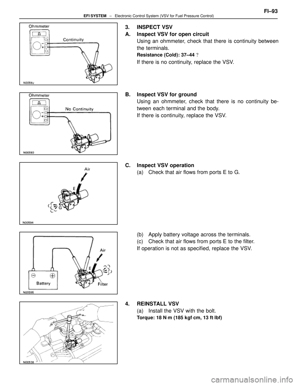
3. INSPECT VSV
A. Inspect VSV for open circuitUsing an ohmmeter, check that there is continuity between
the terminals.
Resistance (Cold): 37±44 �
If there is no continuity, replace the VSV.
B. Inspect VSV for ground Using an ohmmeter, check that there is no continuity be-
tween each terminal and the body.
If there is continuity, replace the VSV.
C. Inspect VSV operation (a) Check that air flows from ports E to G.
(b) Apply battery voltage across the terminals.
(c) Check that air flows from ports E to the filter.
If operation is not as specified, replace the VSV.
4. REINSTALL VSV (a) Install the VSV with the bolt.
Torque: 18 N Vm (185 kgf Vcm, 13 ft Vlbf)
FI±93EFI SYSTEM ± Electronic Control System (VSV for Fuel Pressure Control)
WhereEverybodyKnowsYourName

2. REMOVE ISC VALVE
(a) Disconnect the ISC valve connector.
(b) (USA Spe")

1. INSTALL ISC VALVE (a) Install a new gasket and the ISC valve with the two nuts.
Torque: 18 N Vm (185 kgf Vcm, 13 ft Vlbf)
(b) Connect t")
EFI SYSTEM
WhereEverybodyKnowsYourName")

WhereEverybodyKnowsYourName")