Page 2237 of 4087
10. REMOVE RH ENGINE WIRE COVERRemove the bolt and engine wire cover.
11. REMOVE LH ENGINE WIRE COVER Remove the two bolts and engine wire cover.
12. REMOVE VSV FOR EVAP SYSTEM Remove the two bolts, and disconnect the VSV from cylinder
head and timing belt cover.
13. REMOVE NO.3 TIMING BELT COVER Remove the three bolts and timing belt cover.
14. REMOVE LH NO.3 TIMING BELT COVER (a) Remove the four mounting bolts.
(b) Disconnect the cord grommet from the timing belt cover,
and remove the timing belt cover.
(c) Remove the cord grommet from the high±tension cord.
±
ENGINE MECHANICAL Timing BeltEM±37
WhereEverybodyKnowsYourName
Page 2254 of 4087

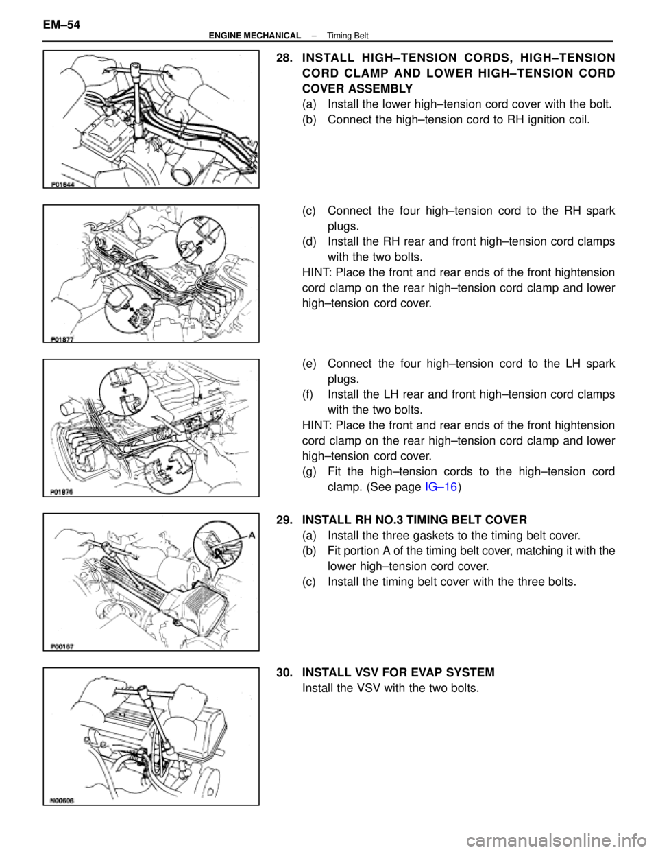
28. INSTALL HIGH±TENSION CORDS, HIGH±TENSIONCORD CLAMP AND LOWER HIGH±TENSION CORD
COVER ASSEMBLY
(a) Install the lower high±tension cord cover with the bolt.
(b) Connect the high±tension cord to RH ignition coil.
(c) Connect the four high±tension cord to the RH sparkplugs.
(d) Install the RH rear and front high±tension cord clamps
with the two bolts.
HINT: Place the front and rear ends of the front hightension
cord clamp on the rear high±tension cord clamp and lower
high±tension cord cover.
(e) Connect the four high±tension cord to the LH spark plugs.
(f) Install the LH rear and front high±tension cord clamps
with the two bolts.
HINT: Place the front and rear ends of the front hightension
cord clamp on the rear high±tension cord clamp and lower
high±tension cord cover.
(g) Fit the high±tension cords to the high±tension cord clamp. (See page IG±16)
29. INSTALL RH NO.3 TIMING BELT COVER (a) Install the three gaskets to the timing belt cover.
(b) Fit portion A of the timing belt cover, matching it with the
lower high±tension cord cover.
(c) Install the timing belt cover with the three bolts.
30. INSTALL VSV FOR EVAP SYSTEM Install the VSV with the two bolts.
EM±54
±
ENGINE MECHANICAL Timing Belt
WhereEverybodyKnowsYourName
Page 2255 of 4087

31. INSTALL LH NO.3 TIMING BELT COVER(a) Install the three gaskets to the timing belt cover.
(b) Install the cord grommet to the high±tension cord.
(c) Install the cord grommet to the timing belt cover.
(d) Fit portion A of the timing belt cover, matching it with the
lower high±tension cord cover.
(e) Install the timing belt cover with the four bolts.
32. INSTALL RH ENGINE WIRE COVER (a) Fit portions A and B of the engine wire cover, matchingthem with the lower high±tension cord cover and No. 3
timing belt cover.
(b) Install the engine wire cover with the bolt.
33. INSTALL LH ENGINE WIRE COVER (a) Connect portions A and B of the engine wire cover to the
wire cover brackets.
(b) Set the VSV (for Fuel pressure control system) wire in original position.
(c) Fit portions C and D of the engine wire cover, matching them with the lower high±tension cord cover and No.3
timing belt cover.
(b) Install the engine wire cover with the two bolts.
34. INSTALL UPPER HIGH±TENSION CORD COVER (a) Fit portion A of the upper high±tension cover, matchingit with the top of the lower high±tension cord cover.
(b) Push the front side of the high±tension cord cover, and connect the front side claw groove of the upper
high±tension cord cover to the claw of the lower
high±tension cord cover.
(c) Install the upper high±tension cord cover with the two bolts.
±
ENGINE MECHANICAL Timing BeltEM±55
WhereEverybodyKnowsYourName
Page 2262 of 4087
9. REMOVE TIMING BELT REAR PLATESRemove the two bolts and rear plate. Remove the two rear
plates.
10. REMOVE VACUUM PIPE (a) Disconnect the following hoses:(1) (USA Spec.)
Vacuum hose from throttle body
(2) (Exc. USA Spec.) Three vacuum hoses from throttle body
(3) Vacuum hose from fuel pressure regulator
(4) Two vacuum hoses from VSV for fuel pressure con-
trol system
(5) (Exc. USA Spec.) Two vacuum hoses from EGR vacuum modulator
(6) Two vacuum hoses (from VSV for EVAP system)
from vacuum pipe
(7) Vacuum hose (from VSV for fuel pressure control system) from air intake chamber
(8) Vacuum hose (from charcoal canister) from vacu-
um pipe.
(b) Remove the two bolts, the vacuum pipe and vacuum hoses assembly.
EM±62
±
ENGINE MECHANICAL Cylinder Heads
WhereEverybodyKnowsYourName
Page 2263 of 4087
11. (USA Spec.)REMOVE EGR VALVE
(a) Disconnect the EGR valve connector.
(b) Disconnect the following hoses:(1) Water by±pass pipe hose from ISC valve
(2) Water by±pass hose from water by±pass pipe (from rear water by±pass joint)
(c) Remove the two nuts, EGR valve and gasket.
12. (Exc. USA Spec.) REMOVE EGR VALVE AND VACUUM MODULATOR
(a) Disconnect the hose clamp (A) from the PCV hose.
(b) Disconnect the following hoses:(1) Water by±pass pipe hose from ISC valve
(2) Water by±pass hose from water by±pass pipe (from rear water by±pass joint)
(3) Two vacuum hoses from VSV for EGR system
(c) Remove the bolt, two nuts, the EGR valve, vacuum modulator assembly and gasket.
13. REMOVE EGR VALVE ADAPTOR (a) Disconnect the PCV hose from the cylinder head.
±
ENGINE MECHANICAL Cylinder HeadsEM±63
WhereEverybodyKnowsYourName
Page 2264 of 4087
(b) Remove the two bolts, two nuts, adaptor and gasket.
(c) (USA Spec. only)Disconnect the EGR gas temperature sensor connec-
tor.
14. REMOVE ISC VALVE (a) Disconnect the ISC valve connector.
(b) Disconnect the water by±pass hose from the ISC valve.
(c) Remove the two nuts, ISC valve and gasket.
15. DISCONNECT HEATER WATER VALVE FROM BODY (a) Disconnect the VSV connector.
(b) Remove the bolt holding the engine wire clamp to thewater valve bracket.
(c) Remove the two bolts, and disconnect the water valve and bracket assembly.
16. REMOVE THROTTLE BODY (a) Disconnect the following connectors:(1) Throttle position sensor connector
(2) (w/ TRAC)
Sub±throttle position sensor connector
(3) (w/ TRAC) Sub±throttle actuator connector
EM±64
±
ENGINE MECHANICAL Cylinder Heads
WhereEverybodyKnowsYourName
Page 2265 of 4087

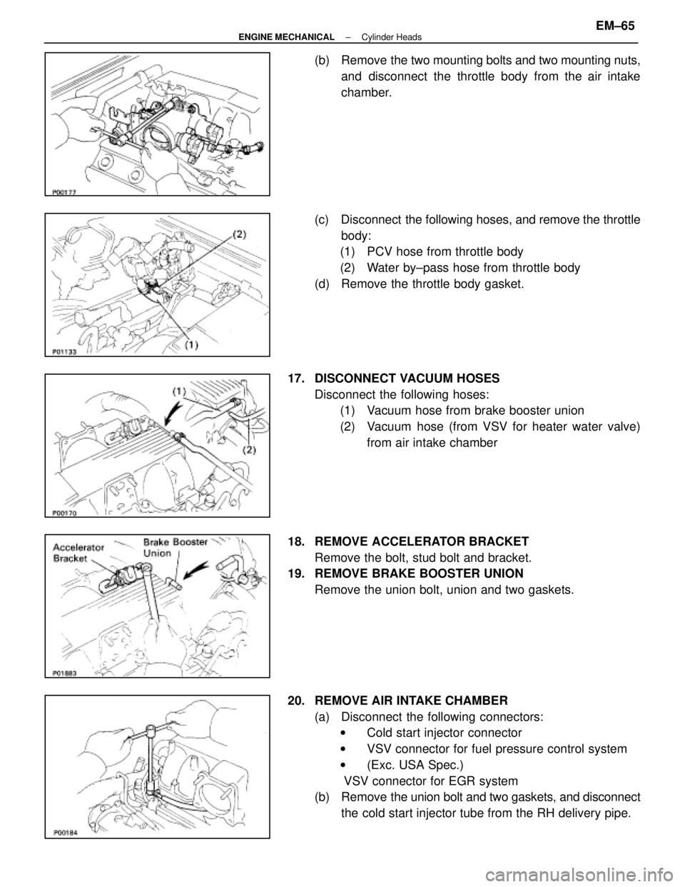
(b) Remove the two mounting bolts and two mounting nuts,and disconnect the throttle body from the air intake
chamber.
(c) Disconnect the following hoses, and remove the throttle body:
(1) PCV hose from throttle body
(2) Water by±pass hose from throttle body
(d) Remove the throttle body gasket.
17. DISCONNECT VACUUM HOSES Disconnect the following hoses:(1) Vacuum hose from brake booster union
(2) Vacuum hose (from VSV for heater water valve)
from air intake chamber
18. REMOVE ACCELERATOR BRACKET Remove the bolt, stud bolt and bracket.
19. REMOVE BRAKE BOOSTER UNION
Remove the union bolt, union and two gaskets.
20. REMOVE AIR INTAKE CHAMBER (a) Disconnect the following connectors:w Cold start injector connector
w VSV connector for fuel pressure control system
w (Exc. USA Spec.)
VSV connector for EGR system
(b) Remove the union bolt and two gaskets, and disconnect
the cold start injector tube from the RH delivery pipe.
±
ENGINE MECHANICAL Cylinder HeadsEM±65
WhereEverybodyKnowsYourName
Page 2266 of 4087
(c) Remove the two bolts and gaskets, and disconnect theEGR pipe from the air intake chamber.
(d) Remove the four mounting bolts, eight mounting nuts and following parts:
(1) VSV for fuel pressure control system
(2) (Exc. USA Spec.)
VSV for EGR system
(3) A/T throttle cable bracket
(e) Disconnect the check (ºDIAGNOSISº) connector from
the intake chamber.
(f) Remove the air intake chamber and four gaskets.
(g) Remove the three bolts, the cold start injector, tube, lead
wire assembly and gasket.
21. DISCONNECT HEATER WATER HOSES Disconnect the following hoses:(1) Water hose from water by±pass pipe
(2) Water hose from rear water by±pass joint
22. DISCONNECT FUEL INLET HOSE FROM LH DELIVERY PIPE
Remove the pulsation damper and two gaskets, and discon-
nect the inlet hose.
23. D I S C O N N E C T F U E L R E T U R N H O S E F R O M F U E L RETURN PIPE
EM±66
±
ENGINE MECHANICAL Cylinder Heads
WhereEverybodyKnowsYourName