Page 2061 of 4087
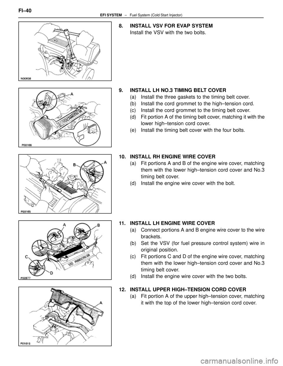
8. INSTALL VSV FOR EVAP SYSTEMInstall the VSV with the two bolts.
9. INSTALL LH NO.3 TIMING BELT COVER (a) Install the three gaskets to the timing belt cover.
(b) Install the cord grommet to the high±tension cord.
(c) Install the cord grommet to the timing belt cover.
(d) Fit portion A of the timing belt cover, matching it with the
lower high±tension cord cover.
(e) Install the timing belt cover with the four bolts.
10. INSTALL RH ENGINE WIRE COVER (a) Fit portions A and B of the engine wire cover, matching
them with the lower high±tension cord cover and No.3
timing belt cover.
(d) Install the engine wire cover with the bolt.
11. INSTALL LH ENGINE WIRE COVER (a) Connect portions A and B engine wire cover to the wirebrackets.
(b) Set the VSV (for fuel pressure control system) wire in original position.
(c) Fit portions C and D of the engine wire cover, matching them with the lower high±tension cord cover and No.3
timing belt cover.
(d) Install the engine wire cover with the two bolts.
12. INSTALL UPPER HIGH±TENSION CORD COVER (a) Fit portion A of the upper high±tension cover, matching
it with the top of the lower high±tension cord cover.
FI±40
EFI SYSTEM
± Fuel System (Cold Start Injector)
WhereEverybodyKnowsYourName
Page 2100 of 4087
6. REMOVE VSV FOR EVAP SYSTEMRemove the two bolts, and disconnect the VSV from cylinder
head and timing belt cover.
7. REMOVE RH NO.3 TIMING BELT COVER Remove the three bolts and timing belt cover.
8. REMOVE LH NO.3 TIMING BELT COVER (a) Remove the four mounting bolts.
(b) Disconnect the cord grommet from the timing belt cover,
and remove the timing belt cover.
(c) Remove the cord grommet from the high±tension cord.
9. REMOVE HIGH±TENSION CORDS (a) Disconnect the high±tension cords from the spark plugs
and distributor caps. Disconnect the high±tension cords
at the rubber boot. Do not pull on the cords.
NOTICE: Pulling on or bending the cords may damage
the conductor inside.
±
IGNITION SYSTEM High±Tension Cords and Cord ClampsIG±13
WhereEverybodyKnowsYourName
Page 2105 of 4087
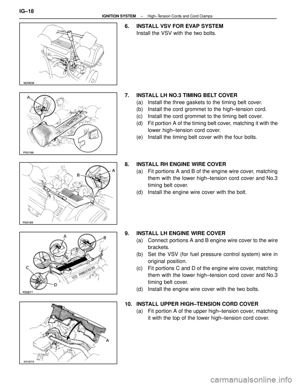
6. INSTALL VSV FOR EVAP SYSTEMInstall the VSV with the two bolts.
7. INSTALL LH NO.3 TIMING BELT COVER (a) Install the three gaskets to the timing belt cover.
(b) Install the cord grommet to the high±tension cord.
(c) Install the cord grommet to the timing belt cover.
(d) Fit portion A of the timing belt cover, matching it with the
lower high±tension cord cover.
(e) Install the timing belt cover with the four bolts.
8. INSTALL RH ENGINE WIRE COVER (a) Fit portions A and B of the engine wire cover, matchingthem with the lower high±tension cord cover and No.3
timing belt cover.
(d) Install the engine wire cover with the bolt.
9. INSTALL LH ENGINE WIRE COVER (a) Connect portions A and B engine wire cover to the wirebrackets.
(b) Set the VSV (for fuel pressure control system) wire in original position.
(c) Fit portions C and D of the engine wire cover, matching them with the lower high±tension cord cover and No.3
timing belt cover.
(d) Install the engine wire cover with the two bolts.
10. INSTALL UPPER HIGH±TENSION CORD COVER (a) Fit portion A of the upper high±tension cover, matchingit with the top of the lower high±tension cord cover.
IG±18
±
IGNITION SYSTEM High±Tension Cords and Cord Clamps
WhereEverybodyKnowsYourName
Page 2212 of 4087
6. REMOVE UPPER HIGH±TENSION CORD COVER(a) Remove the two mounting bolts.
(b) Disconnect the front side claw groove of the cord coverfrom the claw of the lower cover, and remove the cord
cover.
7. REMOVE RH ENGINE WIRE COVER Remove the bolt and engine wire cover.
8. REMOVE LH ENGINE WIRE COVER Remove the two bolts and engine wire cover.
9. REMOVE VSV FOR EVAP SYSTEM Remove the two bolts, and disconnect the VSV from cylinder
head and timing belt cover.
10. REMOVE RH NO.3 TIMING BELT COVER Remove the three bolts and timing belt cover.
EM±12
±
ENGINE MECHANICAL Engine Tune±Up
WhereEverybodyKnowsYourName
Page 2213 of 4087
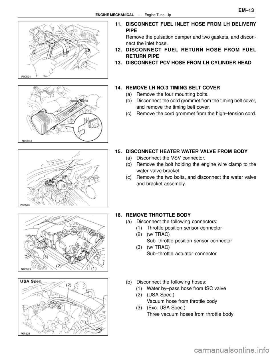
11. DISCONNECT FUEL INLET HOSE FROM LH DELIVERYPIPE
Remove the pulsation damper and two gaskets, and discon-
nect the inlet hose.
12. D I S C O N N E C T F U E L R E T U R N H O S E F R O M F U E L RETURN PIPE
13. DISCONNECT PCV HOSE FROM LH CYLINDER HEAD
14. REMOVE LH NO.3 TIMING BELT COVER (a) Remove the four mounting bolts.
(b) Disconnect the cord grommet from the timing belt cover,
and remove the timing belt cover.
(c) Remove the cord grommet from the high±tension cord.
15. DISCONNECT HEATER WATER VALVE FROM BODY (a) Disconnect the VSV connector.
(b) Remove the bolt holding the engine wire clamp to thewater valve bracket.
(c) Remove the two bolts, and disconnect the water valve and bracket assembly.
16. REMOVE THROTTLE BODY (a) Disconnect the following connectors:(1) Throttle position sensor connector
(2) (w/ TRAC)
Sub±throttle position sensor connector
(3) (w/ TRAC) Sub±throttle actuator connector
(b) Disconnect the following hoses: (1) Water by±pass hose from ISC valve
(2) (USA Spec.) Vacuum hose from throttle body
(3) (Exc. USA Spec.) Three vacuum hoses from throttle body
±
ENGINE MECHANICAL Engine Tune±UpEM±13
WhereEverybodyKnowsYourName
Page 2224 of 4087
(b) Install a new gasket and throttle body with the two boltsand two nuts.
Torque: 18 N Vm (185 kgf Vcm, 13 ft Vlbf)
HINT: Use bolts 40 mm (1.57 in.) in length.
(c) Install the water by±pass pipe (from rear water by±pass
joint) to the clamp on the engine wire cover.
(d) Connect the following hoses: (1) Water by±pass hose to the ISC valve
(2) (USA Spec.) Vacuum hose to throttle body
(3) (Exc. USA Spec.) Three vacuum hoses to throttle body
(e) Connect the following connectors: (1) Throttle position sensor connector
(2) (w/ TRAC) Sub±throttle position sensor connector
(3) (w/ TRAC) Sub±throttle actuator
27. REINSTALL HEATER WATER VALVE (a) Install the water valve and bracket assembly with thetwo bolts.
(b) Install the engine wire clamp with the bolt.
(c) Connect the VSV connector.
EM±24
±
ENGINE MECHANICAL Engine Tune±Up
WhereEverybodyKnowsYourName
Page 2225 of 4087
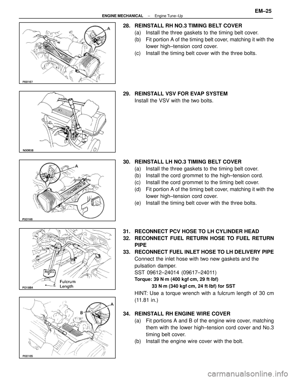
28. REINSTALL RH NO.3 TIMING BELT COVER(a) Install the three gaskets to the timing belt cover.
(b) Fit portion A of the timing belt cover, matching it with the
lower high±tension cord cover.
(c) Install the timing belt cover with the three bolts.
29. REINSTALL VSV FOR EVAP SYSTEM Install the VSV with the two bolts.
30. REINSTALL LH NO.3 TIMING BELT COVER (a) Install the three gaskets to the timing belt cover.
(b) Install the cord grommet to the high±tension cord.
(c) Install the cord grommet to the timing belt cover.
(d) Fit portion A of the timing belt cover, matching it with the
lower high±tension cord cover.
(e) Install the timing belt cover with the three bolts.
31. RECONNECT PCV HOSE TO LH CYLINDER HEAD
32. RECONNECT FUEL RETURN HOSE TO FUEL RETURN PIPE
33. RECONNECT FUEL INLET HOSE TO LH DELIVERY PIPE Connect the inlet hose with two new gaskets and the
pulsation damper.
SST 09612±24014 (09617±24011)
Torque: 39 N Vm (400 kgf Vcm, 29 ft Vlbf)
33 N Vm (340 kgf Vcm, 24 ft Vlbf) for SST
HINT: Use a torque wrench with a fulcrum length of 30 cm
(11.81 in.)
34. REINSTALL RH ENGINE WIRE COVER (a) Fit portions A and B of the engine wire cover, matchingthem with the lower high±tension cord cover and No.3
timing belt cover.
(b) Install the engine wire cover with the bolt.
±
ENGINE MECHANICAL Engine Tune±UpEM±25
WhereEverybodyKnowsYourName
Page 2226 of 4087
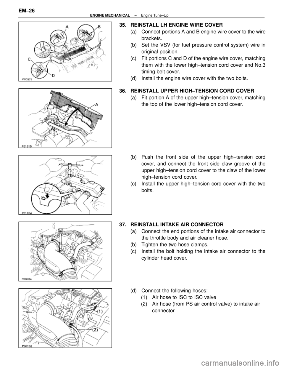
35. REINSTALL LH ENGINE WIRE COVER(a) Connect portions A and B engine wire cover to the wirebrackets.
(b) Set the VSV (for fuel pressure control system) wire in
original position.
(c) Fit portions C and D of the engine wire cover, matching them with the lower high±tension cord cover and No.3
timing belt cover.
(d) Install the engine wire cover with the two bolts.
36. REINSTALL UPPER HIGH±TENSION CORD COVER (a) Fit portion A of the upper high±tension cover, matchingthe top of the lower high±tension cord cover.
(b) Push the front side of the upper high±tension cord cover, and connect the front side claw groove of the
upper high±tension cord cover to the claw of the lower
high±tension cord cover.
(c) Install the upper high±tension cord cover with the two bolts.
37. REINSTALL INTAKE AIR CONNECTOR (a) Connect the end portions of the intake air connector tothe throttle body and air cleaner hose.
(b) Tighten the two hose clamps.
(c) Install the bolt holding the intake air connector to the cylinder head cover.
(d) Connect the following hoses: (1) Air hose to ISC to ISC valve
(2) Air hose (from PS air control valve) to intake air connector
EM±26
±
ENGINE MECHANICAL Engine Tune±Up
WhereEverybodyKnowsYourName