Page 1948 of 4087
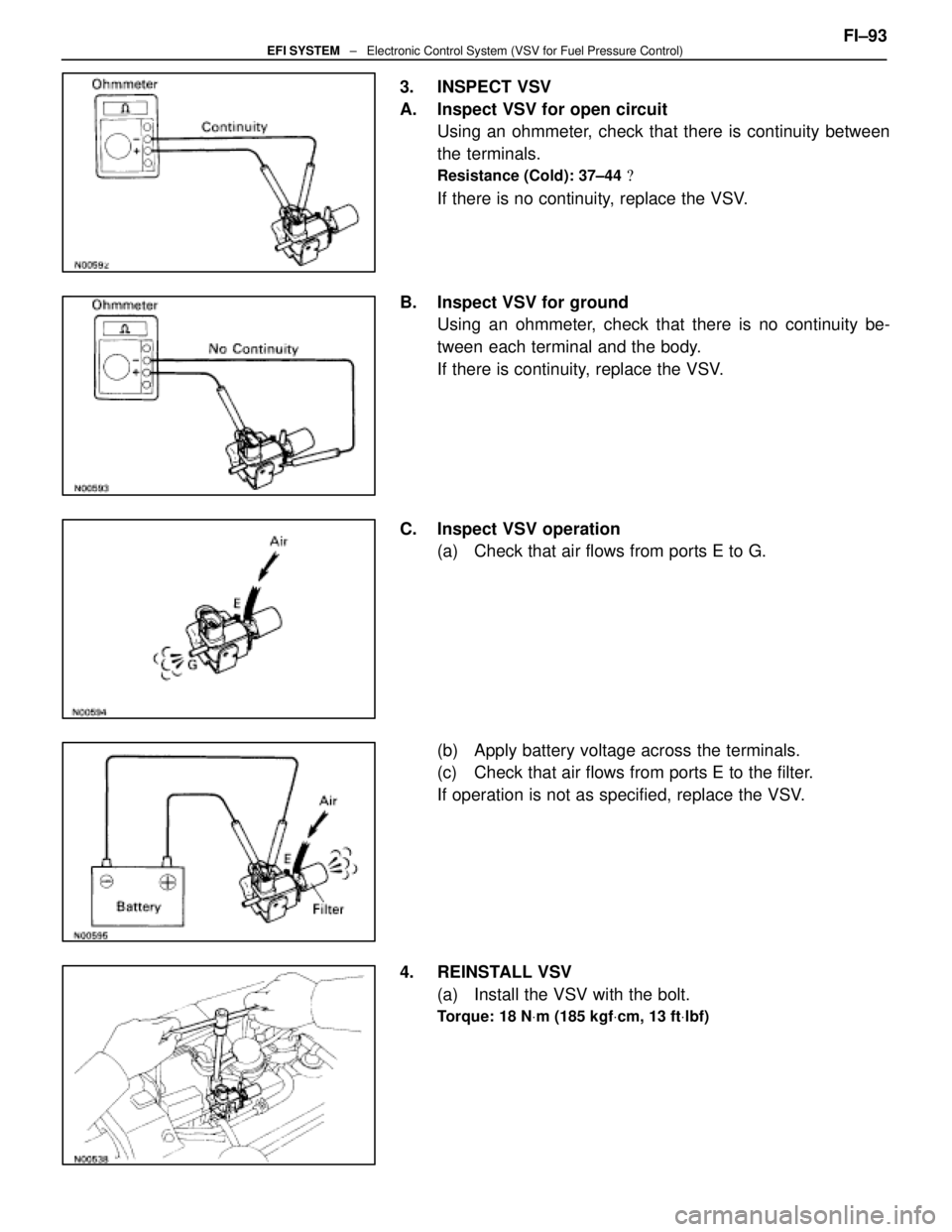
3. INSPECT VSV
A. Inspect VSV for open circuitUsing an ohmmeter, check that there is continuity between
the terminals.
Resistance (Cold): 37±44 �
If there is no continuity, replace the VSV.
B. Inspect VSV for ground Using an ohmmeter, check that there is no continuity be-
tween each terminal and the body.
If there is continuity, replace the VSV.
C. Inspect VSV operation (a) Check that air flows from ports E to G.
(b) Apply battery voltage across the terminals.
(c) Check that air flows from ports E to the filter.
If operation is not as specified, replace the VSV.
4. REINSTALL VSV (a) Install the VSV with the bolt.
Torque: 18 N Vm (185 kgf Vcm, 13 ft Vlbf)
FI±93EFI SYSTEM ± Electronic Control System (VSV for Fuel Pressure Control)
WhereEverybodyKnowsYourName
Page 1949 of 4087
(b) (Exc. USA Spec.)Install the water by±pass pipe to the VSV with the bolt.
(c) Connect the following hoses to VSV: (1) Vacuum hose (from fuel pressure regulator)
(2) Vacuum hose (from air intake chamber)
(d) Connect the VSV connector.
5. RECONNECT CABLE TO NEGATIVE TERMINAL OF BATTERY
FI±94
EFI SYSTEM
± Electronic Control System (VSV for Fuel Pressure Control)
WhereEverybodyKnowsYourName
Page 1950 of 4087
VSV for EVAP
INSPECTION OF VSV FOR EVAP
(See Emission Control System on page EC±11) FI±95
± Electronic Control System (VSV f\
or EVAP)EFI SYSTEM
WhereEverybodyKnowsYourName
Page 1951 of 4087
VSV for EGR (Exc. USA Spec.)
INSPECTION OF VSV FOR EGR
(See Emission Control Systems on page EC±18)
FI±96
± Electronic Control Syst\
em (VSV for EGR (Exc. USA Spec.))EFI SYSTEM
WhereEverybodyKnowsYourName
Page 1952 of 4087
EGR Valve (USA Spec. only)
INSPECTION OF VSV FOR EGR
(See Emission Control Systems on page EC±21) FI±97
± Electronic Control System (E\
GR Valve (USA Spec. Only))EFI SYSTEM
WhereEverybodyKnowsYourName
Page 1984 of 4087

TerminalNo.SymbolConnectionTerminalNo.SymbolConnection
E10± 21NCOT/M Input Speed SensorE10 ± 51±
22±52HTL2LH Sub±Oxygen Sensor Heater
23SP2No.2 Speed Senso")
TERMINALS OF ENGINE & ECT ECU (Cont'd)
TerminalNo.SymbolConnectionTerminalNo.SymbolConnection
E10± 21NCOT/M Input Speed SensorE10 ± 51±
22±52HTL2LH Sub±Oxygen Sensor Heater
23SP2No.2 Speed Sensor for ECT53HTR2RH Sub±Oxygen Sensor Heater
24±54±
25G2LH (No.2) Cam Position Sensor55±
26G1RH (No.1) Cam Position Sensor56IGT2No.2 Igniter for RH Bank
27NEEngine Speed Sensor57IGT1No.1 Igniter for LH Bank
28VF2Check Connector58IGF1No.1 Igniter for LH Bank
29VF1Check Connector59IGF2No.2 Igniter for RH Bank
30±60±
31±61±
32ISC4ISC Valve62±
33ISC3ISC Valve63IDL2Sub±Throttle Position Sensor
34ISC2ISC Valve64IDL1Throttle Position Sensor
35ISC1ISC Valve65E2Sensor Ground
36*� EGR4EGR Valve66KSAir Flow Meter
37*� EGR3EGR Valve67OXR2
38*� EGR2EGR Valve68OXL2LH Sub±Oxygen Sensor
39*� EGR1EGR Valve69E1ECU Ground39*� EGRVSV for EGR69E1ECU Ground
40±70±
41VCThrottle Position Sensor
Air Flow Meter71HTL1LH Main Oxygen Sensor
42VTA2Fuel Pump ECU72HTR1RH Main Oxygen Sensor
43VTA1A/C Magnet Clutch Relay73FPUVSV for Fuel Pressure Control
Value
44THWWater Temp. Sensor74*� PA GVSV for EVAP
45THAIntake Air Temp. Sensor75±
46THGEGR Gas Temp. Sensor76NSWNeutral Start Switch
47OXR1RH Main Oxygen Sensor77STAStarter Relay
48OXL1LH Main Oxygen Sensor78STJCold Start Injector
49KNK2RH (No.2) Knock Sensor79E02Power Ground
50KNK1LH (No.1) Knock Sensor80E01Power Ground
Engine & ECT ECU Terminals
*��USA spec. only
* �� A/T only
FI±127EFI SYSTEM ± Electronic Control System (Engine & ECT ECU)
WhereEverybodyKnowsYourName
Page 1994 of 4087

SERVICE SPECIFICATIONS
SERVICE DATA
Fuel pumpResistance0.2 ± 3.0 �
Cold start
injectorResistance
Fuel leakage2 ± 4 �
One drop or less per minute
Fuel pressure
regulatorFuel pressureat no vacuum265 ± 304 kPa
(2.7 ± 3.1 kgf/cm2, 38 ± 44 psi)
InjectorResistance
Injection volume
Difference between each cylinder
Fuel leakage13.4 ± 14.2 �
55 ± 70 cc (3.4 ± 4.3 cu in.) per 15 sec.
10 cc (0.6 cu in.) or less
One drop or less per minute
Air flow meterResistance (THA ± E2)at±20 °C (±4 °F)
at 0 °C (32 °F)
at 20 °C (68 °F)
at 40 °C (104 °F)
at 60 °C (140 °F)
at 80 °C (176 °F)10 ± 20 k �
4 ± 7 k �
2 ± 7 k �
0.9 ± 1.3 k �
0.4 ± 0.7 k �
0.2 ± 0.4 k �
Throttle bodyThrottle body fully closed angle6°
Throttle
positionClearance between
stop screw and leverBetween terminalsResistance
sensor
(main)0 mm
0.40 mm
0.65 mm0 in.
0.016 in.
0.026 in.VTA1 ± E2 IDL1 ± E2
IDL1 ± E2
VTA1 E2
0.2 ± 0.8 k �
2.3 k � or less
Infinity
33 100k �Throttle valve fully opened position
±VTA1 ± E2VC ± E2
y
3.3 ± 10.0 k �
4.0 ± 9.0 k �
Sub±throttle
positionClearance between
stop screw and leverBetween terminalsResistance
sensor
(w/ TRAC)0 mm
0.30 mm
0.50 mm0 in.
0.012 in.
0.020 in.VTA2 ± E2 IDL2 ± E2
IDL2 ± E2
VTA2 E2
0.2 ± 0.8 k �
2.3 k � or less
Infinity
33 100k �Throttle valve fully opened position
±VTA2 ± E2VC ± E2
y
3.3 ± 10.0 k �
4.0 ± 9.0 k �
Sub±throttle
actuator
(w/ TRAC)Resistance (ACM ± A and A, BCM ± B and B)0.5 ± 1.0 �
ISC valveResistance (B1 ± S1 and S3, B2 ± S2 and S4)10 ± 30 �
Cold start
injector time
switchResistance STA ± STJ below 15 °C (59 °F)
above 30 °C (86 °F)
STA ± Ground25 ± 45 �
65 ± 85
25 ± 85 �
VSV for fuel
pressure
controlResistance37 ± 44 �
FI±137 ± Service SpecificationsEFI SYSTEM
WhereEverybodyKnowsYourName
Page 2007 of 4087

AIR INDUCTION SYSTEM
Air filtered through the air cleaner passes through the air flow meter a\
nd the amount flowing to the air intake
chamber is determined by the throttle valve opening in the throttle body and th\
e engine rpm.
Air flow meter measures the air intake flow to the engine by the swirl f\
requency.
Located in the throttle body is the throttle valve, which regulates the \
volume of air intake to the engine. Air
intake controlled by the throttle valve opening is distributed from the \
intake chamber to the manifold of each
cylinder and is drain into the combustion chamber.
At low air temperature the ISC valve opens and the air flows through the I\
SC valve, as well as the throttle body,
into the air intake chamber. During engine warm up, the fast idle is accomplished by air flowing into the intake
chamber via ISC valve, even when the throttle valve is completely closed.
The air intake chamber prevents pulsation of the intake air, reduces the influence on the air flow meter and
increases the air intake volume. It also prevents intake air interferenc\
e in each cylinder.
There is also the Int ake Air Control Valve (IACV) attached to the air intake chamber. Part of the Acoustic Control
Induction System (ACIS), the ECU provides signals to the Vacuum Switch Valve (VSV) to open or close. This
valve opens or closes, the vacuum source to the actuator, which in turn opens or closes the IACV. The IACV
is designed to modify the effective manifold length in two stages for increased power in all driving\
ranges.
±
EFI SYSTEM OperationFI±7
WhereEverybodyKnowsYourName
 (Exc. USA Spec.)Install the water by±pass pipe to the VSV with the bolt.
(c) Connect the following hoses to VSV: (1) Vacuum hose (from fuel pressure regulator)
(2) Vacuum hose (from air inta")
 FI±95
± Electronic Control System (VSV f\
or EVAP)EFI SYSTEM
WhereEverybodyKn")

INSPECTION OF VSV FOR EGR
(See Emission Control Systems on page EC±18)
FI±96
± Electronic Control Syst\
em (VSV for EGR (Ex")

INSPECTION OF VSV FOR EGR
(See Emission Control Systems on page EC±21) FI±97
± Electronic Control System (E\
GR Valve (USA Spec. On")