Page 2308 of 4087

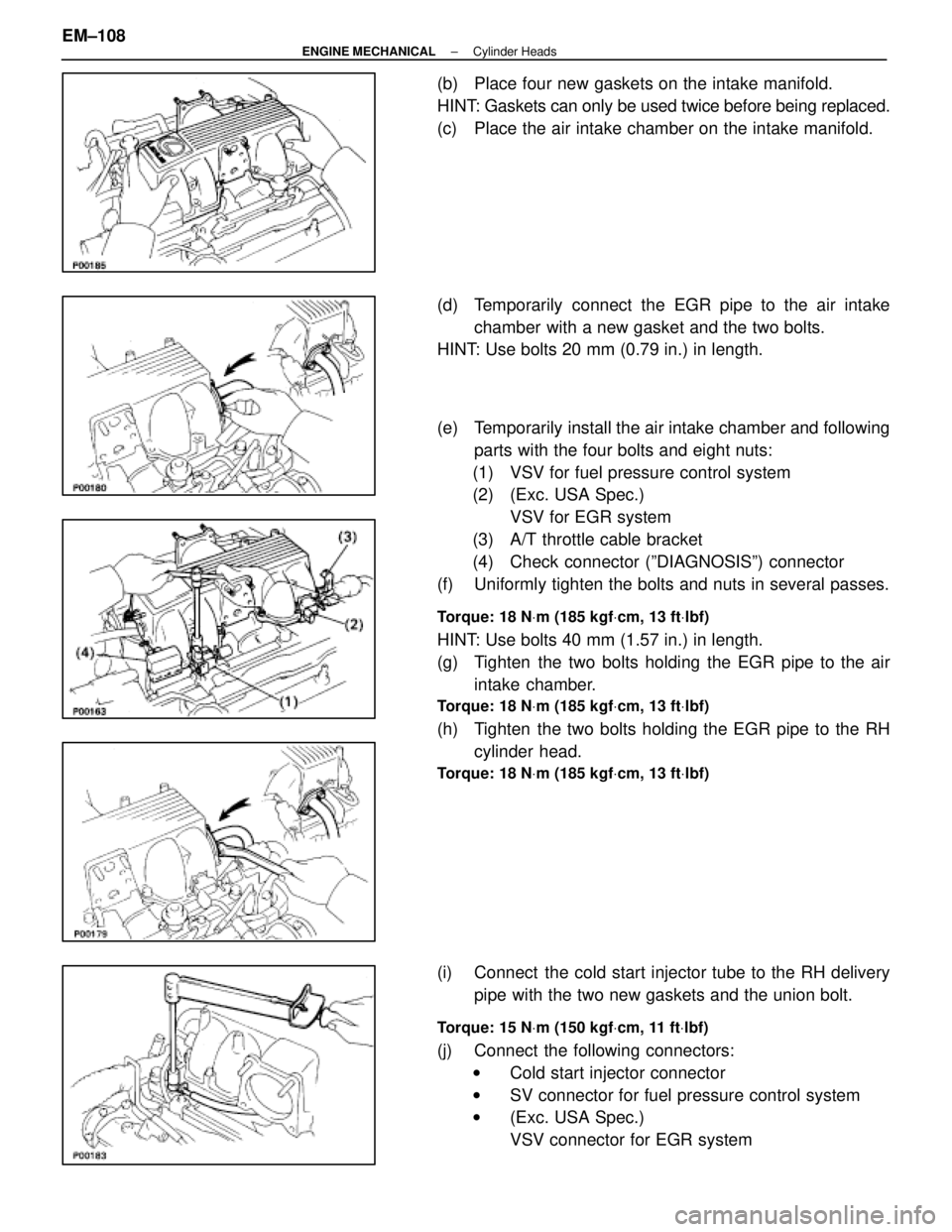
(b) Place four new gaskets on the intake manifold.
HINT: Gaskets can only be used twice before being replaced.
(c) Place the air intake chamber on the intake manifold.
(d) Temporarily connect the EGR pipe to the air intakechamber with a new gasket and the two bolts.
HINT: Use bolts 20 mm (0.79 in.) in length.
(e) Temporarily install the air intake chamber and following
parts with the four bolts and eight nuts:
(1) VSV for fuel pressure control system
(2) (Exc. USA Spec.) VSV for EGR system
(3) A/T throttle cable bracket
(4) Check connector (ºDIAGNOSISº) connector
(f) Uniformly tighten the bolts and nuts in several passes.
Torque: 18 N Vm (185 kgf Vcm, 13 ft Vlbf)
HINT: Use bolts 40 mm (1.57 in.) in length.
(g) Tighten the two bolts holding the EGR pipe to the air
intake chamber.
Torque: 18 N Vm (185 kgf Vcm, 13 ft Vlbf)
(h) Tighten the two bolts holding the EGR pipe to the RH
cylinder head.
Torque: 18 N Vm (185 kgf Vcm, 13 ft Vlbf)
(i) Connect the cold start injector tube to the RH delivery
pipe with the two new gaskets and the union bolt.
Torque: 15 N Vm (150 kgf Vcm, 11 ft Vlbf)
(j) Connect the following connectors:
w Cold start injector connector
w SV connector for fuel pressure control system
w (Exc. USA Spec.)
VSV connector for EGR system
EM±108
±
ENGINE MECHANICAL Cylinder Heads
WhereEverybodyKnowsYourName
Page 2309 of 4087

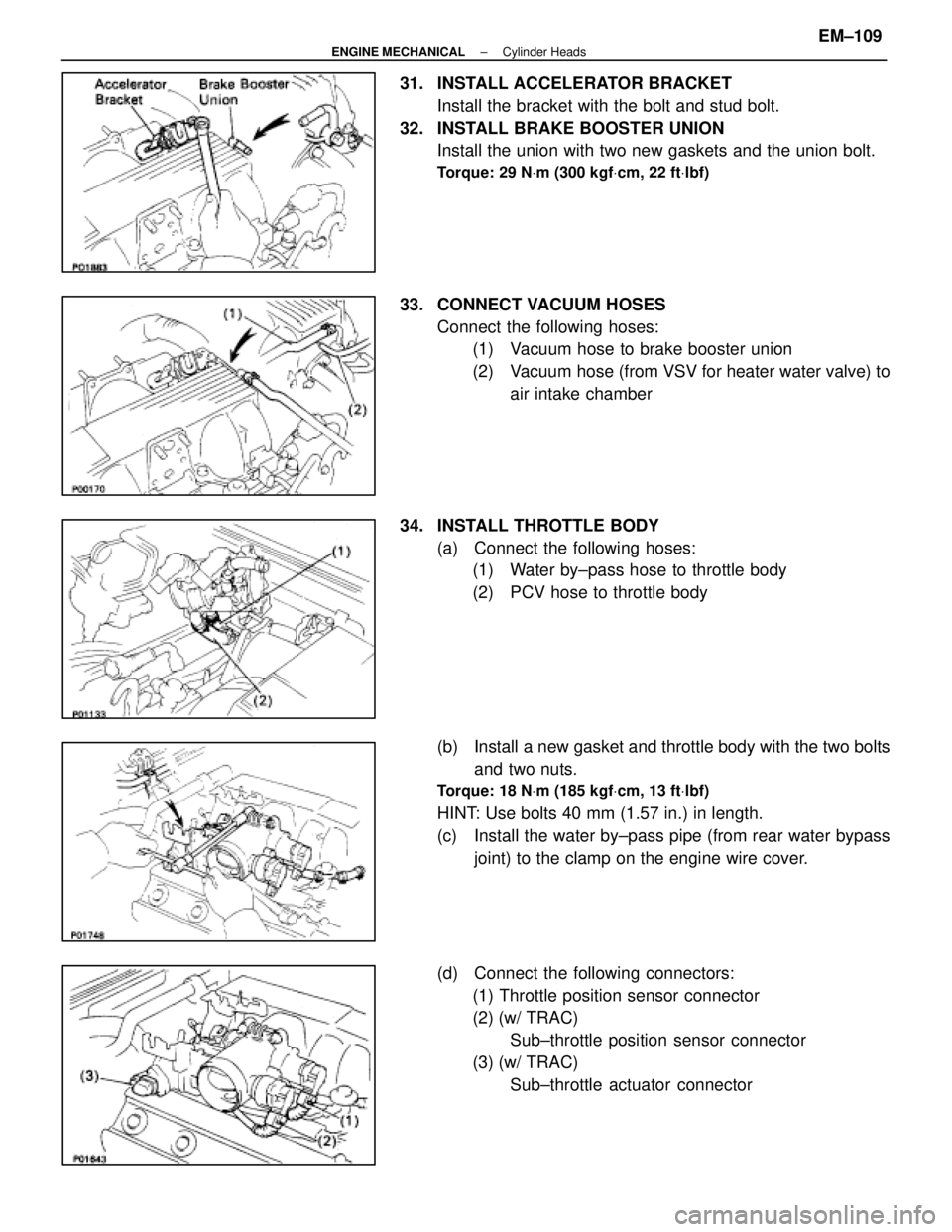
31. INSTALL ACCELERATOR BRACKETInstall the bracket with the bolt and stud bolt.
32. INSTALL BRAKE BOOSTER UNION Install the union with two new gaskets and the union bolt.
Torque: 29 N Vm (300 kgf Vcm, 22 ft Vlbf)
33. CONNECT VACUUM HOSES
Connect the following hoses:(1) Vacuum hose to brake booster union
(2) Vacuum hose (from VSV for heater water valve) to
air intake chamber
34. INSTALL THROTTLE BODY (a) Connect the following hoses:(1) Water by±pass hose to throttle body
(2) PCV hose to throttle body
(b) Install a new gasket and throttle body with the two bolts and two nuts.
Torque: 18 N Vm (185 kgf Vcm, 13 ft Vlbf)
HINT: Use bolts 40 mm (1.57 in.) in length.
(c) Install the water by±pass pipe (from rear water bypass
joint) to the clamp on the engine wire cover.
(d) Connect the following connectors: (1) Throttle position sensor connector
(2) (w/ TRAC) Sub±throttle position sensor connector
(3) (w/ TRAC) Sub±throttle actuator connector
±
ENGINE MECHANICAL Cylinder HeadsEM±109
WhereEverybodyKnowsYourName
Page 2310 of 4087
35. INSTALL HEATER WATER VALVE(a) Install the water valve and bracket assembly with thetwo bolts.
(b) Install the engine wire clamp with the bolt.
(c) Connect the VSV connector.
36. INSTALL ISC VALVE (a) Install a new gasket and the ISC valve with the two nuts.
Torque: 18 N Vm (185 kgf Vcm, 13 ft Vlbf)
(b) Connect the water by±pass hose (from throttle body) to
the ISC valve.
(c) Connect the ISC valve connector.
37. INSTALL EGR VALVE ADAPTOR (a) Install a new gasket, the adaptor and connector bracket(USA spec. only) with the two bolts and two nuts.
Torque: 18 N Vm (185 kgf Vcm, 13 ft Vlbf)
HINT: Use bolts 20 mm (1.79 in.) in length.
NOTICE: Do not touch the air intake chamber and adap-
tor surfaces of the gasket with your hand.
(b) Connect the PCV hose to cylinder head.
(c) (USA Spec. only)
Connect the EGR gas temperature sensor connector.
EM±110
±
ENGINE MECHANICAL Cylinder Heads
WhereEverybodyKnowsYourName
Page 2312 of 4087
(c) Connect the following hoses:(1) Water by±pass pipe hose to ISC valve
(2) Water by±pass pipe hose to water by±pass pipe (from rear water by±pass joint)
(3) Two vacuum hoses to VSV for EGR system
40. INSTALL VACUUM PIPE (a) Install the vacuum pipe, vacuum hoses assembly andEGR water by±pass pipe (USA spec. only) with the two
bolts.
(b) Connect the following hoses: (1) (USA Spec.) Vacuum hose to throttle body
(2) (Exc. USA Spec.) Three vacuum hoses to throttle body
(3) Vacuum hose to fuel pressure regulator
(4) Two vacuum hoses to VSV for fuel pressure control system
(5) (Exc. USA Spec.) Two vacuum hoses to EGR vacuum modulator
(6) Two vacuum hoses (from VSV for EVAP system) to vacuum pipe
(7) Vacuum hose (from VSV for fuel pressure control system) to air intake chamber
(8) Vacuum hose (from charcoal canister) to vacuum pipe
EM±112
±
ENGINE MECHANICAL Cylinder Heads
WhereEverybodyKnowsYourName
Page 2322 of 4087
15. DISCONNECT ENGINE WIRE CONNECTORS
16. DISCONNECT THEFT DETERRENT HORN CONNECTOR
17. DISCONNECT GROUND CABLE FROM BODY
18. DISCONNECT PS SOLENOID VALVE CONNECTOR
19. DISCONNECT WIRE CLAMP (FOR ALTERNATOR) FROMVSV (FOR EVAP SYSTEM)
(a) Remove the two bolts, and disconnect the VSV from the
RH cylinder head.
(b) Disconnect the wire clamp from the VSV bracket.
20. REMOVE ALTERNATOR (a) Disconnect the alternator connector.
(b) Remove the cap and nut, and disconnect the alternatorwire.
(c) Remove the mounting bolt and nut.
(d) Disconnect the A/T oil cooler pipe bracket.
(e) Remove the alternator.
21. D I S C O N N E C T P S T U B E S F R O M S U SPENSION
CROSSMEMBER
Remove the clamp bolt, and disconnect the PS tubes.
EM±122
±
ENGINE MECHANICAL Cylinder Block
WhereEverybodyKnowsYourName
Page 2323 of 4087

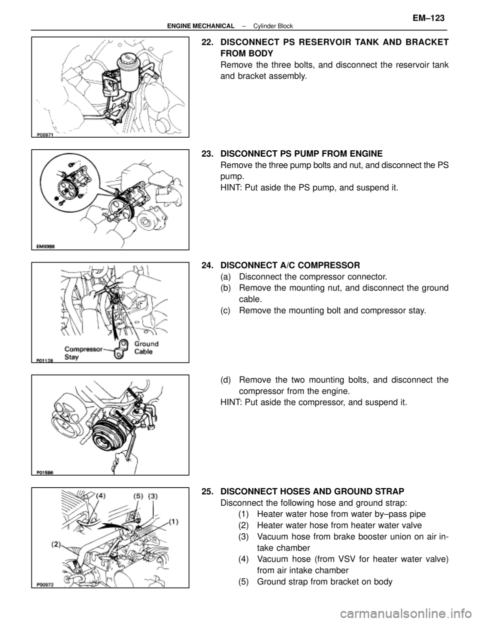
22. DISCONNECT PS RESERVOIR TANK AND BRACKET
FROM BODY
Remove the three bolts, and disconnect the reservoir tank
and bracket assembly.
23. DISCONNECT PS PUMP FROM ENGINE Remove the three pump bolts and nut, and disconnect the PS
pump.
HINT: Put aside the PS pump, and suspend it.
24. DISCONNECT A/C COMPRESSOR (a) Disconnect the compressor connector.
(b) Remove the mounting nut, and disconnect the groundcable.
(c) Remove the mounting bolt and compressor stay.
(d) Remove the two mounting bolts, and disconnect the compressor from the engine.
HINT: Put aside the compressor, and suspend it.
25. DISCONNECT HOSES AND GROUND STRAP Disconnect the following hose and ground strap:(1) Heater water hose from water by±pass pipe
(2) Heater water hose from heater water valve
(3) Vacuum hose from brake booster union on air in-
take chamber
(4) Vacuum hose (from VSV for heater water valve)
from air intake chamber
(5) Ground strap from bracket on body
±
ENGINE MECHANICAL Cylinder BlockEM±123
WhereEverybodyKnowsYourName
Page 2371 of 4087
(g) Install the scuff plate.
(h) Connect the connectors.
(i) Install the lower instrument panel finish panel and glovecompartment door assembly with the four screws.
(j) Install the instrument panel under cover with the two clips.
12. INSTALL CHARCOAL CANISTER (a) Install the charcoal canister.
(b) Connect the vacuum hose and air hose to the charcoalcanister.
13. CONNECT HOSES Connect the following hose and ground strap:(1) Heater water hose to water by±pass pipe
(2) Heater water hose to heater water valve
(3) Vacuum hose to brake booster union on air intake
chamber
(4) Vacuum hose (from VSV for heater water valve) to
air intake chamber
(5) Ground strap to bracket on body
±
ENGINE MECHANICAL Cylinder BlockEM±171
WhereEverybodyKnowsYourName
Page 2373 of 4087
17. INSTALL PS TUBESInstall the PS tube clamp with the bolt.
18. INSTALL ALTERNATOR (a) Install the alternator and A/T oil cooler pipe bracket withthe bolt and nut.
Torque: 37 N Vm (380 kgf Vcm, 27 ft Vlbf)
(b) Connect the alternator connector.
(c) Connect the alternator wire with the nut and cap.
19. INSTALL WIRE CLAMP (FOR ALTERNATOR) AND VSV (FOR EVAP SYSTEM)
(a) Install the wire clamp to the VSV bracket.
(b) Install the VSV with the two bolts.
20. CONNECT PS SOLENOID VALVE CONNECTOR
21. CONNECT ENGINE WIRE CONNECTORS
22. CONNECT THEFT DETERRENT HORN CONNECTOR
23. INSTALL GROUND CABLE TO BODY
±
ENGINE MECHANICAL Cylinder BlockEM±173
WhereEverybodyKnowsYourName