Page 2474 of 4087
(b) (Exc. USA Spec.)Install the water by±pass pipe to the VSV with the bolt.
(c) Connect the following hoses to VSV: (1) Vacuum hose (from fuel pressure regulator)
(2) Vacuum hose (from air intake chamber)
(d) Connect the VSV connector.
5. RECONNECT CABLE TO NEGATIVE TERMINAL OF BATTERY
FI±94
EFI SYSTEM
± Electronic Control System (VSV for Fuel Pressure Control)
WhereEverybodyKnowsYourName
Page 2475 of 4087
VSV for EVAP
INSPECTION OF VSV FOR EVAP
(See Emission Control System on page EC±11) FI±95
± Electronic Control System (VSV f\
or EVAP)EFI SYSTEM
WhereEverybodyKnowsYourName
Page 2476 of 4087
VSV for EGR (Exc. USA Spec.)
INSPECTION OF VSV FOR EGR
(See Emission Control Systems on page EC±18)
FI±96
± Electronic Control Syst\
em (VSV for EGR (Exc. USA Spec.))EFI SYSTEM
WhereEverybodyKnowsYourName
Page 2477 of 4087
EGR Valve (USA Spec. only)
INSPECTION OF VSV FOR EGR
(See Emission Control Systems on page EC±21) FI±97
± Electronic Control System (E\
GR Valve (USA Spec. Only))EFI SYSTEM
WhereEverybodyKnowsYourName
Page 2507 of 4087

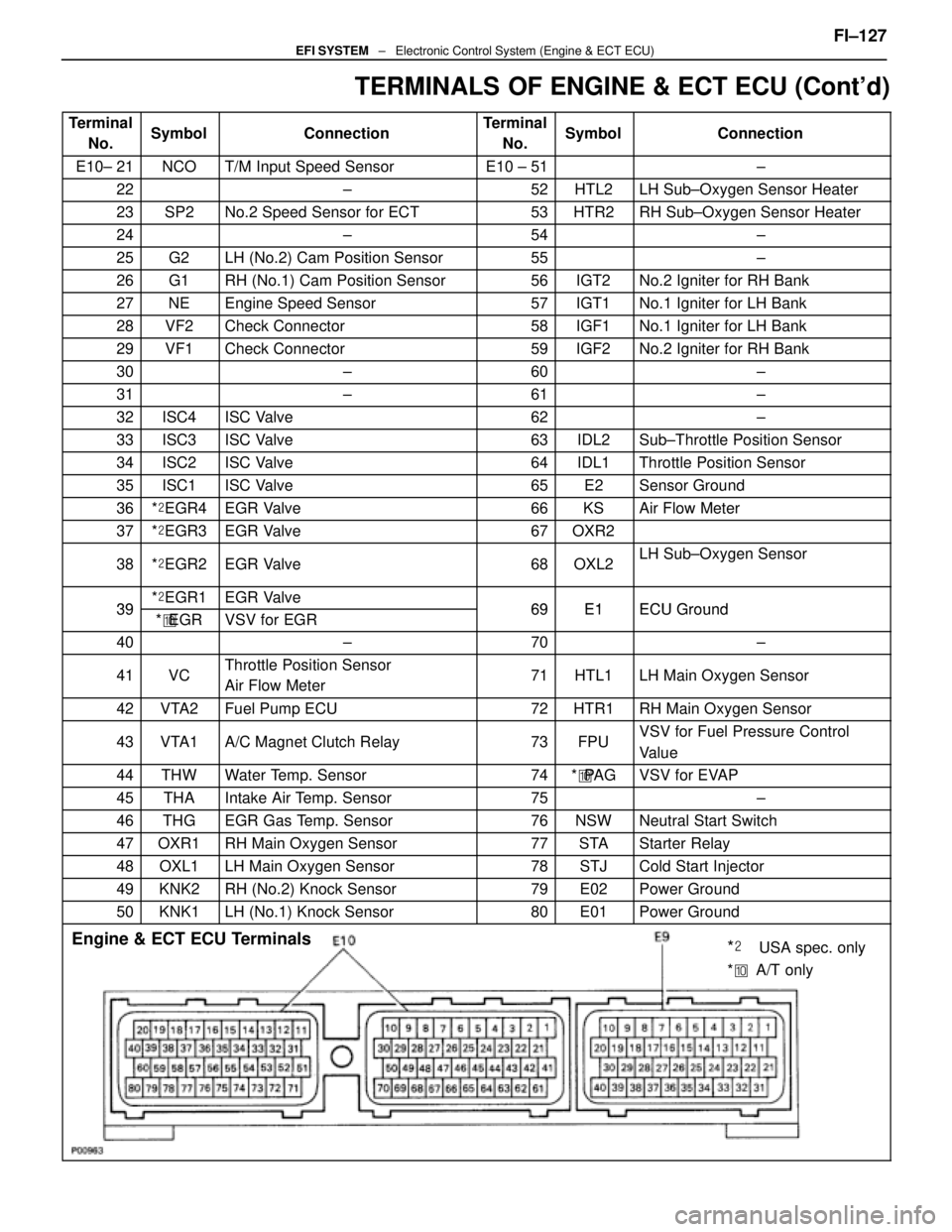
TERMINALS OF ENGINE & ECT ECU (Cont'd)
TerminalNo.SymbolConnectionTerminalNo.SymbolConnection
E10± 21NCOT/M Input Speed SensorE10 ± 51±
22±52HTL2LH Sub±Oxygen Sensor Heater
23SP2No.2 Speed Sensor for ECT53HTR2RH Sub±Oxygen Sensor Heater
24±54±
25G2LH (No.2) Cam Position Sensor55±
26G1RH (No.1) Cam Position Sensor56IGT2No.2 Igniter for RH Bank
27NEEngine Speed Sensor57IGT1No.1 Igniter for LH Bank
28VF2Check Connector58IGF1No.1 Igniter for LH Bank
29VF1Check Connector59IGF2No.2 Igniter for RH Bank
30±60±
31±61±
32ISC4ISC Valve62±
33ISC3ISC Valve63IDL2Sub±Throttle Position Sensor
34ISC2ISC Valve64IDL1Throttle Position Sensor
35ISC1ISC Valve65E2Sensor Ground
36*� EGR4EGR Valve66KSAir Flow Meter
37*� EGR3EGR Valve67OXR2
38*� EGR2EGR Valve68OXL2LH Sub±Oxygen Sensor
39*� EGR1EGR Valve69E1ECU Ground39*� EGRVSV for EGR69E1ECU Ground
40±70±
41VCThrottle Position Sensor
Air Flow Meter71HTL1LH Main Oxygen Sensor
42VTA2Fuel Pump ECU72HTR1RH Main Oxygen Sensor
43VTA1A/C Magnet Clutch Relay73FPUVSV for Fuel Pressure Control
Value
44THWWater Temp. Sensor74*� PA GVSV for EVAP
45THAIntake Air Temp. Sensor75±
46THGEGR Gas Temp. Sensor76NSWNeutral Start Switch
47OXR1RH Main Oxygen Sensor77STAStarter Relay
48OXL1LH Main Oxygen Sensor78STJCold Start Injector
49KNK2RH (No.2) Knock Sensor79E02Power Ground
50KNK1LH (No.1) Knock Sensor80E01Power Ground
Engine & ECT ECU Terminals
*��USA spec. only
* �� A/T only
FI±127EFI SYSTEM ± Electronic Control System (Engine & ECT ECU)
WhereEverybodyKnowsYourName
Page 2517 of 4087

SERVICE SPECIFICATIONS
SERVICE DATA
Fuel pumpResistance0.2 ± 3.0 �
Cold start
injectorResistance
Fuel leakage2 ± 4 �
One drop or less per minute
Fuel pressure
regulatorFuel pressureat no vacuum265 ± 304 kPa
(2.7 ± 3.1 kgf/cm2, 38 ± 44 psi)
InjectorResistance
Injection volume
Difference between each cylinder
Fuel leakage13.4 ± 14.2 �
55 ± 70 cc (3.4 ± 4.3 cu in.) per 15 sec.
10 cc (0.6 cu in.) or less
One drop or less per minute
Air flow meterResistance (THA ± E2)at±20 °C (±4 °F)
at 0 °C (32 °F)
at 20 °C (68 °F)
at 40 °C (104 °F)
at 60 °C (140 °F)
at 80 °C (176 °F)10 ± 20 k �
4 ± 7 k �
2 ± 7 k �
0.9 ± 1.3 k �
0.4 ± 0.7 k �
0.2 ± 0.4 k �
Throttle bodyThrottle body fully closed angle6°
Throttle
positionClearance between
stop screw and leverBetween terminalsResistance
sensor
(main)0 mm
0.40 mm
0.65 mm0 in.
0.016 in.
0.026 in.VTA1 ± E2 IDL1 ± E2
IDL1 ± E2
VTA1 E2
0.2 ± 0.8 k �
2.3 k � or less
Infinity
33 100k �Throttle valve fully opened position
±VTA1 ± E2VC ± E2
y
3.3 ± 10.0 k �
4.0 ± 9.0 k �
Sub±throttle
positionClearance between
stop screw and leverBetween terminalsResistance
sensor
(w/ TRAC)0 mm
0.30 mm
0.50 mm0 in.
0.012 in.
0.020 in.VTA2 ± E2 IDL2 ± E2
IDL2 ± E2
VTA2 E2
0.2 ± 0.8 k �
2.3 k � or less
Infinity
33 100k �Throttle valve fully opened position
±VTA2 ± E2VC ± E2
y
3.3 ± 10.0 k �
4.0 ± 9.0 k �
Sub±throttle
actuator
(w/ TRAC)Resistance (ACM ± A and A, BCM ± B and B)0.5 ± 1.0 �
ISC valveResistance (B1 ± S1 and S3, B2 ± S2 and S4)10 ± 30 �
Cold start
injector time
switchResistance STA ± STJ below 15 °C (59 °F)
above 30 °C (86 °F)
STA ± Ground25 ± 45 �
65 ± 85
25 ± 85 �
VSV for fuel
pressure
controlResistance37 ± 44 �
FI±137 ± Service SpecificationsEFI SYSTEM
WhereEverybodyKnowsYourName
Page 2535 of 4087
6. REMOVE VSV FOR EVAP SYSTEMRemove the two bolts, and disconnect the VSV from cylinder
head and timing belt cover.
7. REMOVE RH NO.3 TIMING BELT COVER Remove the three bolts and timing belt cover.
8. REMOVE LH NO.3 TIMING BELT COVER (a) Remove the four mounting bolts.
(b) Disconnect the cord grommet from the timing belt cover,
and remove the timing belt cover.
(c) Remove the cord grommet from the high±tension cord.
9. REMOVE HIGH±TENSION CORDS (a) Disconnect the high±tension cords from the spark plugs
and distributor caps. Disconnect the high±tension cords
at the rubber boot. Do not pull on the cords.
NOTICE: Pulling on or bending the cords may damage
the conductor inside.
±
IGNITION SYSTEM High±Tension Cords and Cord ClampsIG±13
WhereEverybodyKnowsYourName
Page 2540 of 4087

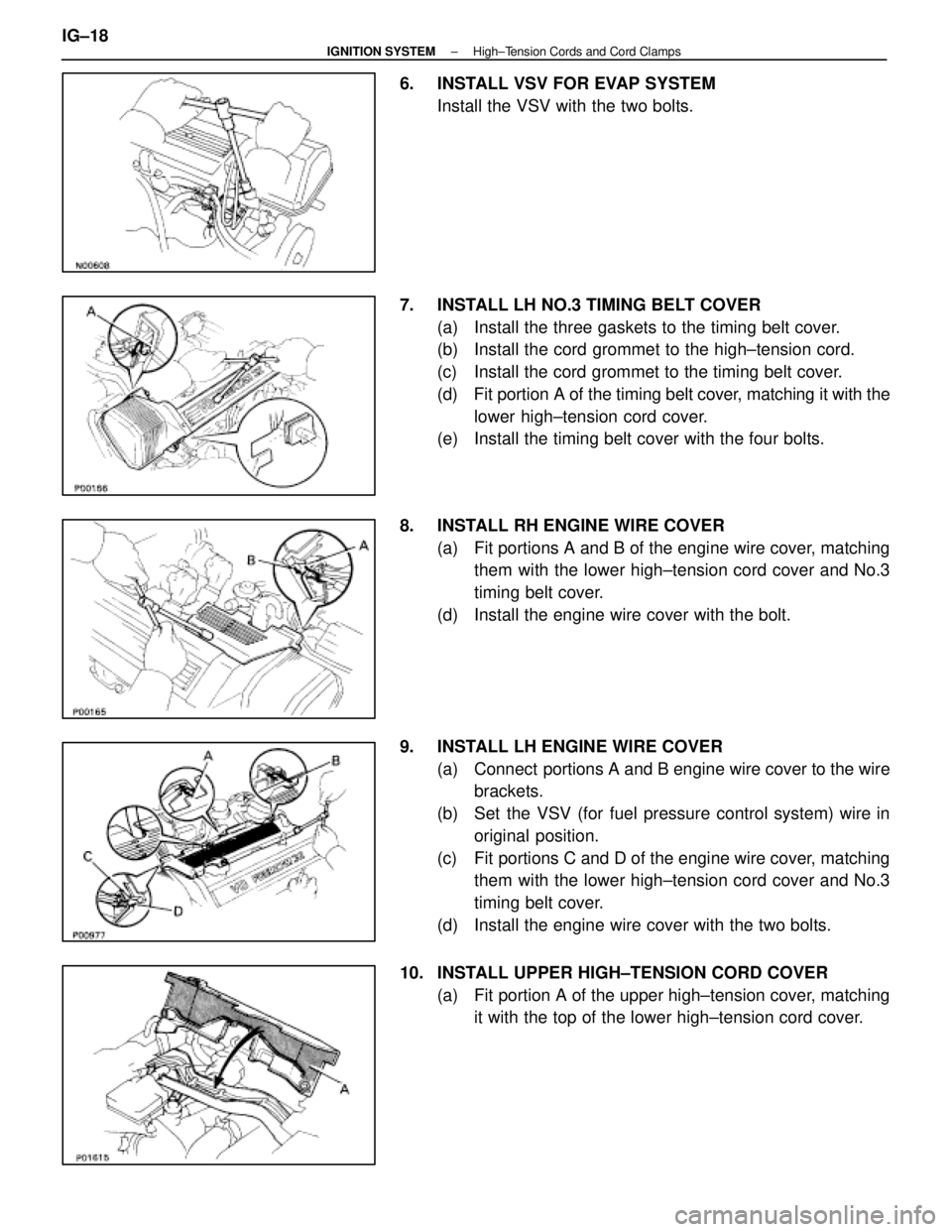
6. INSTALL VSV FOR EVAP SYSTEMInstall the VSV with the two bolts.
7. INSTALL LH NO.3 TIMING BELT COVER (a) Install the three gaskets to the timing belt cover.
(b) Install the cord grommet to the high±tension cord.
(c) Install the cord grommet to the timing belt cover.
(d) Fit portion A of the timing belt cover, matching it with the
lower high±tension cord cover.
(e) Install the timing belt cover with the four bolts.
8. INSTALL RH ENGINE WIRE COVER (a) Fit portions A and B of the engine wire cover, matchingthem with the lower high±tension cord cover and No.3
timing belt cover.
(d) Install the engine wire cover with the bolt.
9. INSTALL LH ENGINE WIRE COVER (a) Connect portions A and B engine wire cover to the wirebrackets.
(b) Set the VSV (for fuel pressure control system) wire in original position.
(c) Fit portions C and D of the engine wire cover, matching them with the lower high±tension cord cover and No.3
timing belt cover.
(d) Install the engine wire cover with the two bolts.
10. INSTALL UPPER HIGH±TENSION CORD COVER (a) Fit portion A of the upper high±tension cover, matchingit with the top of the lower high±tension cord cover.
IG±18
±
IGNITION SYSTEM High±Tension Cords and Cord Clamps
WhereEverybodyKnowsYourName