Page 2881 of 4087
SERVICE SPECIFICATIONS
SERVICE DATA
VSVResistance30±34 �
for EVAP
VSVResistance33±39 �
for EGR
EGR valveResistance19.9±23.4 �
(CALIF. only)
TORQUE SPECIFICATIONS
Part tightenedNVmkgf Vcmft Vlbf
VSV for EGR X Air intake chamber (Exc. USA Spec.)1818513
EGR valve X Air intake chamber18185 13
Catalytic converter (Main) X Exhaust manifold62630 46
Catalytic converter (Main) X Front exhaust pipe43440 32
Front exhaust pipe support bracket X Transmission43440 32
Front exhaust pipe X Center exhaust pipe43440 32
Main oxygen sensor X Front exhaust pipe4445033
EC±30±
EMISSION CONTROL SYSTEMS Servuce Specifications
WhereEverybodyKnowsYourName
Page 2897 of 4087
6. REMOVE UPPER HIGH±TENSION CORD COVER(a) Remove the two mounting bolts.
(b) Disconnect the front side claw groove of the cord coverfrom the claw of the lower cover, and remove the cord
cover.
7. REMOVE RH ENGINE WIRE COVER Remove the bolt and engine wire cover.
8. REMOVE LH ENGINE WIRE COVER Remove the two bolts and engine wire cover.
9. REMOVE VSV FOR EVAP SYSTEM Remove the two bolts, and disconnect the VSV from cylinder
head and timing belt cover.
10. REMOVE RH NO.3 TIMING BELT COVER Remove the three bolts and timing belt cover.
±
STARTING SYSTEM StarterST±7
WhereEverybodyKnowsYourName
Page 2899 of 4087
(2) Water by±pass hose from ISC valve
(3) (USA Spec.)Vacuum hose from throttle body
(4) (Exc. USA Spec.)
Three vacuum hoses from throttle body
(c) Remove the two bolts and two nuts, disconnect the throttle body from the air intake chamber.
(d) Disconnect the following hoses, and remove the throttle body:
(1) PCV hose from throttle body
(2) Water by±pass hose from throttle body
(e) Remove the throttle body gasket.
14. DISCONNECT CONNECTORS Disconnect the following connectors:
wCold start injector connector
w ISC valve connector
w (USA Spec.)
EGR Valve connector
w (Exc. USA Spec.)
VSV connector for EGR system
w VSV connector for fuel pressure control system
±
STARTING SYSTEM StarterST±9
WhereEverybodyKnowsYourName
Page 2900 of 4087
15. DISCONNECT HOSESDisconnect the following hoses:(1) Water by±pass hose (from water inlet housing) from ISC valve
(2) Vacuum hose (from PS air control valve) from air in-
take chamber
(3) Vacuum sensing hose (from fuel pressure regula- tor) from vacuum pipe
(4) Two vacuum hoses (from VSV for EVAP system) from vacuum pipe
(5) Vacuum hose (from charcoal canister) from vacu- um pipe.
(6) Water by±pass hose (from EGR valve) from water by±pass pipe
(7) Vacuum hose (from brake booster) from air intake chamber
(8) Vacuum hose (from VSV for heater water valve)
from air intake chamber
(9) PCV hose from LH cylinder head cover
16. REMOVE AIR INTAKE CHAMBER (a) Remove the bolt, stud bolt and accelerator bracket.
ST±10
±
STARTING SYSTEM Starter
WhereEverybodyKnowsYourName
Page 2918 of 4087
12. INSTALL AIR INTAKE CHAMBER(a) Place four new gaskets and the air intake chamber onthe intake manifold.
(b) Temporarily install a new gasket and the EGR pipe to air
intake chamber with the two bolts.
(c) (Exc. USA Spec.) Install the connector bracket to check (ºDIAGNOSISº)
connector.
(d) Install the air intake chamber and following parts with the four bolts and eight nuts:
(1) Check (ºDIAGNOSISº) connector
(2) A/T throttle cable bracket
(3) VSV for fuel pressure control system
(4) VSV for EGR system
Torque: 18 N Vm (185 kgf Vcm, 13 ft Vlbf)
HINT: Use bolts 40 mm (1.57 in.) of length.
ST±28
±
STARTING SYSTEM Starter
WhereEverybodyKnowsYourName
Page 2919 of 4087
(e) Tighten the bolt holding the EGR pipe to the air intakechamber.
Torque: 18 N Vm (185 kgf Vcm, 13 ft Vlbf)
(f) Tighten the bolt holding the EGR pipe to the RH cylinder
head.
Torque: 18 N Vm (185 kgf Vcm, 13 ft Vlbf)
(g) Connect the cold start injector tube to the RH delivery
pipe with two new gaskets and union bolt.
Torque: 15 N Vm (150 kgf Vcm, 11 ft Vlbf)
(h) Install the accelerator bracket with the bolt and stud bolt.
13. CONNECT HOSES Connect the following hoses:(1) Water by±pass (from EGR valve) to water bypass
pipe
(2) Vacuum hose (from brake booster) to air intake chamber
(3) Vacuum hose (from VSV for heater water valve) to
air intake chamber
(4) PCV hose to LH cylinder head cover
±
STARTING SYSTEM StarterST±29
WhereEverybodyKnowsYourName
Page 2920 of 4087

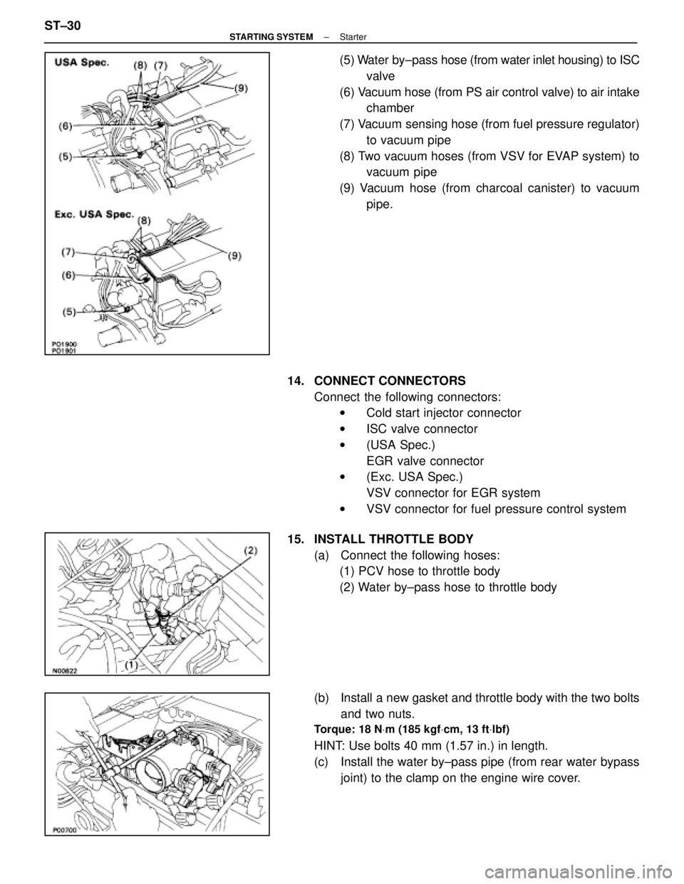
(5) Water by±pass hose (from water inlet housing) to ISC
valve
(6) Vacuum hose (from PS air control valve) to air intake chamber
(7) Vacuum sensing hose (from fuel pressure regulator) to vacuum pipe
(8) Two vacuum hoses (from VSV for EVAP system) to vacuum pipe
(9) Vacuum hose (from charcoal canister) to vacuum pipe.
14. CONNECT CONNECTORS Connect the following connectors:w Cold start injector connector
w ISC valve connector
w (USA Spec.)
EGR valve connector
w (Exc. USA Spec.)
VSV connector for EGR system
w VSV connector for fuel pressure control system
15. INSTALL THROTTLE BODY (a) Connect the following hoses:(1) PCV hose to throttle body
(2) Water by±pass hose to throttle body
(b) Install a new gasket and throttle body with the two bolts and two nuts.
Torque: 18 N Vm (185 kgf Vcm, 13 ft Vlbf)
HINT: Use bolts 40 mm (1.57 in.) in length.
(c) Install the water by±pass pipe (from rear water bypass
joint) to the clamp on the engine wire cover.
ST±30
±
STARTING SYSTEM Starter
WhereEverybodyKnowsYourName
Page 2922 of 4087

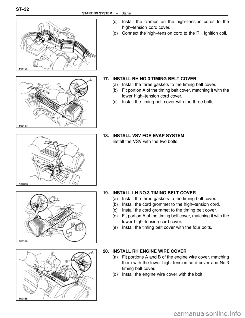
(c) Install the clamps on the high±tension cords to thehigh±tension cord cover.
(d) Connect the high±tension cord to the RH ignition coil.
17. INSTALL RH NO.3 TIMING BELT COVER (a) Install the three gaskets to the timing belt cover.
(b) Fit portion A of the timing belt cover, matching it with the
lower high±tension cord cover.
(c) Install the timing belt cover with the three bolts.
18. INSTALL VSV FOR EVAP SYSTEM Install the VSV with the two bolts.
19. INSTALL LH NO.3 TIMING BELT COVER (a) Install the three gaskets to the timing belt cover.
(b) Install the cord grommet to the high±tension cord.
(c) Install the cord grommet to the timing belt cover.
(d) Fit portion A of the timing belt cover, matching it with the
lower high±tension cord cover.
(e) Install the timing belt cover with the four bolts.
20. INSTALL RH ENGINE WIRE COVER (a) Fit portions A and B of the engine wire cover, matchingthem with the lower high±tension cord cover and No.3
timing belt cover.
(d) Install the engine wire cover with the bolt.
ST±32
±
STARTING SYSTEM Starter
WhereEverybodyKnowsYourName