Page 2923 of 4087

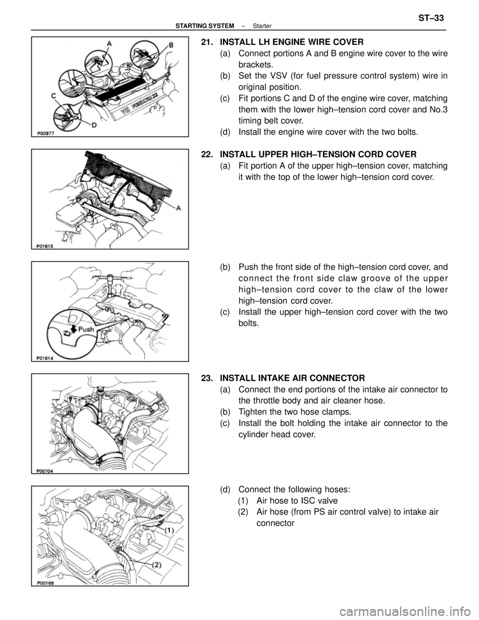
21. INSTALL LH ENGINE WIRE COVER(a) Connect portions A and B engine wire cover to the wirebrackets.
(b) Set the VSV (for fuel pressure control system) wire in
original position.
(c) Fit portions C and D of the engine wire cover, matching them with the lower high±tension cord cover and No.3
timing belt cover.
(d) Install the engine wire cover with the two bolts.
22. INSTALL UPPER HIGH±TENSION CORD COVER (a) Fit portion A of the upper high±tension cover, matchingit with the top of the lower high±tension cord cover.
(b) Push the front side of the high±tension cord cover, and connect the front side claw groove of the upper
high±tension cord cover to the claw of the lower
high±tension cord cover.
(c) Install the upper high±tension cord cover with the two
bolts.
23. INSTALL INTAKE AIR CONNECTOR (a) Connect the end portions of the intake air connector tothe throttle body and air cleaner hose.
(b) Tighten the two hose clamps.
(c) Install the bolt holding the intake air connector to the cylinder head cover.
(d) Connect the following hoses: (1) Air hose to ISC valve
(2) Air hose (from PS air control valve) to intake air connector
±
STARTING SYSTEM StarterST±33
WhereEverybodyKnowsYourName
Page 3368 of 4087
Fuel Pressure Control VSV Circuit
CIRCUIT DESCRIPTION
The ECU turns on a VSV (Vacuum Switching Valve)
to draw the air into the diaphragm chamber of the
pressure regulator if it detects that the temperature of
the coolant is too high during engine starting.
The air drawn into the chamber increases the fuel
pressure to prevent fuel vapor lock at high engine
temperature in order to help the engine start when it
is warm.
Fuel pressure control ends approx. 100 secs. after
the engine is started.
DIAGNOSTIC CHARTDIAGNOSTIC CHART
Check operation for fuel pressure control
VSV.Replace fuel pressure control VSV.
Repair or replace harness or
connector.
Proceed to next circuit inspection
shown on matrix chart (See page
TR±35).
Check for open and short in harness and
connector between main relay and ECU.
Check voltage of VSV power source.
Check and replace ECU.
WIRING DIAGRAM
TR±142±
ENGINE TROUBLESHOOTING Circuit Inspection
WhereEverybodyKnowsYourName
Page 3369 of 4087
OKNG
INSPECTION PROCEDURE
1Check fuel pressure control VSV.
C
OK
P
OK
C
(2) Remove fuel pressure control VSV.
(2) Disconnect fuel pressure control VSV connector.
(2) Measure resistance between terminals.
(2) Measure resistance between each terminal and thebody.
1. Resistance: 30 ± 50 at 20C (68F)
2. Resistance: 1M or higher
Check operation of fuel pressure control VSV when bat-
tery voltage is applied to the terminals of fuel pressure
control VSV connector or not.
Battery voltage is applied:
The air from pipe E is flowing out through the air fil-
ter.
Battery voltage is not applied:
The air from pipe E is flowing out through pipe G.
Replace fuel pressure control VSV.
Go to step 2.
±
ENGINE TROUBLESHOOTING Circuit InspectionTR±143
WhereEverybodyKnowsYourName
Page 3370 of 4087
NGOK
OKNG
2Check voltage between terminal FPU of engine & ECT ECU connector and body gro\
und.
C
OK
Hint
P(2) Connect the Check Harness A.(See page TR±30)
(2) Turn ignition switch on.
Measure voltage between terminal FPU of engine &
ECT ECU connector and body ground.
Voltage: 10 ± 14 V
Proceed to next circuit inspection shown on matrix chart
(See page TR±35).
3
Check for open and short in harness and connector between engine & ECT ECU an\
d VSV, VSV
and EFI main relay (See page IN±27).
Repair or replace harness or connector
Check and replace engine & ECT ECU.
TR±144±
ENGINE TROUBLESHOOTING Circuit Inspection
WhereEverybodyKnowsYourName
Page 3524 of 4087

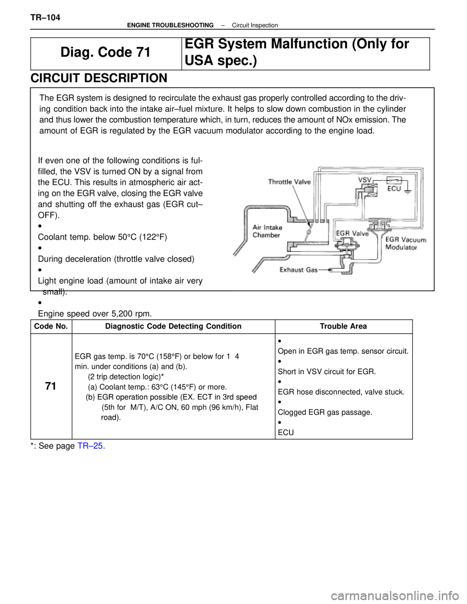
Diag. Code 71
EGR System Malfunction (Only for
USA spec.)
CIRCUIT DESCRIPTION
If even one of the following conditions is ful-
filled, the VSV is turned ON by a signal from
the ECU. This results in atmospheric air act-
ing on the EGR valve, closing the EGR valve
and shutting off the exhaust gas (EGR cut±
OFF).
w
Coolant temp. below 505C (122 5F)
w
During deceleration (throttle valve closed)
w
Light engine load (amount of intake air very
small).
w
Engine speed over 5,200 rpm. The EGR system is designed to recirculate the exhaust gas properly controll\
ed according to the driv-
ing condition back into the intake air±fuel mixture. It helps to slow dow\
n combustion in the cylinder
and thus lower the combustion temperature which, in turn, reduces the amoun\
t of NOx emission. The
amount of EGR is regulated by the EGR vacuum modulator according to the engine\
load.
Code No.Diagnostic Code Detecting ConditionTrouble Area
EGR t i 70
5C (158 5F) b l f 1 4
w
Open in EGR
gas temp. sensor circuit.EGR gas temp. is 70 5C (158 5F) or below for 1 4
min. under conditions (a) and (b).
(2 trip detection logic)*
Oen in EGR gas tem. sensor circuit.
w
Short in VSV circuit for EGR.
71
(2 trip detection logic)*
(a) Coolant temp.: 63 5C (145 5F) or more.
(b) EGR operationpossible (EX ECT in 3rd speed
Short in VSV circuit for EGR.
w
EGR hose disconnected, valve stuck.
(b) EGR operation possible (EX. ECT in 3rd speed
(5th for M/T), A/C ON, 60 mph (96 km/h), Flat
road)
EGR hose disconnected, valve stuck.
w
Clogged EGR gas passage.
road).gg g g
w
ECU
*: See page TR±25.
TR±104
±
ENGINE TROUBLESHOOTING Circuit Inspection
WhereEverybodyKnowsYourName
Page 3526 of 4087
DIAGNOSTIC CHART
Check voltage of VSV for EGR Power
source.
Check resistance of VSV for EGR.
Repair or replace harness or
connector.
Replace VSV for EGR.
Check for open and short in harness and
connector between EFI main relay and ECU.
Check and replace EGR.
Check EGR system (See page EC±12).
Check resistance of EGR gas temp. sensor.
Check and replace EGR.
Check for open in harness and connector
between EGR gas temp, sensor and ECU.
Repair EGR system.
Replace EGR gas temp. sensor.
Repair or replace harness or
connector.
TR±106±
ENGINE TROUBLESHOOTING Circuit Inspection
WhereEverybodyKnowsYourName
Page 3528 of 4087
NGOK
OKNG
OKNG
INSPECTION PROCEDURE
1Check voltage between terminal EGR of ECM connector and body ground.
C
OK
P1. Connect the Check Harness A. (See page TR±34).
2. Warm up engine to normal operating temperature.
Measure voltage between terminal EGR of engine (&
ECT) ECU connector and body ground.
Voltage:
Go to step �.
2Check resistance between terminals of VSV for EGR.
C
OK
PRemove VSV for EGR. (See page EC±13).
Measure resistance between terminals of VSV for EGR.
Resistance: 38.5 ± 44.5 � at 20 � C (68 � F)
Replace VSV for EGR.
3Check for open and short in harness and connector between EFI main relay and \
VSV for EGR,
VSV for EGR and engine (& ECT) ECU. (See page IN±27)
Repair or replace harness or connector.
Check and replace engine (& ECT) ECU.
TR±108±
ENGINE TROUBLESHOOTING Circuit Inspection
WhereEverybodyKnowsYourName
Page 3580 of 4087
Fuel Pressure Control VSV Circuit
CIRCUIT DESCRIPTION
The ECU turns on a VSV (Vacuum Switching Valve)
to draw the air into the diaphragm chamber of the
pressure regulator if it detects that the temperature of
the coolant is too high during engine starting.
The air drawn into the chamber increases the fuel
pressure to prevent fuel vapor lock at high engine
temperature in order to help the engine start when it
is warm.
Fuel pressure control ends approx. 100 secs. after
the engine is started.
DIAGNOSTIC CHARTDIAGNOSTIC CHART
Check operation for fuel pressure control
VSV.Replace fuel pressure control VSV.
Repair or replace harness or
connector.
Proceed to next circuit inspection
shown on matrix chart (See page
TR±35).
Check for open and short in harness and
connector between main relay and ECU.
Check voltage of VSV power source.
Check and replace ECU.
WIRING DIAGRAM
TR±142±
ENGINE TROUBLESHOOTING Circuit Inspection
WhereEverybodyKnowsYourName