Page 2753 of 4087
Fuel Pressure Control VSV Circuit
CIRCUIT DESCRIPTION
The ECU turns on a VSV (Vacuum Switching Valve)
to draw the air into the diaphragm chamber of the
pressure regulator if it detects that the temperature of
the coolant is too high during engine starting.
The air drawn into the chamber increases the fuel
pressure to prevent fuel vapor lock at high engine
temperature in order to help the engine start when it
is warm.
Fuel pressure control ends approx. 100 secs. after
the engine is started.
DIAGNOSTIC CHARTDIAGNOSTIC CHART
Check operation for fuel pressure control
VSV.Replace fuel pressure control VSV.
Repair or replace harness or
connector.
Proceed to next circuit inspection
shown on matrix chart (See page
TR±35).
Check for open and short in harness and
connector between main relay and ECU.
Check voltage of VSV power source.
Check and replace ECU.
WIRING DIAGRAM
TR±142±
ENGINE TROUBLESHOOTING Circuit Inspection
WhereEverybodyKnowsYourName
Page 2754 of 4087
OKNG
INSPECTION PROCEDURE
1Check fuel pressure control VSV.
C
OK
P
OK
C
(2) Remove fuel pressure control VSV.
(2) Disconnect fuel pressure control VSV connector.
(2) Measure resistance between terminals.
(2) Measure resistance between each terminal and thebody.
1. Resistance: 30 ± 50 at 20C (68F)
2. Resistance: 1M or higher
Check operation of fuel pressure control VSV when bat-
tery voltage is applied to the terminals of fuel pressure
control VSV connector or not.
Battery voltage is applied:
The air from pipe E is flowing out through the air fil-
ter.
Battery voltage is not applied:
The air from pipe E is flowing out through pipe G.
Replace fuel pressure control VSV.
Go to step 2.
±
ENGINE TROUBLESHOOTING Circuit InspectionTR±143
WhereEverybodyKnowsYourName
Page 2755 of 4087
NGOK
OKNG
2Check voltage between terminal FPU of engine & ECT ECU connector and body gro\
und.
C
OK
Hint
P(2) Connect the Check Harness A.(See page TR±30)
(2) Turn ignition switch on.
Measure voltage between terminal FPU of engine &
ECT ECU connector and body ground.
Voltage: 10 ± 14 V
Proceed to next circuit inspection shown on matrix chart
(See page TR±35).
3
Check for open and short in harness and connector between engine & ECT ECU an\
d VSV, VSV
and EFI main relay (See page IN±27).
Repair or replace harness or connector
Check and replace engine & ECT ECU.
TR±144±
ENGINE TROUBLESHOOTING Circuit Inspection
WhereEverybodyKnowsYourName
Page 2815 of 4087
10. REMOVE LH ENGINE WIRE COVERRemove the two bolts and engine wire cover.
11. REMOVE VSV FOR EVAP SYSTEM Remove the two bolts, and disconnect the VSV from cylinder
head and timing belt cover.
12. REMOVE RH NO.3 TIMING BELT COVER Remove the three bolts and timing belt cover.
13. REMOVE LH NO.3 TIMING BELT COVER (a) Remove the four mounting bolts.
(b) Disconnect the cord grommet from the timing belt cover,
and remove the timing belt cover.
(c) Remove the cord grommet from the high±tension cord.
14. DISCONNECT RADIATOR HOSE FROM WATER INLET
15. REMOVE DRIVE BELT IDLER PULLEY Remove the pulley bolt, cover plate and idler pulley.
±
COOLIING SYSTEM Electronically Controlled Hydraulic
Cooling Fan (Hydraulic Pump)CO±29
WhereEverybodyKnowsYourName
Page 2829 of 4087

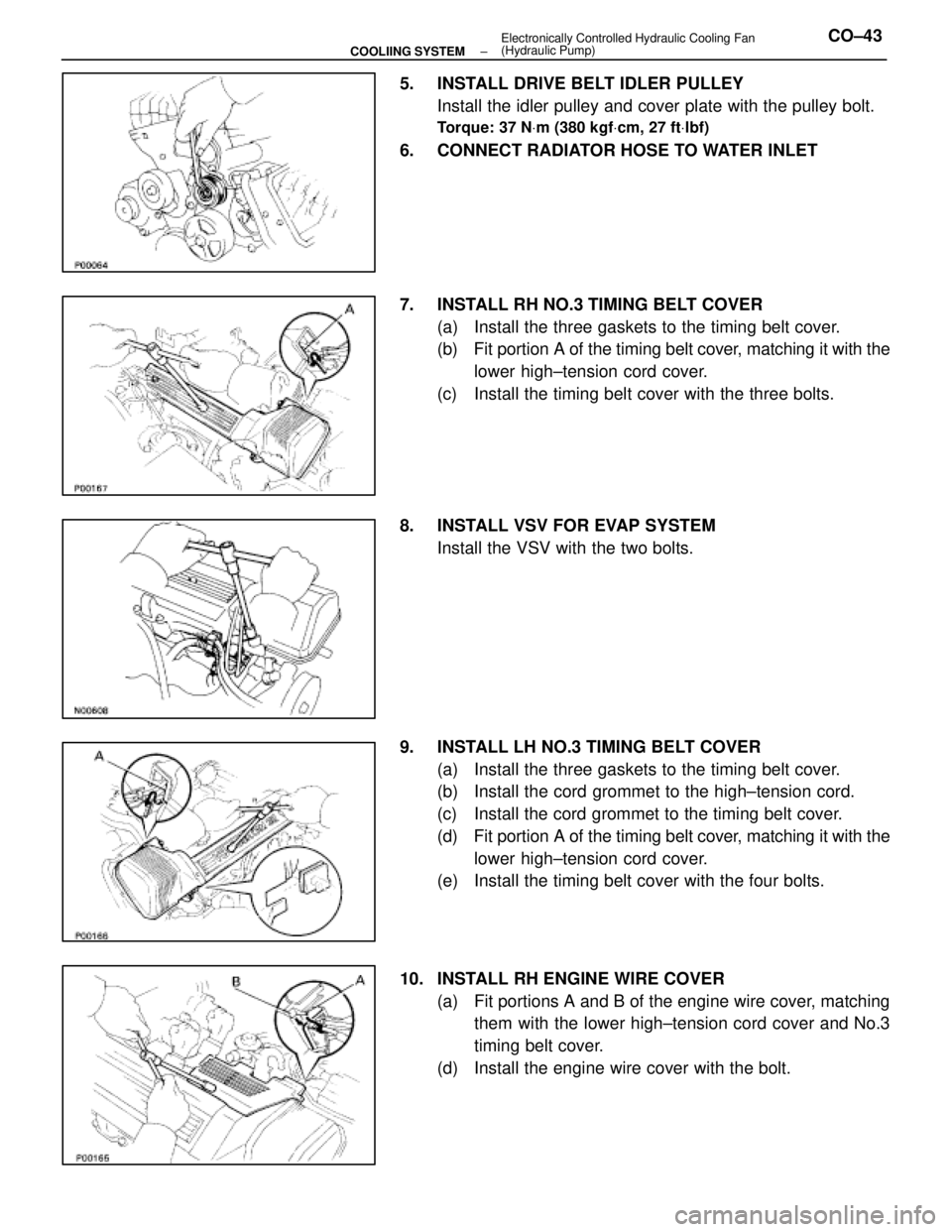
5. INSTALL DRIVE BELT IDLER PULLEYInstall the idler pulley and cover plate with the pulley bolt.
Torque: 37 N Vm (380 kgf Vcm, 27 ft Vlbf)
6. CONNECT RADIATOR HOSE TO WATER INLET
7. INSTALL RH NO.3 TIMING BELT COVER
(a) Install the three gaskets to the timing belt cover.
(b) Fit portion A of the timing belt cover, matching it with the
lower high±tension cord cover.
(c) Install the timing belt cover with the three bolts.
8. INSTALL VSV FOR EVAP SYSTEM Install the VSV with the two bolts.
9. INSTALL LH NO.3 TIMING BELT COVER (a) Install the three gaskets to the timing belt cover.
(b) Install the cord grommet to the high±tension cord.
(c) Install the cord grommet to the timing belt cover.
(d) Fit portion A of the timing belt cover, matching it with the
lower high±tension cord cover.
(e) Install the timing belt cover with the four bolts.
10. INSTALL RH ENGINE WIRE COVER (a) Fit portions A and B of the engine wire cover, matchingthem with the lower high±tension cord cover and No.3
timing belt cover.
(d) Install the engine wire cover with the bolt.
±
COOLIING SYSTEM Electronically Controlled Hydraulic Cooling Fan
(Hydraulic Pump)CO±43
WhereEverybodyKnowsYourName
Page 2830 of 4087

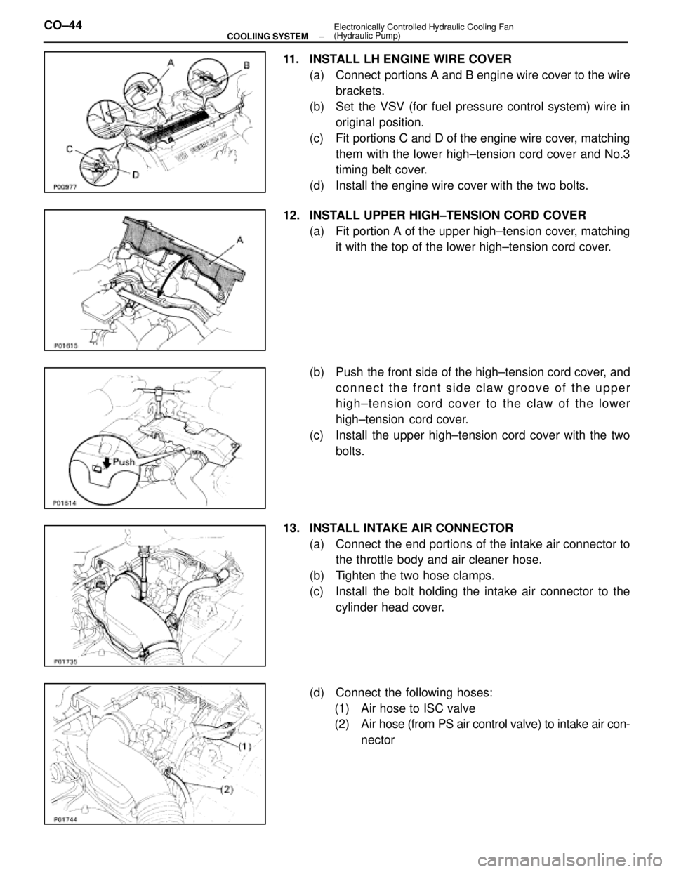
11. INSTALL LH ENGINE WIRE COVER(a) Connect portions A and B engine wire cover to the wirebrackets.
(b) Set the VSV (for fuel pressure control system) wire in
original position.
(c) Fit portions C and D of the engine wire cover, matching them with the lower high±tension cord cover and No.3
timing belt cover.
(d) Install the engine wire cover with the two bolts.
12. INSTALL UPPER HIGH±TENSION CORD COVER (a) Fit portion A of the upper high±tension cover, matchingit with the top of the lower high±tension cord cover.
(b) Push the front side of the high±tension cord cover, and connect the front side claw groove of the upper
high±tension cord cover to the claw of the lower
high±tension cord cover.
(c) Install the upper high±tension cord cover with the two bolts.
13. INSTALL INTAKE AIR CONNECTOR (a) Connect the end portions of the intake air connector tothe throttle body and air cleaner hose.
(b) Tighten the two hose clamps.
(c) Install the bolt holding the intake air connector to the cylinder head cover.
(d) Connect the following hoses: (1) Air hose to ISC valve
(2) Air hose (from PS air control valve) to intake air con- nector
CO±44
±
COOLIING SYSTEM Electronically Controlled Hydraulic Cooling Fan
(Hydraulic Pump)
WhereEverybodyKnowsYourName
Page 2859 of 4087

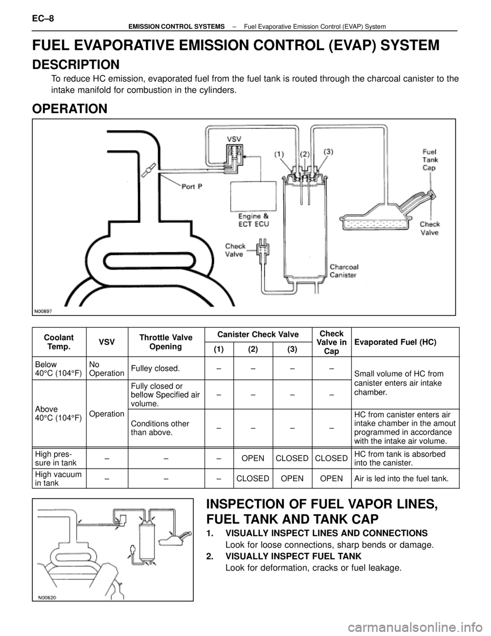
FUEL EVAPORATIVE EMISSION CONTROL (EVAP) SYSTEM
DESCRIPTION
To reduce HC emission, evaporated fuel from the fuel tank is routed throug\
h the charcoal canister to the
intake manifold for combustion in the cylinders.
OPERATION
CoolantVSVThrottle ValveCanister Check ValveCheck
Valve inEvaporated F el (HC)Coolant
Te m p .VSVThrottle Valve
Opening(1)(2)(3)Valve inCapEvaporated Fuel (HC)
BelowNoFulley closedBelow
40 5C (104 5F)
No
OperationFulley closed.±±±±Small volume of HC from
Fully closed or
bellow Specified air
canister enters air intake
chamber.
Above
bellow Specified air
volume.±±±±chamber.
Above
40 5C (104 5F)Operation
Conditions other
than above.±±±±
HC from canister enters air
intake chamber in the amout
programmed in accordance
with the intake air volume.
High pres-
sure in tank±±±OPENCLOSEDCLOSEDHC from tank is absorbed
into the canister.
High vacuum
in tank±±±CLOSEDOPENOPENAir is led into the fuel tank.
INSPECTION OF FUEL VAPOR LINES,
FUEL TANK AND TANK CAP
1. VISUALLY INSPECT LINES AND CONNECTIONS
Look for loose connections, sharp bends or damage.
2. VISUALLY INSPECT FUEL TANK Look for deformation, cracks or fuel leakage.
EC±8
±
EMISSION CONTROL SYSTEMS Fuel Evaporative Emission Control (EVAP) System
WhereEverybodyKnowsYourName
Page 2860 of 4087
3. VISUALLY INSPECT FUEL TANK CAPCheck if the cap and/or gasket are deformed or damaged.
If necessary, repair or replace the cap.
INSPECTION OF CHARCOAL CANISTER
1. REMOVE CHARCOAL CANISTER(a) Disconnect the following hoses:(1) Vacuum hose (from VSV) from charcoal canister
(2) EVAP hose from charcoal canister
(b) Disconnect the grommet on the check valve from the bracket, and remove the charcoal canister.
(c) Remove the check valve from the hose end on the charcoal canister.
2. VISUALLY INSPECT CHARCOAL CANISTER Look for cracks or damage.
3. CHECK FOR CLOGGED FILTER AND STUCK CHECK VA LV E
(a) Using low pressure compressed air, blow into port A and
check that air flows without resistance from the other
ports.
(b) Blow into port B and check that air does not flow from the
other ports.
If a problem is found, replace the charcoal canister.
±
EMISSION CONTROL SYSTEMS Fuel Evaporative Emission Control (EVAP) SystemEC±9
WhereEverybodyKnowsYourName