Page 1519 of 4087
15. DISCONNECT ENGINE WIRE CONNECTORS
16. DISCONNECT THEFT DETERRENT HORN CONNECTOR
17. DISCONNECT GROUND CABLE FROM BODY
18. DIS CO NNE CT PO WE R STE E RING (P S ) SO LE NO IDVALVE CONNECTOR
19. DISCONNECT WIRE CLAMP (FOR GENERATOR) FROM VSV (FOR EVAP)
(a) Remove the 2 bolts, and disconnect the VSV from the RH
cylinder head.
(b) Disconnect the wire clamp from the VSV bracket.
20. REMOVE GENERATOR
(a) Disconnect the generator connector.
(b) Remove the cap and nut, and disconnect the generator wire.
(c) Remove the bolt, and disconnect the transmission oil cooler pipe bracket from the generator.
(d) Remove the nut and generator.
21. DISCONNECT POWER STEERING (PS) TUBES FROM SUSPENSION CROSSMEMBER
Remove the clamp bolt, and disconnect the PS tubes.
±
1UZ±FE ENGINE ENGINE MECHANICALEG±143
WhereEverybodyKnowsYourName
Page 1525 of 4087
36. DISCONNECT TRANSMISSION CONTROL ROD FROMSHIFT LEVER
Remove the nut, and disconnect the control rod from the shift
lever.
37. REMOVE ENGINE AND TRANSMISSION A SSEMBLY
FROM VEHICLE
(a) Attach the engine chain hoist to the engine hangers.
(b) Remove the 2 nuts holding the engine mounting insulators to
the front suspension crossmember.
(c) Remove the 4 bolts, 4 nuts and rear engine m ounting
member. Disconnect the ground strap.
(d) Lift the engine out of the vehicle slowly and carefully. HINT: Make sure the engine is clear of all wirings, hoses and
cables.
NOTICE: Be careful not hit the PS gear housing, PNP switch
and ABS actuator.
(e) Place the engine and transmission assembly onto the stand.
±
1UZ±FE ENGINE ENGINE MECHANICALEG±149
WhereEverybodyKnowsYourName
Page 1568 of 4087
ENGINE INSTALLATION
EG2HW±02
(See Components for Engine Removal and Installation)
1. INSTALL ENGINE AND TRANSMISSION ASSEMBLY INVEHICLE
(a) Attach the engine chain hoist to the engine hangers.
(b) Slowly lower the engine and transmission assembly into the engine compartment.
NOTICE: Be careful not to hit the PS gear housing and
PNP switch.
(c) Insert the stud bolts of the front engine mounting brackets into the stud bolt holes of the front suspension crossmember.
(d) Keep the engine level.
(e) Install the rear engine mounting member with the 4 bolts and 4 nuts.
Torque:
25 NVm (250 kgf Vcm, 19 ft Vlbf) for bolt
13 N Vm (135 kgf Vcm, 10 ft Vlbf) for nut
(f) Install the 2 nuts holding the engine mounting brackets to the
front suspension crossmember.
Torque: 59 N Vm (600 kgf Vcm, 43 ft Vlbf)
EG±192±
1UZ±FE ENGINE ENGINE MECHANICAL
WhereEverybodyKnowsYourName
Page 1593 of 4087
35. DISCONNECT TRANSMISSION CONTROL RODRemove the nut, and disconnect the control rod from the shift
lever.
36. REMOVE ENGINE AND TRANSMISSION A SSEMBLY
FROM VEHICLE
(a) Attach the engine hoist chain to the engine hangers.
(b) Remove the two nuts holding the engine mounting insulators to the front suspension crossmember.
(c) Remove the four bolts, four nuts and rear engine mounting member. Disconnect the ground strap.
(d) Lift the engine out of the vehicle slowly and carefully.
NOTICE: Be careful not to hit the PS gear housing, neu-
tral start switch and ABS actuator.
(e) Make sure the engine is clear of all wiring, hoses and cables.
(f) Place the engine and transmission assembly onto the stand.
EM±128
±
ENGINE MECHANICAL Cylinder Block
WhereEverybodyKnowsYourName
Page 1632 of 4087

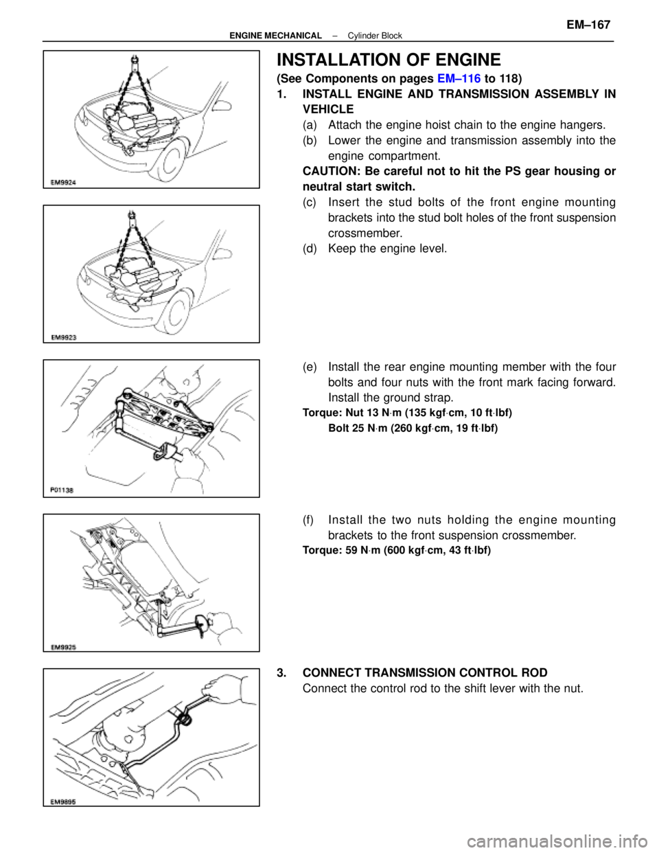
INSTALLATION OF ENGINE
(See Components on pages EM±116 to 118)
1. INSTALL ENGINE AND TRANSMISSION ASSEMBLY IN VEHICLE
(a) Attach the engine hoist chain to the engine hangers.
(b) Lower the engine and transmission assembly into the
engine compartment.
CAUTION: Be careful not to hit the PS gear housing or
neutral start switch.
(c) Insert the stud bolts of the front engine m ounting
brackets into the stud bolt holes of the front suspension
crossmember.
(d) Keep the engine level.
(e) Install the rear engine mounting member with the four
bolts and four nuts with the front mark facing forward.
Install the ground strap.
Torque: Nut 13 N Vm (135 kgf Vcm, 10 ft Vlbf)
Bolt 25 N Vm (260 kgf Vcm, 19 ft Vlbf)
(f) In sta ll th e two nu ts ho ld in g th e en g in e m ounting
brackets to the front suspension crossmember.
Torque: 59 N Vm (600 kgf Vcm, 43 ft Vlbf)
3. CONNECT TRANSMISSION CONTROL ROD
Connect the control rod to the shift lever with the nut.
±
ENGINE MECHANICAL Cylinder BlockEM±167
WhereEverybodyKnowsYourName
Page 1827 of 4087
(b) Place the matchmarks on the both flanges.
(c) Remove the four bolts, washers, nuts and intermediateshaft.
(d) Insert SST in transmission to prevent oil leakage.
SST 09325±20010 (M/T)
09325±40010 (A/T)
21. REMOVE ENGINE AND T RANSMISSION ASSEMBLY
FROM VEHICLE
(a) Attach the engine hoist chain to the engine hangers.
(b) Remove the two nuts holding the engine to the front suspension crossmember.
(c) Remove the four bolts, four nuts and rear engine mounting member.
(d) Lift the engine out of the vehicle slowly and carefully.
NOTICE: Remove carefully without damaging the power
steering gear housing or the park/neutral position switch
(A/T only).
(e) Make sure the engine is clear of all wiring, hoses and cables.
(f) Place the engine and transmission assembly onto the
stand.
EM±72
±
ENGINE MECHANICAL Cylinder Block
WhereEverybodyKnowsYourName
Page 1859 of 4087

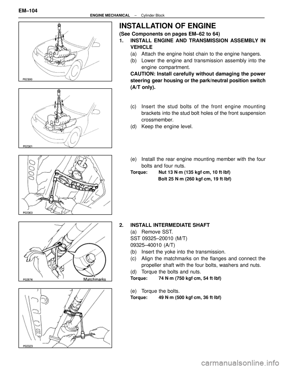
INSTALLATION OF ENGINE
(See Components on pages EM±62 to 64)
1. INSTALL ENGINE AND TRANSMISSION ASSEMBLY INVEHICLE
(a) Attach the engine hoist chain to the engine hangers.
(b) Lower the engine and transmission assembly into the
engine compartment.
CAUTION: Install carefully without damaging the power
steering gear housing or the park/neutral position switch
(A/T only).
(c) Insert the stud bolts of the front engine m ounting
brackets into the stud bolt holes of the front suspension
crossmember.
(d) Keep the engine level.
(e) Install the rear engine mounting member with the four bolts and four nuts.
Torque: Nut 13 N Vm (135 kgf Vcm, 10 ft Vlbf)
Bolt 25 N Vm (260 kgf Vcm, 19 ft Vlbf)
2. INSTALL INTERMEDIATE SHAFT
(a) Remove SST.
SST 09325±20010 (M/T)
09325±40010 (A/T)
(b) Insert the yoke into the transmission.
(c) Align the matchmarks on the flanges and connect thepropeller shaft with the four bolts, washers and nuts.
(d) Torque the bolts and nuts.
Torque: 74 N Vm (750 kgf Vcm, 54 ft Vlbf)
(e) Torque the bolts.
Torque: 49 N Vm (500 kgf Vcm, 36 ft Vlbf)
EM±104±
ENGINE MECHANICAL Cylinder Block
WhereEverybodyKnowsYourName
Page 2151 of 4087

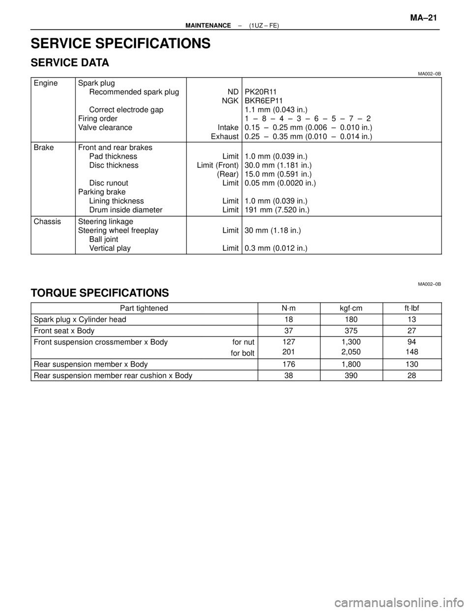
SERVICE SPECIFICATIONS
SERVICE DATA
MA002±0B����� �
����
�
����
�
����
�
����
�����
Engine���������� �
���������
�
���������
�
���������
�
���������
����������
Spark plug
Recommended spark plug
Correct electrode gap
Firing order
Valve clearance������ �
�����
�
�����
�
�����
�
�����
������
ND
NGK
Intake
Exhaust
������������������\
�
�����������������
�
�����������������
�
�����������������
�
�����������������
������������������\
PK20R11
BKR6EP11
1.1 mm (0.043 in.)
1 ± 8 ± 4 ± 3 ± 6 ± 5 ± 7 ± 2
0.15 ± 0.25 mm (0.006 ± 0.010 in.)
0.25 ± 0.35 mm (0.010 ± 0.014 in.)
����� �
����
�
����
�
����
�����
BrakeFront and rear brakes
Pad thickness
Disc thickness
Limit
Limit (Front) (Rear)1.0 mm (0.039 in.)
30.0 mm (1.181 in.)
15.0 mm (0.591 in.)
����� �
����
�
����
�����
Disc runout
Parking brake
Lining thickness
Drum inside diameter
()
Limit
Limit
Limit
()
0.05 mm (0.0020 in.)
1.0 mm (0.039 in.)
191 mm (7.520 in.)
����� �����ChassisSteering linkage
Steering wheel freeplay
Limit30 mm (1.18 in.)����� �
����
�����
gy
Ball joint
Vertical play
Limit
()
0.3 mm (0.012 in.)
MA002±0B
TORQUE SPECIFICATIONS
������������������\
�� ������������������\
��Part tightened������� �������N
Vm������ ������kgf Vcm������ ������ft Vlbf
���������������� ����������������Spark plug x Cylinder head1818013
���������������� ����������������Front seat x Body3737527
���������������� ����������������Front suspension crossmember x Body����� �����for nut1271,30094
���������������� ��������������������� �����for bolt 201
,
2,050148
���������������� ����������������Rear suspension member x Body1761,800130
���������������� ����������������Rear suspension member rear cushion x Body3839028
±
MAINTENANCE (1UZ ± FE)MA±21
WhereEverybodyKnowsYourName