Page 1235 of 4087
BO6847
mm (in.)
(Two-Dimensional Distance)
Hole dia.
18 (0.71) 18 (0.71)
10 (0.39) screw
12 (0.47) screw
Name
Front floor reinforcement standard hole
Rear floor side member standard hole
Suspension member bracket installation nut rear = outer
Transport hook installation nut front = outer
Symbol
L, l
M, m P, p
Q, q
Hole dia.
6 (0.24) screw
18 (0.71)
13 (0.51)
18 (0.71)
Name
Radiator duct installation nut
Front side member standard hole
Front suspension crossmember installation hole
Front side member standard hole
Symbol
A, aD, d F, f
I, i
UNDER BODY (Cont'd)
BODY DIMENSIONSDI-6
WhereEverybodyKnowsYourName
Page 1236 of 4087
BO6847
NOTICE: True up the mounting section ofthe front airbag sensor very carefully and
accurately so that the sensor can bemounted at the correct angle.
Imaginary
Standard
Line
mm (in.)
(Two-Dimensional Distance)
Hote dia.
10 (0.39) nut
10 (0.33) nut
18 (0.71)
14 (0.55) nut 9 (0.35)
Name
Engine rear mounting member installation nut-front Propeller shaft center support bearing installation nut
Front floor reinforcement standard hole
Rear suspension member installation nut Rear spring support hole-front
Symbol
J, j
K, k
L, l
N, n
O, o
Hole dia.
9 (0.35)
9 (0.35)
8 (0.31) nut
13 y11 (0.51 y0.43)14 (0.55) nut
Name
Front crossmember working hole
Airbag front sensor installation hole
Airbag front sensor installation nut Front spring support hole = outer
Front suspension crossmember installation nut
Symbol
B, b
C, c
E, e
G, g H, h
UNDER BODY (Cont'd)
BODY DIMENSIONSDI-7
WhereEverybodyKnowsYourName
Page 1239 of 4087
mm (in.)
BO6850
BO6850
(Three-Dimensional Distance) (Three-Dimensional Distance)
SymbolName Hole dia. Symbol Name
Hole dia.
A, a Steering gear box installation hole
front 12 (0.47)
E, eLower arm installation hole-front
25
y16
(0.98 y0.63)
B, b Upper arm installation hole front 14 (0.55) F, f Lower arm installation hole rear25
y16
(0.98 y0.63)
C, c Suspension crossmember installation
hole front - lower
15 (0.59) G, g Upper arm installation hole rear
14 (0.55)
D, d Steering gear box installation hole-
lower 12 (0.47)
H, hSuspension crossmember installation
hole rear-lower
RH 15
y13 (0.59 y0.51)
LH 13 (0.51)
SUSPENSION CROSSMEMBER DIMENSION DRAWINGS
BODY DIMENSIONSDI-10
WhereEverybodyKnowsYourName
Page 1240 of 4087
mm (in.)
BO6851
BO6851
(Two-Dimensional Distance) (Three-Dimensional Distance)
SymbolName Hole dia. Symbol Name Hole die.
I, i Suspension crossmember installation
hole front-lower
18 (0.71) L, lSuspension crossmember installation
hole rear-lower 18 (0.71)
J, j Lower arm installation hole-front 30
y16
(1.18 y0.63) M, mSuspension crossmember installation
hole rear-lower
18 (0.71)
K, k Lower arm installation hole rear 30
y16
(1.18 y0.63)
Suspension Crossmember (Cont'd)
BODY DIMENSIONSDI-11
WhereEverybodyKnowsYourName
Page 1241 of 4087
mm (in.)
BO6852
BO6852
(Two-Dimensional Distance) (Three-Dimensional Distance)
SymbolName Hole dia.
Symbol Name Hole dia.
A, a Strut bar installation hole inner
14 (0.55)F, fLower arm installation hole front 26
y14
(1.02 y0.55)
B, b Differential carrier installation nut 12 (0.47) nut G, gRear suspension member standard
hole
20 (0.78)
C, c Rear suspension member standard
hole 20 (0.78)
H, hLower arm installation hole rear 26
y14
(1.02 y0.55)
D, d Lower arm installation hole front 26
yl4
1.02 y0.55 I, i
Upper arm installation hole rear 14 (0.55)
E, e Upper arm installation hole front 14 (0.55)
Suspension Crossmember (Cont'd)
BODY DIMENSIONSDI-12
WhereEverybodyKnowsYourName
Page 1248 of 4087

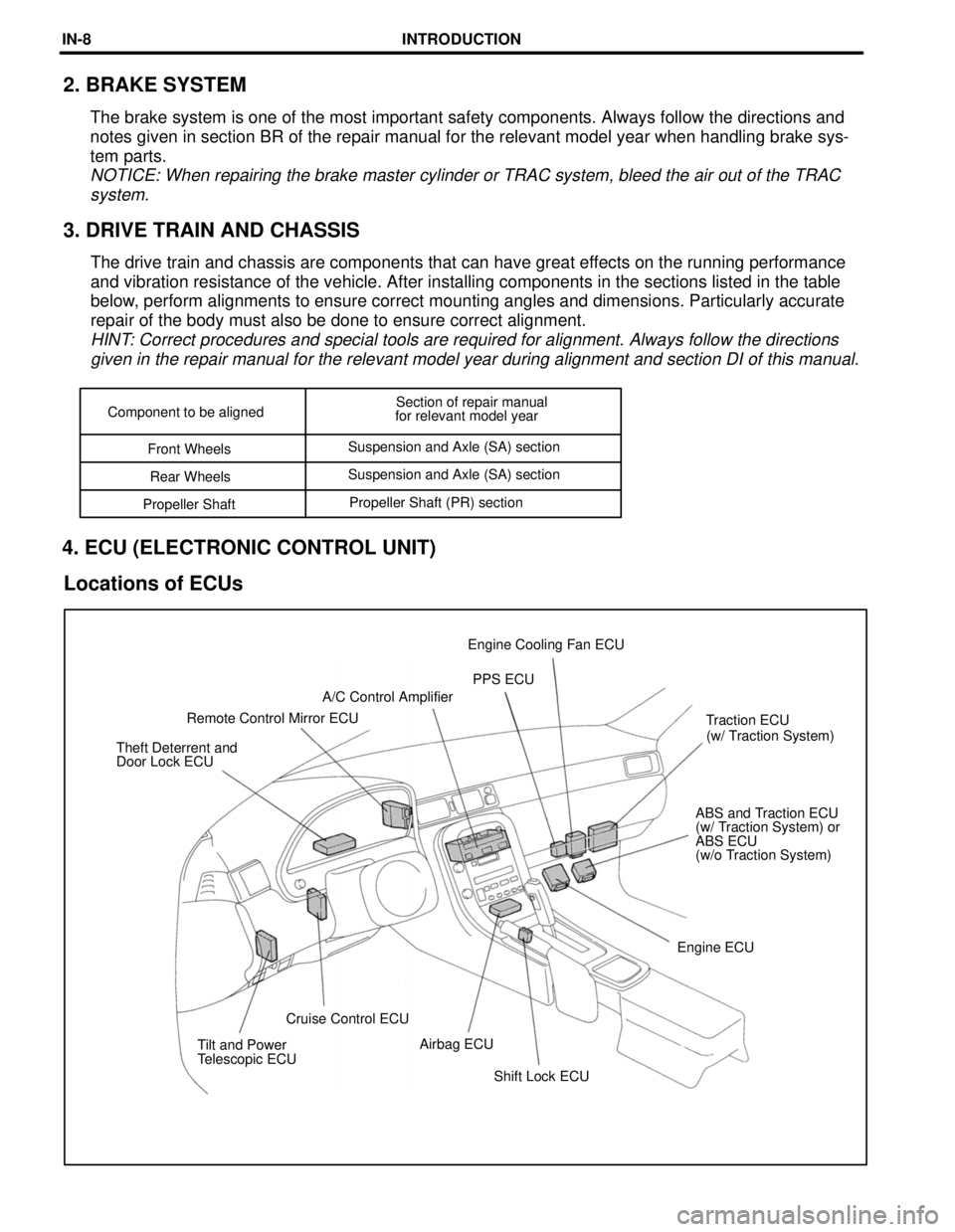
Shift Lock ECU
Tilt and Power
Telescopic ECU
Airbag ECU
Cruise Control ECU Engine ECUABS and Traction ECU
(w/ Traction System) or
ABS ECU
(w/o Traction System)
Theft Deterrent and
Door Lock ECU
(w/ Traction System)
Traction ECU
Remote Control Mirror ECU A/C Control Amplifier
PPS ECU
Engine Cooling Fan ECU
Component to be aligned
Section of repair manual
for relevant model year
Front Wheels Suspension and Axle (SA) section
Rear Wheels Suspension and Axle (SA) section
Propeller Shaft Propeller Shaft (PR) section
2. BRAKE SYSTEM
The brake system is one of the most important safety components. Always \
follow the directions and
notes given in section BR of the repair manual for the relevant model ye\
ar when handling brake sys-
tem parts.
NOTICE: When repairing the brake master cylinder or TRAC system, bleed t\
he air out of the TRAC
system.
3. DRIVE TRAIN AND CHASSIS
The drive train and chassis are components that can have great effects on the running performance
and vibration resistance of the vehicle. After installing components in \
the sections listed in the table
below, perform alignments to ensure correct mounting angles and dimensions. P\
articularly accurate
repair of the body must also be done to ensure correct alignment.
HINT: Correct procedures and special tools are required for alignment. Alway\
s follow the directionsgiven in the repair manual for the relevant model year during alignment \
and section DI of this manual.
4. ECU (ELECTRONIC CONTROL UNIT)
Locations of ECUs
INTRODUCTIONIN-8
WhereEverybodyKnowsYourName
Page 1255 of 4087
N01093
N01094
SUPPORT POSITION PANTOGRAPH JACK POSITION
Front Center of suspension crossmember. . . . . . . .
Rear Jack up support of differential carrier . . . . . . . . .
JACK POSITION
Jack
or Suspension Crossmember
Front
Safety stand . . . . . . . . . . . . . . . . . . . . . . . . . . . . . . . . . . . . . . . . . . . . . . . . . . . . . .
VEHICLE LIFT AND SUPPORT LOCATIONS
INTRODUCTIONIN-15
WhereEverybodyKnowsYourName
Page 1375 of 4087

������������������\
� ������������������\
�
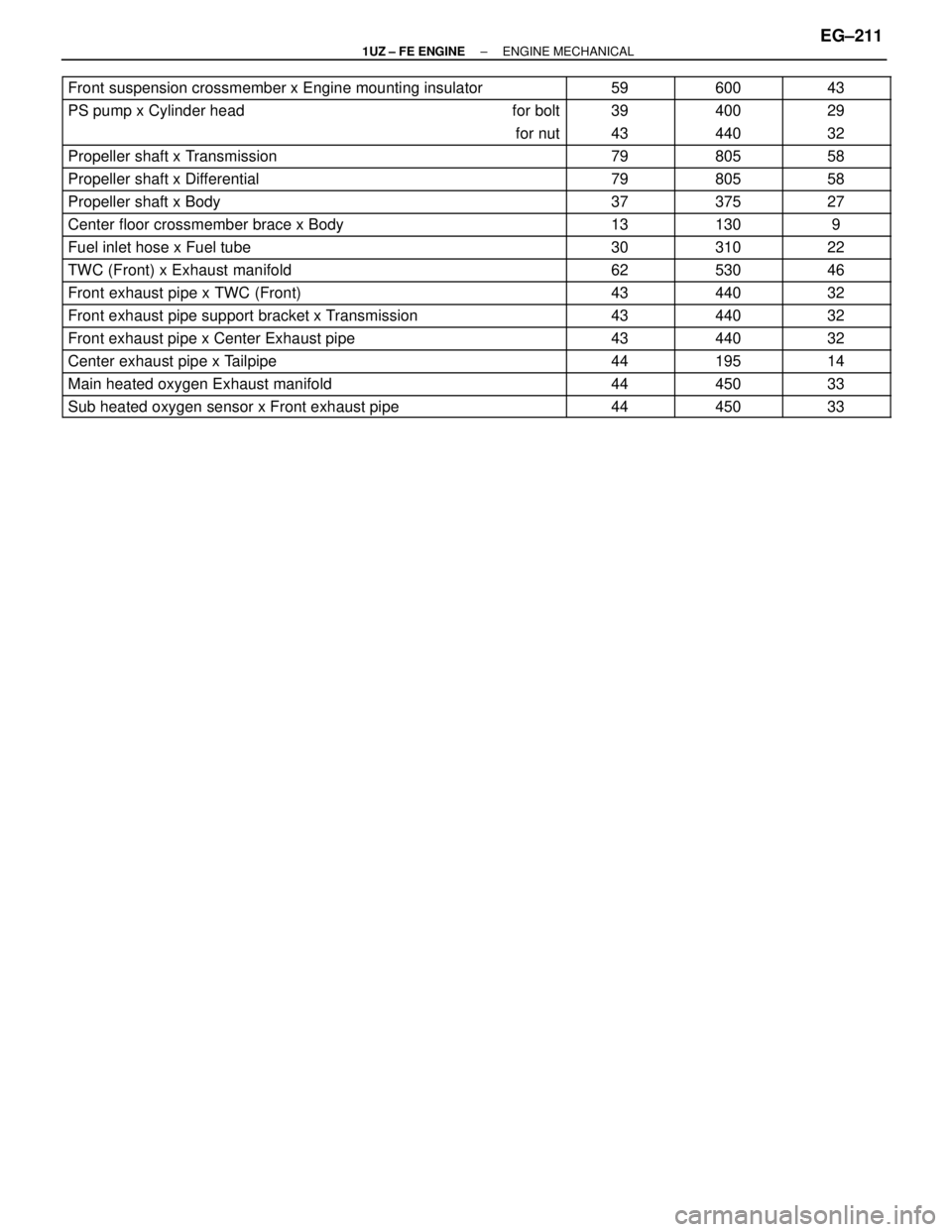
Front suspension crossmember x Engine mounting insulator���� ���������� ������59����� �����600������ ������43
������������������\
� ������������������\
�PS pump x Cylinder head���� ����for bolt������ ������39����� �����400������ ������29
������������������\
� ������������������\
����� ����for nut������ ������43����� �����440������ ������32
������������������\
� ������������������\
�Propeller shaft x Transmission���� ���������� ������79����� �����805������ ������58������������������\
� ������������������\
�
Propeller shaft x Differential
���� ���������� ������
79
����� �����
805
������ ������
58������������������\
� ������������������\
�
Propeller shaft x Body
���� ���������� ������
37
����� �����
375
������ ������
27������������������\
� ������������������\
�Center floor crossmember brace x Body���� ���������� ������13����� �����130������ ������9������������������\
� ������������������\
�Fuel inlet hose x Fuel tube���� ���������� ������30����� �����310������ ������22������������������\
� ������������������\
�TWC (Front) x Exhaust manifold���� ���������� ������62����� �����530������ ������46������������������\
� ������������������\
�Front exhaust pipe x TWC (Front)���� ���������� ������43����� �����440������ ������32������������������\
� ������������������\
�Front exhaust pipe support bracket x Transmission���� ���������� ������43����� �����440������ ������32������������������\
� ������������������\
�Front exhaust pipe x Center Exhaust pipe���� ���������� ������43����� �����440������ ������32������������������\
� ������������������\
�Center exhaust pipe x Tailpipe���� ���������� ������44����� �����195������ ������14
������������������\
� ������������������\
�Main heated oxygen Exhaust manifold���� ���������� ������44����� �����450������ ������33
������������������\
� ������������������\
�Sub heated oxygen sensor x Front exhaust pipe���� ���������� ������44����� �����450������ ������33
±
1UZ ± FE ENGINE ENGINE MECHANICALEG±211
WhereEverybodyKnowsYourName