Page 3214 of 4087
ASSEMBLY REMOVAL AND
INSTALLATION
COMPONENTS
SA09A±07
±
SUSPENSION AND AXLE REAR DIFFERENTIALSA±81
WhereEverybodyKnowsYourName
Page 3215 of 4087
DIFFERENTIAL REMOVAL
SA0S6±05
1. REMOVE PROPELLER SHAFT(See page PR±6 or 24)
2. DRAIN DIFFERENTIAL OIL
3. DISCONNECT REAR DRIVE SHAFTS
(a) Place matchmarks on the drive shafts and side gear shafts.
(b) Using a hexagon wrench, disconnect the drive shafts from
the differential.
(c) Hang up the drive shafts using wire, etc.
4. REMOVE DIFFERENTIAL
(a) Support the differential with a jack.
(b) Using a hexagon wrench, remove the 3 bolts.
(c) Remove the 2 bolts and lower stoppers.
(d) Remove the differential.
SA±82
±
SUSPENSION AND AXLE REAR DIFFERENTIAL
WhereEverybodyKnowsYourName
Page 3216 of 4087

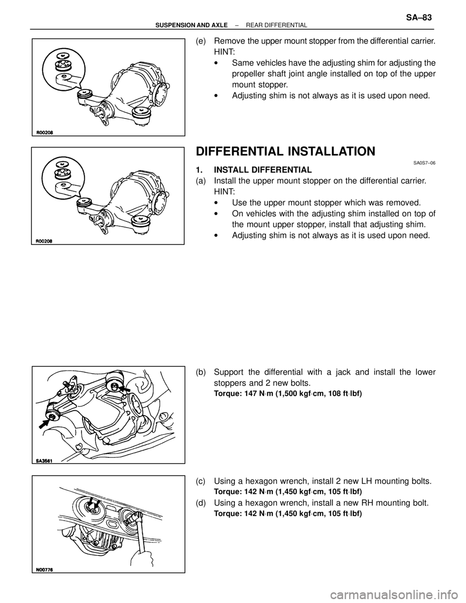
(e) Remove the upper mount stopper from the differential carrier.
HINT:
w Same vehicles have the adjusting shim for adjusting the
propeller shaft joint angle installed on top of the upper
mount stopper.
w Adjusting shim is not always as it is used upon need.
DIFFERENTIAL INSTALLATION
SA0S7±06
1. INSTALL DIFFERENTIAL
(a) Install the upper mount stopper on the differential carrier.
HINT:
wUse the upper mount stopper which was removed.
w On vehicles with the adjusting shim installed on top of
the mount upper stopper, install that adjusting shim.
w Adjusting shim is not always as it is used upon need.
(b) Support the differential with a jack and install the lower stoppers and 2 new bolts.
Torque: 147 N Vm (1,500 kgf Vcm, 108 ft Vlbf)
(c) Using a hexagon wrench, install 2 new LH mounting bolts.
Torque: 142 N Vm (1,450 kgf Vcm, 105 ft Vlbf)
(d) Using a hexagon wrench, install a new RH mounting bolt.
Torque: 142 N Vm (1,450 kgf Vcm, 105 ft Vlbf)
±
SUSPENSION AND AXLE REAR DIFFERENTIALSA±83
WhereEverybodyKnowsYourName
Page 3217 of 4087
2. CONNECT REAR DRIVE SHAFTS
(a) Align the matchmarks on the side gear shaft and drive shafts.
(b) Apply a light coat of engine oil on the threads of the bolts.
(c) Temporarily install the 12 hexagon bolts and 4 washers.
(d) Using a hexagon wrench, torque the bolts.
Torque: 83 N Vm (850 kgf Vcm, 61 ft Vlbf)
3. INSTALL PROPELLER SHAFT
(See page PR±12 or 28)
4. FILL DIFFERENTIAL WITH OIL
Oil grade: API GL±5 Hypoid Gear Oil
Viscosity: Above±18 �C (0 �F) SAE 90
Below±18 �C (0 �F) SAE 80W±90 or 80W
Capacity:
1.35 liters (1.42 US qts, 1.19 lmp qts)
SA±84±
SUSPENSION AND AXLE REAR DIFFERENTIAL
WhereEverybodyKnowsYourName
Page 3218 of 4087
DIFFERENTIAL CARRIER
COMPONENTS
SA0V2±01
±
SUSPENSION AND AXLE REAR DIFFERENTIALSA±85
WhereEverybodyKnowsYourName
Page 3219 of 4087

DIFFERENTIAL CARRIER INSPECTION
SA0V3±05
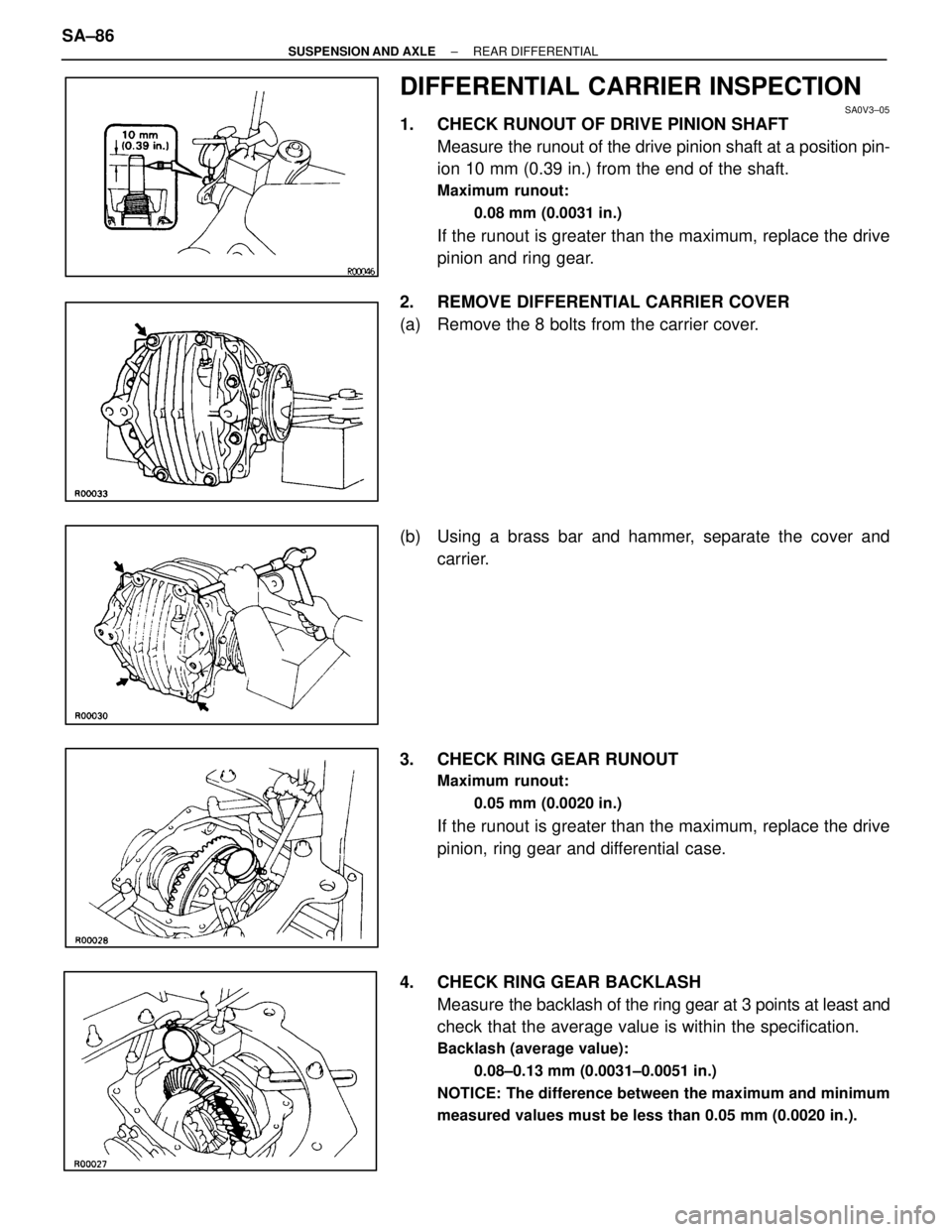
1. CHECK RUNOUT OF DRIVE PINION SHAFTMeasure the runout of the drive pinion shaft at a position pin-
ion 10 mm (0.39 in.) from the end of the shaft.
Maximum runout:
0.08 mm (0.0031 in.)
If the runout is greater than the maximum, replace the drive
pinion and ring gear.
2. REMOVE DIFFERENTIAL CARRIER COVER
(a) Remove the 8 bolts from the carrier cover.
(b) Using a brass bar and hammer, separate the cover and carrier.
3. CHECK RING GEAR RUNOUT
Maximum runout: 0.05 mm (0.0020 in.)
If the runout is greater than the maximum, replace the drive
pinion, ring gear and differential case.
4. CHECK RING GEAR BACKLASH Measure the backlash of the ring gear at 3 points at least and
check that the average value is within the specification.
Backlash (average value):
0.08±0.13 mm (0.0031±0.0051 in.)
NOTICE: The difference between the maximum and minimum
measured values must be less than 0.05 mm (0.0020 in.).
SA±86±
SUSPENSION AND AXLE REAR DIFFERENTIAL
WhereEverybodyKnowsYourName
Page 3220 of 4087

If the backlash is not within the specification, adjust the back-
lash. (See page SA±98)
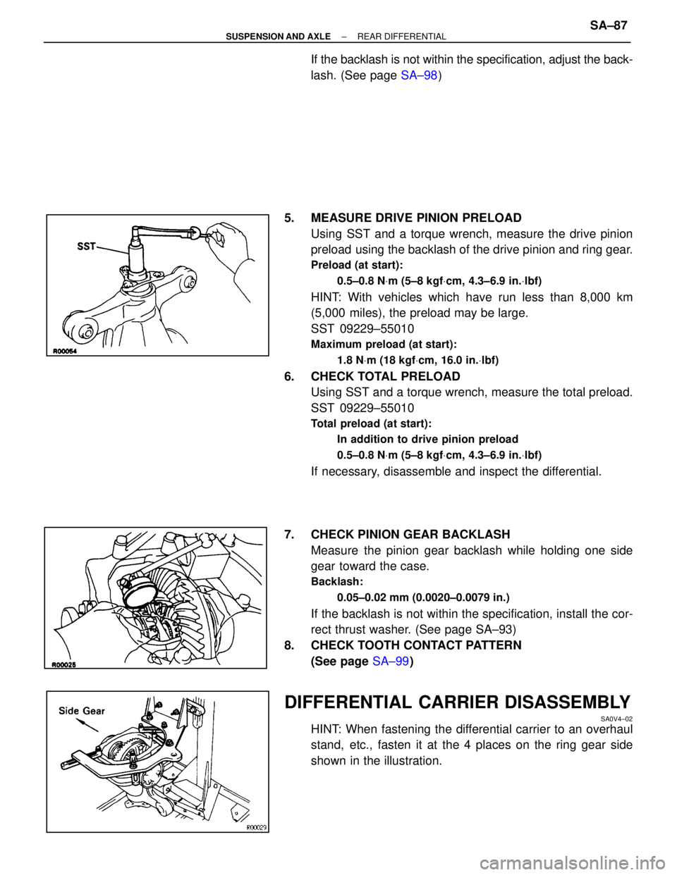
5. MEASURE DRIVE PINION PRELOAD Using SST and a torque wrench, measure the drive pinion
preload using the backlash of the drive pinion and ring gear.
Preload (at start):
0.5±0.8 N Vm (5±8 kgf Vcm, 4.3±6.9 in. Vlbf)
HINT: With vehicles which have run less than 8,000 km
(5,000 miles), the preload may be large.
SST 09229±55010
Maximum preload (at start):
1.8 N Vm (18 kgf Vcm, 16.0 in. Vlbf)
6. CHECK TOTAL PRELOAD
Using SST and a torque wrench, measure the total preload.
SST 09229±55010
Total preload (at start):
In addition to drive pinion preload
0.5±0.8 N Vm (5±8 kgf Vcm, 4.3±6.9 in. Vlbf)
If necessary, disassemble and inspect the differential.
7. CHECK PINION GEAR BACKLASH Measure the pinion gear backlash while holding one side
gear toward the case.
Backlash:
0.05±0.02 mm (0.0020±0.0079 in.)
If the backlash is not within the specification, install the cor-
rect thrust washer. (See page SA±93)
8. CHECK TOOTH CONTACT PATTERN (See page SA±99)
DIFFERENTIAL CARRIER DISASSEMBLY
SA0V4±02
HINT: When fastening the differential carrier to an overhaul
stand, etc., fasten it at the 4 places on the ring gear side
shown in the illustration.
±
SUSPENSION AND AXLE REAR DIFFERENTIALSA±87
WhereEverybodyKnowsYourName
Page 3221 of 4087
1. REMOVE SIDE GEAR SHAFTUsing SST, remove the side gear shaft.
SST 09520±24010
NOTICE: Be careful not to damage the oil seal.
2. REMOVE SIDE GEAR SHAFT OIL SEALSUsing SST, remove the oil seals.
SST 09308±00010
3. REMOVE DIFFERENTIAL CARRIER RETAINER
(a) Remove the 8 bolts.
(b) Using SST, remove the carrier retainer. SST 09950±20017
4. REMOVE DIFFERENTIAL CASE Take the differential case out of the carrier while lifting the ring
gear side, as shown in the illustration.
SA±88
±
SUSPENSION AND AXLE REAR DIFFERENTIAL
WhereEverybodyKnowsYourName