Page 2154 of 4087
V04535
(4) Also applicable to drum lining for parking brake. For other usage condit\
ions, refer to SCHEDULE B.
(5) Check for leakage.
(6) Check for oil leaks from steering gear housing.
(7) Applicable only when operating mainly on rough, muddy roads. The applicable parts \
are listed below. Forother usage conditions, refer to SCHEDULE B.
�Front and rear suspension member to cross body.
� Bolts for seat installation.
±
MAINTENANCE (1UZ ± FE)MA±3
WhereEverybodyKnowsYourName
Page 2155 of 4087
MA033±0C
SCHEDULE B
CONDITIONS:
Conditions others than those listed for SCHEDULE A.Maintenance operation: A = Check and adjust if necessary. R = Replace, change or lubricate.
I = Inspect and correct or replace if necessary.
V04409
� mark indicates maintenance which is part of the warranty conditions for\
the Emission Control Systems.
The warranty period is in accordance with the owner's guide or the warranty booklet.
( � : California and New York specification vehicles only)
(1) Includes inspection of fuel tank band and vaper vent system.
(2) Also applicable to drum lining for parking brake.
(3) Check for leakage.
(4) Check for oil leaks from steering gear housing.
(5) The applicable parts are listed below. �Front and rear suspension member to cross body.
� Bolts for seat installation.
MA±4
±
MAINTENANCE (1UZ ± FE)
WhereEverybodyKnowsYourName
Page 2166 of 4087

20. INSPECT BALL JOINTS AND DUST COVERS
(a) Inspect the ball joints for excessive looseness.wJack up the front of the vehicle and support it with
stands.
w Make sure the front wheels are in a straight±ahead
position, and depress the brake pedal.
w Jack up the lower suspension arm until there is about
half a load on the front coil spring.
w Move the front wheel up and down and check that the
ball joint has no excessive play.
Maximum lower ball joint vertical play.
0.3 mm (0.012 in.)
If the play is greater than maximum, replace the ball joint.
(b) Visually check the dust covers for damage
21. C H E C K A U TO M AT I C T RANSMISSION AND
DIFFERENTIAL OIL (FLUID)
A. Inspect automatic transmission fluid
(a) Visually check the differential for fluid and leakage.
If leakage is found, check for the cause and repair.
(b) Check the fluid level with the engine idling and shift lever at ªPº.
If the level is low, add fluid.
Transmission fluid:
See item 22 (A)
B. Inspect differential oil
(a) Visually check the transmission for oil and leakage.If leakage is found, check for the cause and repair.
(b) Remove the filler plug, and feel inside the hole with your finger. Check that the oil comes to within 5 mm (0.20 in) of the
bottom edge of the filler hole.
If the level is low, add oil until it begins to run out of the filler
hole.
±
MAINTENANCE (1UZ ± FE)MA±15
WhereEverybodyKnowsYourName
Page 2168 of 4087

ViscosityAbove ± 185C (05F) SAE 90
Below ± 18 5C (0 5F) SAE 80W±90 or 80W
Capacity:
1.35 liters (1.43 US qts, 1.19 lmp. qts)
(e) Reinstall the filler plug securely.
23. TIGHTEN BOLTS AND NUTS ON CHASSIS AND BODY Tighten the following parts.
wFront seat±to±body mounting bolts
Torque: 37 N Vm (375 kgf Vcm, 27 ft Vlbf)
w Front suspension crossmembers - to - body mounting
nuts and bolts
Torque:
127 N Vm (1.300 kgf Vcm, 94 ft Vlbf) for nut
201 N Vm (2,050 kgf Vcm, 148 ft Vlbf) for bolt
w Rear suspension member - to - body mounting bolts
Torque: 176 NVm (1,800 kgfVcm, 130 ftVlbf)
wRear suspension member rear cushion - to - body
mounting bolts
Torque: 38 N Vm (390 kgf Vcm, 28 ft Vlbf)
24. BODY INSPECTION
(a) Check the body exterior for dents, scratches and rust
(b) Check the underbody for rust and damage.
If necessary, replace or repair.
25. ROAD TEST
(a) Check the engine and chassis for abnormal noises.
(b) Check that the vehicle does not wander or pull to one side.
(c) Check that the brakes work properly and do not drag.
(d) Perform setting of the parking brake shoes and drum.
±
MAINTENANCE (1UZ ± FE)MA±17
WhereEverybodyKnowsYourName
Page 2328 of 4087
35. DISCONNECT TRANSMISSION CONTROL RODRemove the nut, and disconnect the control rod from the shift
lever.
36. REMOVE ENGINE AND TRANSMISSION A SSEMBLY
FROM VEHICLE
(a) Attach the engine hoist chain to the engine hangers.
(b) Remove the two nuts holding the engine mounting insulators to the front suspension crossmember.
(c) Remove the four bolts, four nuts and rear engine mounting member. Disconnect the ground strap.
(d) Lift the engine out of the vehicle slowly and carefully.
NOTICE: Be careful not to hit the PS gear housing, neu-
tral start switch and ABS actuator.
(e) Make sure the engine is clear of all wiring, hoses and cables.
(f) Place the engine and transmission assembly onto the stand.
EM±128
±
ENGINE MECHANICAL Cylinder Block
WhereEverybodyKnowsYourName
Page 2367 of 4087

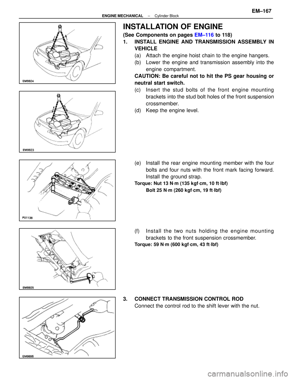
INSTALLATION OF ENGINE
(See Components on pages EM±116 to 118)
1. INSTALL ENGINE AND TRANSMISSION ASSEMBLY IN VEHICLE
(a) Attach the engine hoist chain to the engine hangers.
(b) Lower the engine and transmission assembly into the
engine compartment.
CAUTION: Be careful not to hit the PS gear housing or
neutral start switch.
(c) Insert the stud bolts of the front engine m ounting
brackets into the stud bolt holes of the front suspension
crossmember.
(d) Keep the engine level.
(e) Install the rear engine mounting member with the four
bolts and four nuts with the front mark facing forward.
Install the ground strap.
Torque: Nut 13 N Vm (135 kgf Vcm, 10 ft Vlbf)
Bolt 25 N Vm (260 kgf Vcm, 19 ft Vlbf)
(f) In sta ll th e two nu ts ho ld in g th e en g in e m ounting
brackets to the front suspension crossmember.
Torque: 59 N Vm (600 kgf Vcm, 43 ft Vlbf)
3. CONNECT TRANSMISSION CONTROL ROD
Connect the control rod to the shift lever with the nut.
±
ENGINE MECHANICAL Cylinder BlockEM±167
WhereEverybodyKnowsYourName
Page 2382 of 4087

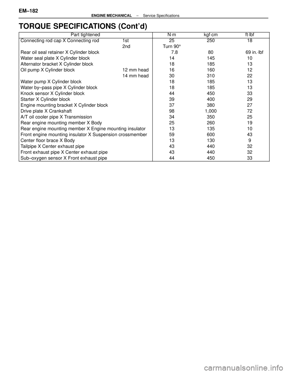
TORQUE SPECIFICATIONS (Cont'd)
������������������\
�� ������������������\
��Part tightened������ ������NVm������ ������kgf Vcm������� �������ft Vlbf
��������������� ���������������Connecting rod cap X Connecting rod������ ������1st������ ������25������ ������250������� �������18
���������������������2nd������Turn 90 5���������������������������� ���������������Rear oil seal retainer X Cylinder block������ ������������ ������ 7.8������ ������80������� ������� 69 in. Vlbf��������������� ���������������Water seal plate X Cylinder block������ ������������ ������14������ ������145������� �������10
��������������� ���������������Alternator bracket X Cylinder block������ ������������ ������18������ ������185������� �������13
��������������� ���������������Oil pump X Cylinder block������ ������12 mm head������ ������16������ ������160������� �������12
���������������������14 mm head������30������310�������22��������������� ���������������Water pump X Cylinder block������ ������������ ������18������ ������185������� �������13��������������� ���������������Water by±pass pipe X Cylinder block������ ������������ ������18������ ������185������� �������13
��������������� ���������������Knock sensor X Cylinder block������ ������������ ������44������ ������450������� �������33
��������������� ���������������Starter X Cylinder block������ ������������ ������39������ ������400������� �������29
���������������Engine mounting bracket X Cylinder block������������37������380�������27��������������� ���������������Drive plate X Crankshaft������ ������������ ������98������ ������1,000������� �������72��������������� ���������������A/T oil cooler pipe X Transmission������ ������������ ������34������ ������350������� �������25��������������� ���������������Rear engine mounting member X Body������ ������������ ������25������ ������260������� �������19
������������������\
�� ������������������\
��Rear engine mounting member X Engine mounting insulator������ ������13������ ������135������� �������10
������������������\
�� ������������������\
��Front engine mounting insulator X Suspension crossmember������ ������59������ ������600������� �������43
���������������Center floor brace X Body������������13������130�������9��������������� ���������������Tailpipe X Center exhaust pipe������ ������������ ������43������ ������440������� �������32��������������� ���������������Front exhaust pipe X Center exhaust pipe������ ������������ ������43������ ������440������� �������32
��������������� ���������������Sub±oxygen sensor X Front exhaust pipe������ ������������ ������44������ ������450������� �������33
EM±182±
ENGINE MECHANICAL Service Specifications
WhereEverybodyKnowsYourName
Page 3013 of 4087
TROUBLESHOOTING FLOW±CHART
SR0GT±04
Trouble
�Hard steering at idle or low±speed driving.
� Steering too sensitive during high±speed driving.
Preliminary Check
�Check tire pressure.
� Check lubrication of suspension and steering linkage.
� Check front wheel alignment.
� Check steering system joint and suspension arm ball joint.
� Check for bent steering column.
� Check that all connectors are secure.
� Check PS pump fluid pressure. (See page SR±115)
SR±164±
STEERING POWER STEERING
WhereEverybodyKnowsYourName