1991 FORD FESTIVA valve cover
[x] Cancel search: valve coverPage 101 of 454
Back To Article
ENGINE OVERHAUL
1991-92 FORD MOT OR CO. ENGINES 1.3L & 1.6L 4-Cylinder
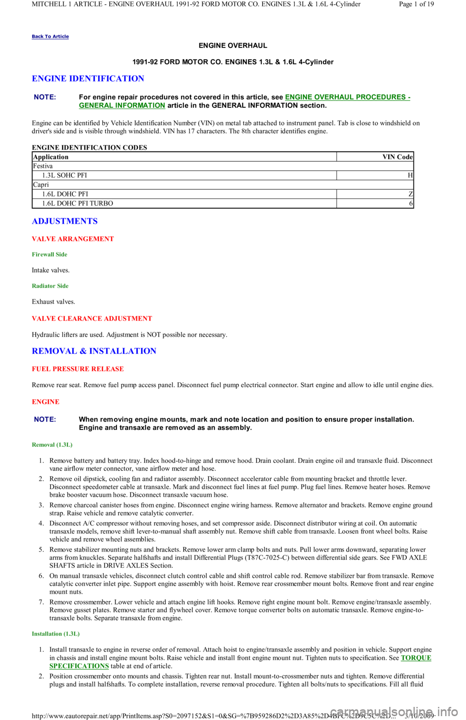
ENGINE IDENTIFICATION
Engine can be identified by Vehicle Identification Number (VIN) on metal tab attached to instrument panel. Tab is close to windshield on
driver's side and is visible through windshield. VIN has 17 characters. The 8th character identifies engine.
ENGINE IDENTIFICATION CODES
ADJUSTMENTS
VALVE ARRANGEMENT
Firewall Side
In t ake val ves.
Radiator Side
Exhaust valves.
VALVE CLEARANCE ADJUSTMENT
Hydraulic lifters are used. Adjustment is NOT possible nor necessary.
REMOVAL & INSTALLATION
FUEL PRESSURE RELEASE
Remove rear seat. Remove fuel pump access panel. Disconnect fuel pump electrical connector. Start engine and allow to idle until engine dies.
ENGINE
Removal (1.3L)
1. Remove battery and battery tray. Index hood-to-hinge and remove hood. Drain coolant. Drain engine oil and transaxle fluid. Disconnect
vane airflow meter connector, vane airflow meter and hose.
2. Remove oil dipstick, cooling fan and radiator assembly. Disconnect accelerator cable from mounting bracket and throttle lever.
Disconnect speedometer cable at transaxle. Mark and disconnect fuel lines at fuel pump. Plug fuel lines. Remove heater hoses. Remove
brake booster vacuum hose. Disconnect transaxle vacuum hose.
3. Remove charcoal canister hoses from engine. Disconnect engine wiring harness. Remove alternator and brackets. Remove engine ground
strap. Raise vehicle and remove catalytic converter.
4. Disconnect A/C compressor without removing hoses, and set compressor aside. Disconnect distributor wiring at coil. On automatic
transaxle models, remove shift lever-to-manual shaft assembly nut. Remove shift cable from transaxle. Loosen front wheel bolts. Raise
vehicle and remove wheel assemblies.
5. Remove stabilizer mounting nuts and brackets. Remove lower arm clamp bolts and nuts. Pull lower arms downward, separating lower
arms from knuckles. Separate halfshafts and install Differential Plugs (T87C-7025-C) between differential side gears. See FWD AXLE
SHAFTS article in DRIVE AXLES Section.
6. On manual transaxle vehicles, disconnect clutch control cable and shift control cable rod. Remove stabilizer bar from transaxle. Remove
catalytic converter inlet pipe. Support engine assembly with hoist. Remove rear crossmember mount bolts. Remove front and rear engine
mount nuts.
7. Remove crossmember. Lower vehicle and attach engine lift hooks. Remove right engine mount bolt. Remove engine/transaxle assembly.
Remove gusset plates. Remove starter and flywheel cover. Remove torque converter bolts on automatic transaxle. Remove engine-to-
transaxle bolts. Separate transaxle from engine.
Installation (1.3L)
1. Install transaxle to engine in reverse order of removal. Attach hoist to engine/transaxle assembly and position in vehicle. Support engine
in chassis and install engine mount bolts. Raise vehicle and install front engine mount nut. Tighten nuts to specification. See TORQUE
SPECIFICATIONS table at end of article.
2. Position crossmember onto mounts and chassis. Tighten rear nut. Install mount-to-crossmember nuts and tighten. Remove differential
plugs and install halfshafts. To complete installation, reverse removal procedure. Tighten all bolts/nuts to specifications. Fill all fluid NOTE:For engine repair procedures not covered in this article, see ENGINE OVERHAUL PROCEDURES
-
GENERAL INFORMATION
article in the GENERAL INFORMAT ION section.
ApplicationVIN Code
Festiva
1.3L SOHC PFIH
Capri
1.6L DOHC PFIZ
1.6L DOHC PFI TURBO6
NOTE:When rem oving engine m ounts, m ark and note location and position to ensure proper installation.
Engine and transaxle are rem oved as an assem bly.
Page 1 of 19 MITCHELL 1 ARTICLE - ENGINE OVERHAUL 1991-92 FORD MOTOR CO. ENGINES 1.3L & 1.6L 4-Cylinder
3/10/2009 http://www.eautorepair.net/app/PrintItems.asp?S0=2097152&S1=0&SG=%7B959286D2%2D3A85%2D4BFC%2D9C5C%2D
...
Page 104 of 454

1. Position new gasket on exhaust manifold, and install turbocharger onto studs. Install 4 retaining nuts and tighten to specification. See
TORQUE SPECIFICATIONS
table at end of article.
2. Remove oil supply line from turbocharger. Position new (2-piece) exhaust gasket on cylinder head with heavy gasket installed first .
Carefully position turbocharger assembly in engine compartment and slide exhaust manifold on studs. Position heater tube bracket onto
exhaust stud. Install 11 retaining nuts onto exhaust manifold and tighten to specification. See TORQUE SPECIFICATIONS
table at
end of article. Tighten heater tube clamp bolt securely.
3. Raise vehicle. Position new gasket and install 2 retaining bolts on heater tube outlet. Install 2 retaining bolts into turbocharger support
bracket and tighten bolts to specification.
4. Connect coolant return hose. Connect oil return hose and secure with clamp. Position exhaust pipe onto turbocharger, and start nuts
and washers. Install 2 retaining bolts on exhaust hanger at engine. Slide on 2 rubber exhaust hangers at catalytic converter. Tighten
exhaust pipe retaining nuts to specification. Lower vehicle.
5. Install retaining bolt and brass washers on oil supply line, carefully position oil line into vehicle and hand-start bolt into engine block.
Connect and finger tighten oil line to turbocharger. Tighten oil line bolt and oil supply line on turbocharger to specification.
6. Connect coolant supply hose. Position air cleaner duct tube on turbocharger and tighten clamp. Install 2 screws retaining air cleaner
duct tube. Position power steering pump bracket on engine, and install 2 retaining bolts and one retaining nut. Tighten to specification.
Position power steering pump on mounting bracket, and install though bolt and adjuster. Connect lower radiator hose. Install power
steering belt. Position upper heat shield and install 2 retaining bolts finger tight.
7. Position lower heat shield and install three retaining bolts finger tight. Tighten all heat shield bolts to specification. Connect O2 sensor
and install connector into its retaining clip. See TORQUE SPECIFICATIONS
table at end of article. Position intercooler hose on
turbocharger and secure with clamp. Install throttle body air intake tube. Connect negative battery cable. Refill cooling system.
CYLINDER HEAD
Removal (1.3L)
1. Disconnect battery ground cable. Mark and disconnect fuel lines at fuel pump. Remove accessory belts, water pump pulley, crankshaft
pulley, timing belt covers, timing belt tensioner, timing belt, valve cover and exhaust and intake manifolds. Drain cooling system.
2. Mark and remove electrical connectors and vacuum hoses. Remove spark plug wires from spark plugs, and remove spark plugs. Remove
distributor cap. Disconnect vacuum hoses and distributor wiring.
3. Index distributor-to-mount position and remove hold-down bolt. Remove distributor assembly. Remove engine ground strap. Remove
front and rear engine lifting hooks. Remove upper radiator hose, by-pass hose and bracket.
4. Remove bolts retaining rocker arm shaft. Remove rocker arm assemblies. Remove cylinder head bolts. Remove head and gasket.
Inspection (1.3L)
1. Thoroughly clean and check gasket mating surface of cylinder head and block. Check cylinder for cracks, nicks, burrs or damage. Using
a straightedge and feeler gauge, check warpage over entire gasket area. Ensure cylinder head and/or block warpage does not
exceed .006" (.15 mm).
2. If warpage exceeds .006" (.15 mm), machine cylinder head and/or block gasket surface. Maximum machining allowed is .008" (.20 mm).
If more machining is required, replace block and/or cylinder head.
Installation (1.3L)
1. Place new head gasket properly on block. Carefully place cylinder head in position on block. Install head bolts. Tighten bolts in
sequence and in 2 steps. See Fig. 1
.
2. While tightening rocker arm shaft, slide shaft springs away from retaining bolt to prevent pinching springs. Tighten rocker arm shaft bolts
in sequence and to specification. See Fig. 5
. To complete installation, reverse removal procedure. Tighten all bolts/nuts to
specification. Fill all fluids to proper levels. NOTE:T urbocharger-to-exhaust m anifold m ounting nuts are of special quality. Ensure correct nuts are
used.
NOTE:Ensure one brass washer is positioned on each side of oil line fitting.
NOTE:Feed O2 sensor wire through upper heat shield. Install wire retainer under LH bolt.
NOTE:If turbocharger was replaced: Disconnect ignition coil, crank engine for 20 seconds, connect ignition
coil, start engine and run at idle for 30 seconds and check for leaks.
NOTE:If original tim ing belt is being reused, m ark direction of rotation for installation reference.
Page 4 of 19 MITCHELL 1 ARTICLE - ENGINE OVERHAUL 1991-92 FORD MOTOR CO. ENGINES 1.3L & 1.6L 4-Cylinder
3/10/2009 http://www.eautorepair.net/app/PrintItems.asp?S0=2097152&S1=0&SG=%7B959286D2%2D3A85%2D4BFC%2D9C5C%2D
...
Page 112 of 454
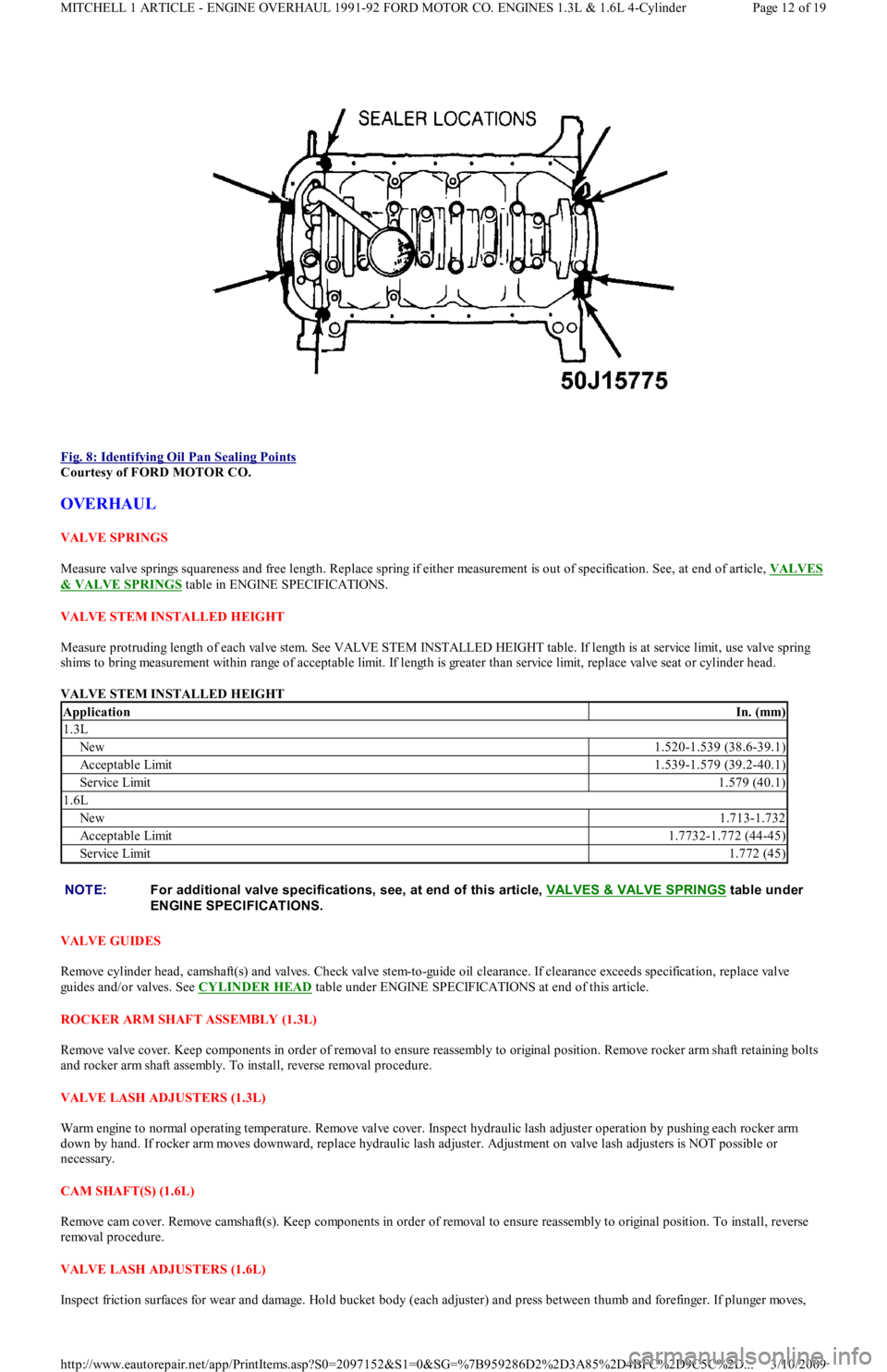
Fig. 8: Identifying Oil Pan Sealing Points
Courtesy of FORD MOTOR CO.
OVERHAUL
VALVE SPRINGS
Measure valve springs squareness and free length. Replace spring if either measurement is out of specification. See, at end of article, VALVES
& VALVE SPRINGS table in ENGINE SPECIFICATIONS.
VALVE STEM INSTALLED HEIGHT
Measure protruding length of each valve stem. See VALVE STEM INSTALLED HEIGHT table. If length is at service limit, use valve spring
shims to bring measurement within range of acceptable limit. If length is greater than service limit, replace valve seat or cylinder head.
VALVE STEM INSTALLED HEIGHT
VALVE GUIDES
Remove cylinder head, camshaft(s) and valves. Check valve stem-to-guide oil clearance. If clearance exceeds specification, replace valve
guides and/or valves. See CYLINDER HEAD
table under ENGINE SPECIFICATIONS at end of this article.
ROCKER ARM SHAFT ASSEMBLY (1.3L)
Remove valve cover. Keep components in order of removal to ensure reassembly to original position. Remove rocker arm shaft retaining bolts
and rocker arm shaft assembly. To install, reverse removal procedure.
VALVE LASH ADJUSTERS (1.3L)
Warm engine to normal operating temperature. Remove valve cover. Inspect hydraulic lash adjuster operation by pushing each rocker arm
down by hand. If rocker arm moves downward, replace hydraulic lash adjuster. Adjustment on valve lash adjusters is NOT possible or
necessary.
CAM SHAFT(S) (1.6L)
Remove cam cover. Remove camshaft(s). Keep components in order of removal to ensure reassembly to original position. To install, reverse
removal procedure.
VALVE LASH ADJUSTERS (1.6L)
Inspect friction surfaces for wear and damage. Hold bucket body (each adjuster) and press between thumb and forefinger. If plunge r mo ve s,
ApplicationIn. (mm)
1.3L
New1.520-1.539 (38.6-39.1)
Acceptable Limit1.539-1.579 (39.2-40.1)
Service Limit1.579 (40.1)
1.6L
New1.713-1.732
Acceptable Limit1.7732-1.772 (44-45)
Service Limit1.772 (45)
NOTE:For additional valve specifications, see, at end of this article, VALVES & VALVE SPRINGS
table under
ENGINE SPECIFICAT IONS.
Page 12 of 19 MITCHELL 1 ARTICLE - ENGINE OVERHAUL 1991-92 FORD MOTOR CO. ENGINES 1.3L & 1.6L 4-Cylinder
3/10/2009 http://www.eautorepair.net/app/PrintItems.asp?S0=2097152&S1=0&SG=%7B959286D2%2D3A85%2D4BFC%2D9C5C%2D
...
Page 114 of 454
2. Remove main bearing cap bolts. Remove cap and lower bearing insert. Use bearing remover or fabricated cotter key to remove upper
bearing insert. Insert bearing remover in journal lubrication hole. Rotate crankshaft in normal direction of operation only. Repeat
procedure for remaining main bearings.
3. Check bearings for abnormal wear. Check crankshaft for grooves, scratches and pitting. Using Plastigage method, check clearance of
main bearing-to-crankshaft. Always keep at least 2 bearings and caps tight during clearance check. See, at end of article,
CRANKSHAFT MAIN & CONNECTING ROD BEARINGS
table under ENGINE SPECIFICATIONS.
4. Lubricate and install new bearings in cap and block. Match bearing tangs with notch in cap and block. Position cap in its proper
location and position. Install cap bolts and tighten to specification. See TORQUE SPECIFICATIONS
table at end of article. Repeat
procedure for remaining main bearings.
CRANKSHAFT END PLAY
Check crankshaft end play with dial indicator. End play should be .0031-.0111" (.08-.282 mm). Service limit is .012" (.30 mm). If end play is
not within specification, replace thrust bearings as necessary.
CYLINDER BLOCK
1. Using straightedge and feeler gauge, check entire cylinder head surface of cylinder block. Ensure warpage does not exceed .006" (.15
mm). If warpage exceeds specification, cylinder block surface can be machined a maximum of .008" (.20 mm).
2. Replace cylinder block if it needs to be machined more than .008" (.20 mm). Check cylinder bore for wear, out-of-round, taper and
piston fit. See CYLINDER BORE SPECIFICATIONS
table. Oversize pistons are available in .010" and .020" (.25 mm and .50 mm).
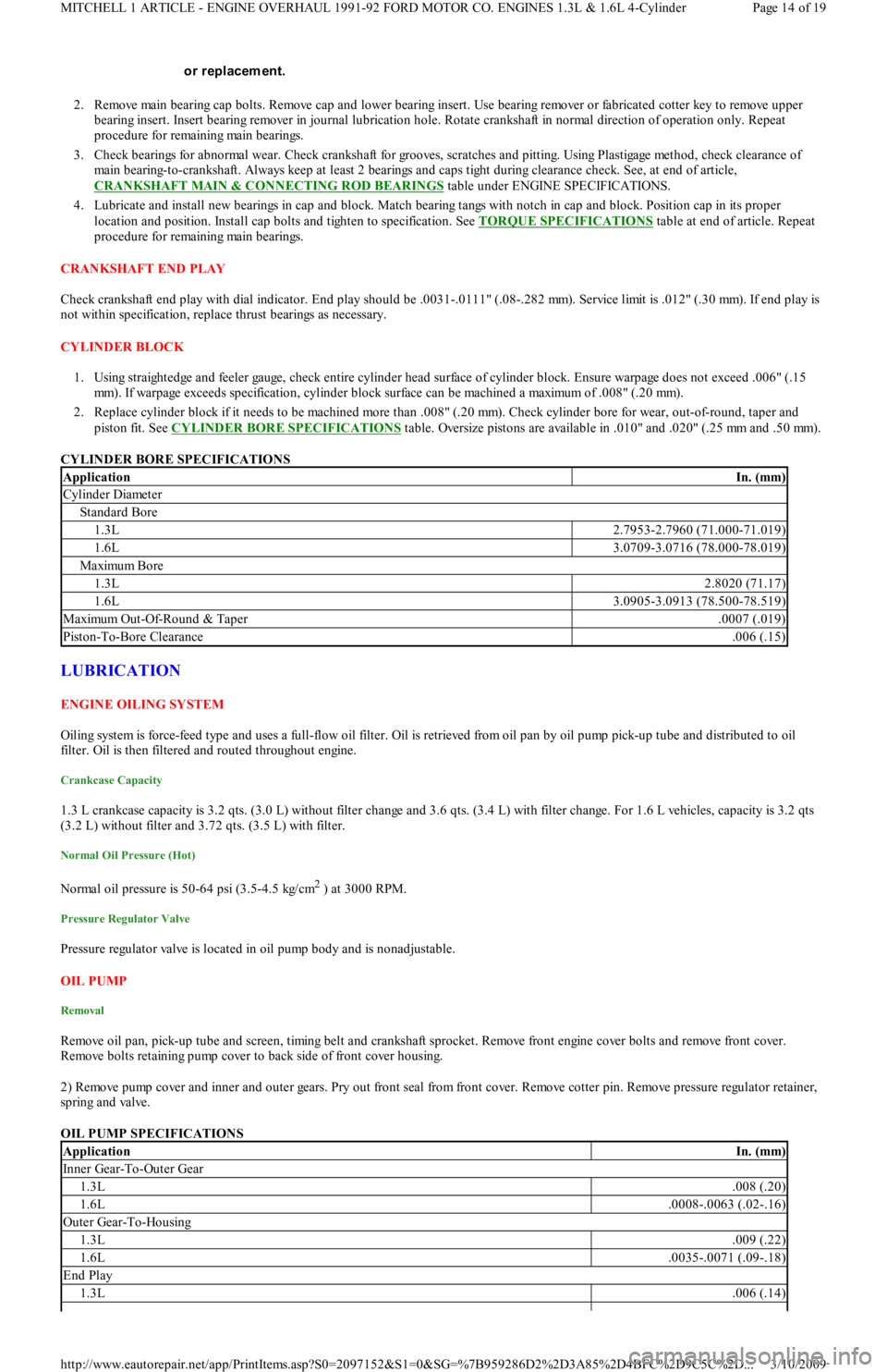
CYLINDER BORE SPECIFICATIONS
LUBRICATION
ENGINE OILING SYSTEM
Oiling system is force-feed type and uses a full-flow oil filter. Oil is retrieved from oil pan by oil pump pick-up tube and distributed to oil
filter. Oil is then filtered and routed throughout engine.
Crankcase Capacity
1.3 L crankcase capacity is 3.2 qts. (3.0 L) without filter change and 3.6 qts. (3.4 L) with filter change. For 1.6 L vehicles, capacity is 3.2 qts
(3.2 L) without filter and 3.72 qts. (3.5 L) with filter.
Normal Oil Pressure (Hot)
Normal oil pressure is 50-64 psi (3.5-4.5 kg/cm2 ) at 3000 RPM.
Pressure Regulator Valve
Pressure regulator valve is located in oil pump body and is nonadjustable.
OIL PUMP
Removal
Remove oil pan, pick-up tube and screen, timing belt and crankshaft sprocket. Remove front engine cover bolts and remove front cover.
R e mo ve b o l t s r e t a in in g p u mp c o ve r t o b a c k sid e o f fr o n t c o ve r h o u sin g.
2) Remove pump cover and inner and outer gears. Pry out front seal from front cover. Remove cotter pin. Remove pressure regulator retainer,
spring and valve.
OIL PUMP SPECIFICATIONS or replacem ent.
ApplicationIn. (mm)
Cylinder Diameter
Standard Bore
1.3L2.7953-2.7960 (71.000-71.019)
1.6L3.0709-3.0716 (78.000-78.019)
Maximu m Bo re
1.3L2.8020 (71.17)
1.6L3.0905-3.0913 (78.500-78.519)
Maximu m Ou t -Of-Ro u n d & Tap er.0007 (.019)
Piston-To-Bore Clearance.006 (.15)
ApplicationIn. (mm)
Inner Gear-To-Outer Gear
1.3L.008 (.20)
1.6L.0008-.0063 (.02-.16)
Outer Gear-To-Housing
1.3L.009 (.22)
1.6L.0035-.0071 (.09-.18)
End Play
1.3L.006 (.14)
Page 14 of 19 MITCHELL 1 ARTICLE - ENGINE OVERHAUL 1991-92 FORD MOTOR CO. ENGINES 1.3L & 1.6L 4-Cylinder
3/10/2009 http://www.eautorepair.net/app/PrintItems.asp?S0=2097152&S1=0&SG=%7B959286D2%2D3A85%2D4BFC%2D9C5C%2D
...
Page 115 of 454

Installation
1. Install pressure regulator valve, spring, retainer and new cotter pin. Press a new seal in front cover housing. Install outer and inner gears
in housing. Install pump cover. Coat bolts with Loctite and tighten to specification. See TORQUE SPECIFICATIONS
table at end of
article.
2. Install new gasket and install front cover housing. Install new gasket and install pick-up tube and screen. Tighten all bolts/nuts to
specification. To complete installation, reverse removal procedure.
ENGINE COOLING
TORQUE SPECIFICATIONS
TORQUE SPECIFICATIONS
1.6L.0012-.0043 (.03-.11)
NOTE:Refer to WAT ER PUMP
under REMOVAL & INSTALLATION in this article.
ApplicationFt. Lbs. (N.m)
"A" Arm Front Bolt72-86 (97-117)
A/C Compressor Bolt29-40 (39-54)
Camshaft Sprocket Bolt36-45 (49-61)
Connecting Rod Nut
Step 111-13 (15-18)
Step 2
1.3L22-25 (30-34)
1.6L35-38 (47-52)
Crankshaft Pulley Bolts9-13 (12-17)
Crankshaft Sprocket Bolt80-87 (108-118)
Crossmember-To-Body Bolt
1.3L47-66 (64-89)
1.6L27-37 (35-50)
Cylinder Head Bolt
Step 135-40 (48-54)
Step 256-60 (76-81)
Exhaust Manifold-To-Cylinder Head
1.3L12-17 (16-23)
1.6L29-42 (39-57)
Exhaust Pipe-To-Manifold29-42 (39-57)
Exhaust Pipe-To-Support Bracket32-45 (43-61)
Flywheel Bolt71-76 (96-103)
Front Cover Housing Bolt (1.3L)14-19 (19-26)
Front Engine Mount Nut32-38 (43-52)
Heater Tube32-45 (43-61)
Intake Manifold-To-Cylinder Head
1.3L14-20 (19-27)
1.6L47-66 (64-89)
Main Bearing Cap Bolts40-44 (54-59)
O2 Sensor27-33 (37-45)
Oil Pump Cover Bolt (1.6L)14-18 (19-25)
P/S Pump Bracket (Nut & Bolt)35-49 (47-66)
P/S Adjusting Nut27-38 (37-52)
P/S Pivot Bolt23-34 (31-46)
Pulse Air Tube Nut23-34 (31-46)
Rear Engine Mount Nut
1.3L21-34 (28-46)
1.6L47-66 (64-89)
Rocker Arm Shaft Bolts16-21 (22-28)
Side Engine Mount Nuts
1.3L29-40 (39-54)
1.6L
RH49-67 (67-91)
LH33-48 (45-65)
Spark Plug11-17 (15-23)
Thermostat Housing Bolt14-22 (19-30)
Timing Belt Tensioner Adjusting Bolt14-19 (19-26)
Turbo Oil Supply Tube
Engine Block Side12-18 (16-24)
Banjo Side(1) 106-159 (12-18)
Turbo-To-Manifold29-42 (39-57)
Water Outlet Bolt14-22 (19-30)
Water Pump Pulley Bolts (1.3L)36-45 (49-61)
Page 15 of 19 MITCHELL 1 ARTICLE - ENGINE OVERHAUL 1991-92 FORD MOTOR CO. ENGINES 1.3L & 1.6L 4-Cylinder
3/10/2009 http://www.eautorepair.net/app/PrintItems.asp?S0=2097152&S1=0&SG=%7B959286D2%2D3A85%2D4BFC%2D9C5C%2D
...
Page 116 of 454
ENGINE SPECIFICATIONS
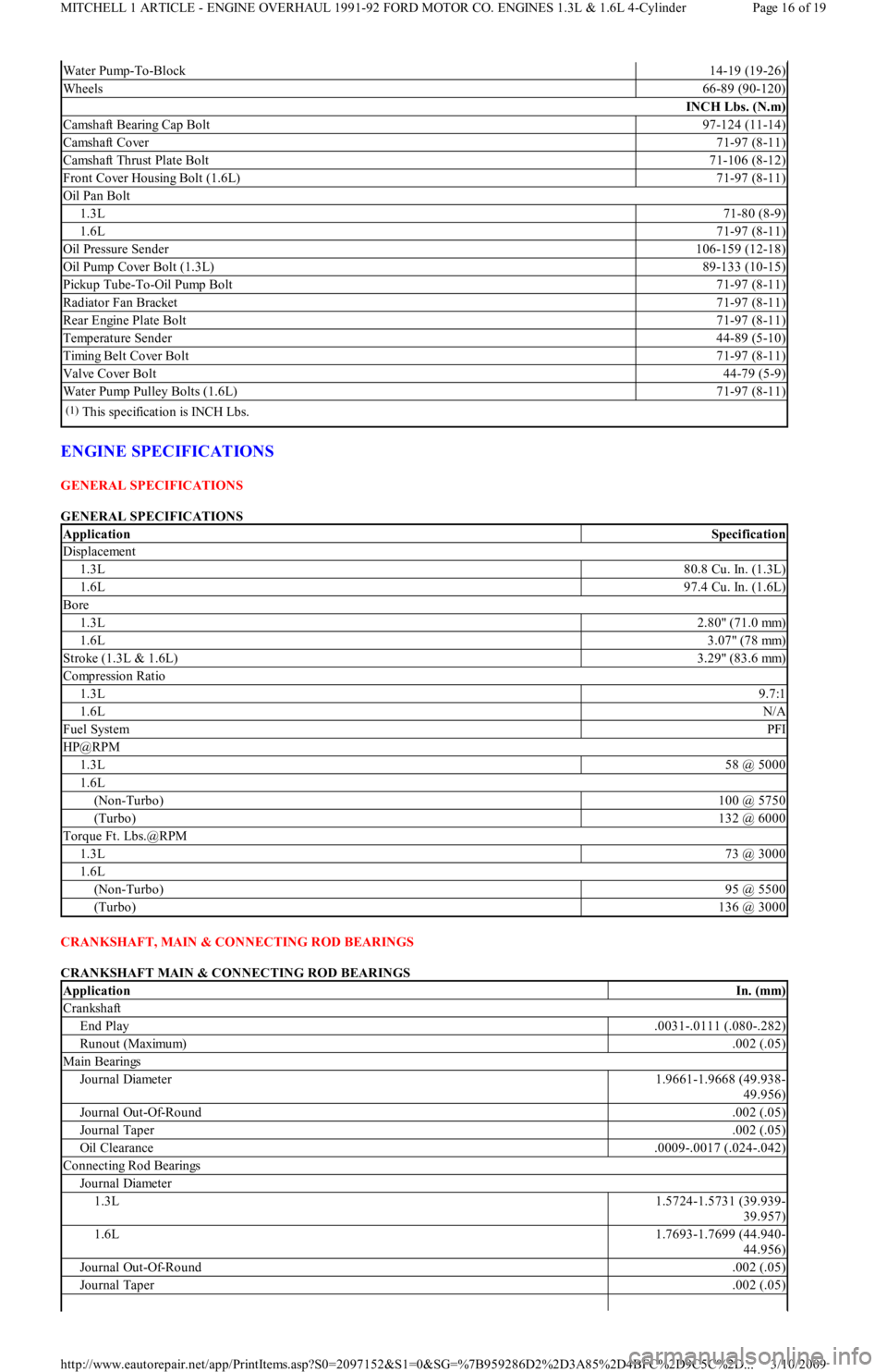
GENERAL SPECIFICATIONS
GENERAL SPECIFICATIONS
CRANKSHAFT, MAIN & CONNECTING ROD BEARINGS
CRANKSHAFT MAIN & CONNECTING ROD BEARINGS
Water Pump-To-Block14-19 (19-26)
Wheels66-89 (90-120)
INCH Lbs. (N.m)
Camshaft Bearing Cap Bolt97-124 (11-14)
Camshaft Cover71-97 (8-11)
Camshaft Thrust Plate Bolt71-106 (8-12)
Front Cover Housing Bolt (1.6L)71-97 (8-11)
Oil Pan Bolt
1.3L71-80 (8-9)
1.6L71-97 (8-11)
Oil Pressure Sender106-159 (12-18)
Oil Pump Cover Bolt (1.3L)89-133 (10-15)
Pickup Tube-To-Oil Pump Bolt71-97 (8-11)
Radiator Fan Bracket71-97 (8-11)
Rear Engine Plate Bolt71-97 (8-11)
Temperature Sender44-89 (5-10)
Timing Belt Cover Bolt71-97 (8-11)
Valve Cover Bolt44-79 (5-9)
Water Pump Pulley Bolts (1.6L)71-97 (8-11)
(1)This specification is INCH Lbs.
ApplicationSpecification
Displacement
1.3L80.8 Cu. In. (1.3L)
1.6L97.4 Cu. In. (1.6L)
Bore
1.3L2.80" (71.0 mm)
1.6L3.07" (78 mm)
Stroke (1.3L & 1.6L)3.29" (83.6 mm)
Compression Ratio
1.3L9.7:1
1.6LN/A
Fuel SystemPFI
HP@RPM
1.3L58 @ 5000
1.6L
(Non-Turbo)100 @ 5750
(Turbo)132 @ 6000
Torque Ft. Lbs.@RPM
1.3L73 @ 3000
1.6L
(Non-Turbo)95 @ 5500
(Turbo)136 @ 3000
ApplicationIn. (mm)
Crankshaft
End Play.0031-.0111 (.080-.282)
Runout (Maximum).002 (.05)
Main Bearings
Journal Diameter1.9661-1.9668 (49.938-
49.956)
Journal Out-Of-Round.002 (.05)
Journal Taper.002 (.05)
Oil Clearance.0009-.0017 (.024-.042)
Connecting Rod Bearings
Journal Diameter
1.3L1.5724-1.5731 (39.939-
39.957)
1.6L1.7693-1.7699 (44.940-
44.956)
Journal Out-Of-Round.002 (.05)
Journal Taper.002 (.05)
Page 16 of 19 MITCHELL 1 ARTICLE - ENGINE OVERHAUL 1991-92 FORD MOTOR CO. ENGINES 1.3L & 1.6L 4-Cylinder
3/10/2009 http://www.eautorepair.net/app/PrintItems.asp?S0=2097152&S1=0&SG=%7B959286D2%2D3A85%2D4BFC%2D9C5C%2D
...
Page 128 of 454
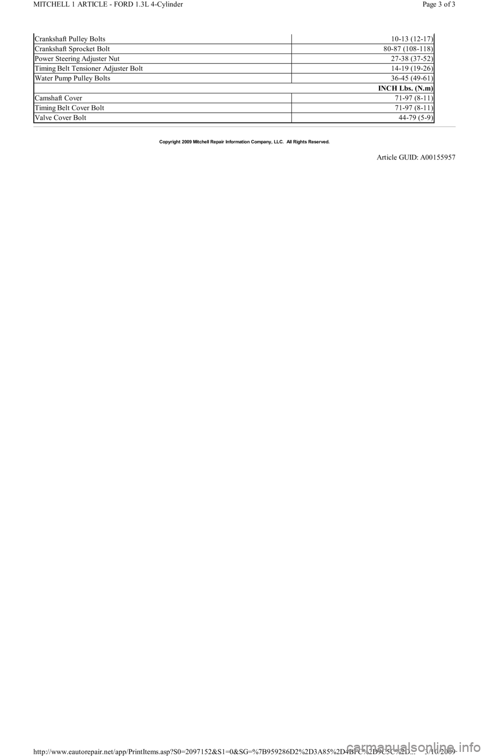
Crankshaft Pulley Bolts10-13 (12-17)
Crankshaft Sprocket Bolt80-87 (108-118)
Power Steering Adjuster Nut27-38 (37-52)
Timing Belt Tensioner Adjuster Bolt14-19 (19-26)
Water Pump Pulley Bolts36-45 (49-61)
INCH Lbs. (N.m)
Camshaft Cover71-97 (8-11)
Timing Belt Cover Bolt71-97 (8-11)
Valve Cover Bolt44-79 (5-9)
Copyr ight 2009 Mitchell Repair Information Company, LLC. All Rights Reserved.
Article GUID: A00155957
Page 3 of 3 MITCHELL 1 ARTICLE - FORD 1.3L 4-Cylinder
3/10/2009 http://www.eautorepair.net/app/PrintItems.asp?S0=2097152&S1=0&SG=%7B959286D2%2D3A85%2D4BFC%2D9C5C%2D
...
Page 139 of 454

EVAP-CPCV
EVAP Canister Purge Control Valve
EVAP-CPRV
EVAP Canister Purge Regulator Valve
EVAP-CPSV
EVAP Canister Vent Shut Valve
EVAP-CPT
EVAP Canister Purge Timer
EVAP-CPTVS
EVAP Canister Purge Thermal Vacuum Switch
EVAP-CPV
EVAP Canister Vent Valve
EVAP-CPVCSV
EVAP Canister Purge Volume Control
EVAP-CPVDV
EVAP Canister Purge Vacuum Delay Valve
EVAP-CS
EVAP Control Solenoid
EVAP-CSPS
EVAP Control System Pressure Sensor
EVAP-ORVR
Evaporative On-Board Refueling Vapor Recovery System
EVAP-ORVRFTVRV
EVAP-ORVR Fuel Tank Vapor Recirculation
EVAP-OVCV
EVAP Outer Vent Control Valve
EVAP-OW V
EVAP One-Way Valve
EVAP-PCSV
EVAP Purge Cut-Off Solenoid Valve
EVAP-PFS
EVAP Purge Flow Sensor
EVAP-PFSVVSV
EVAP Purge Flow Switching Valve Vacuum Switching Valve
EVAP-PRRV
EVAP Pressure Relief Rollover Valve
EVAP-VC
EVAP Vapor Canister
FF
Flexible Fuel
Page 7 of 9 MITCHELL 1 ARTICLE - EMISSION CONTROL APPLICATIONS Emission Applications - Ford Motor Co. - Imports (1968-
...
3/10/2009 http://www.eautorepair.net/app/PrintItems.asp?S0=2097152&S1=0&SG=%7B7DD6473C%2DB5BB%2D4F20%2D9D70%2D
...