1991 FORD FESTIVA wheel
[x] Cancel search: wheelPage 32 of 454

lock nut. Discard axle lock nut. Separate tie rod end from knuckle.
2. Disconnect brake hose from strut (if necessary). Remove brake caliper assembly from knuckle and wire out of way. Remove nuts and
bolts holding ball joint and strut to knuckle assembly.
3. Remove knuckle assembly from ball joint and drive shaft. If binding occurs, use a dual-jawed puller to force knuckle/hub/rotor assembly
off drive axle shaft.
4. Using a puller, separate knuckle from wheel hub. Retain original outer bearing preload spacer to maintain bearing preload setting. If
replacing bearing, change spacer to maintain proper bearing preload (if necessary). See FRONT WHEEL BEARINGS under REMOVAL
& INSTALLATION. Scribe match marks between hub and rotor assembly. Remove rotor-to-hub bolts. Separate hub from rotor.
Installation
Align marks and install rotor on hub. Press knuckle and preload spacer into wheel hub assembly. To complete installation, reverse removal
procedure. Tighten axle shaft lock nut to 117-175 ft. lbs. (159-237 N.m).
REAR BRAKE CALIPER & PADS
Removal (Capri)
1. Raise and support vehicle. Remove tire and wheel assembly. Using needle-nose pliers, remove parking brake return spring. Loosen
parking brake cable housing adjusting nut. Remove cable housing from bracket on lower control arm. Loosen parking brake cable
bracket-to-caliper attaching bolt. Remove parking brake cable from caliper.
2. Remove lower caliper retaining bolt. Pivot caliper upward on upper caliper guide pin. Remove brake pad retaining spring, pads and
shims. If replacing rear brake pads only, reverse removal procedure to install. If removing caliper, proceed to next step.
3. Remove attaching clip from brake flex hose. Remove flex hose banjo bolt from caliper and discard copper washers. Remove lower
caliper retaining bolt. Using a cold chisel, remove upper caliper guide pin dust cap. Using an Allen wrench, remove upper caliper guide
pin. Lift caliper off rotor.
Installation
1. To install, fit brake pads and shims into caliper anchor plate. Remove upper guide pin and lower guide pin bushing from caliper.
Remove guide pin and guide pin bushing dust boots. Lubricate upper guide pin and lower guide pin bushing with Disc Brake Caliper
Slide Grease (D7AZ-19590-A).
2. To complete installation, reverse removal procedure. To fit caliper over new brake pads, it may be necessary to rotate caliper piston into
caliper bore. Use NEW copper washers on flex hose. Bleed brakes, and then pump brake pedal several times to seat pads.
REAR BRAKE ROTOR
Removal & Installation (Capri)
See REAR WHEEL BEARINGS under REMOVAL & INSTALLATION.
REAR BRAKE SHOES
Removal & Installation (Festiva)
Remove brake drum. Remove hold-down springs. Remove return springs. Remove self adjuster. See Fig. 8 . To install, reverse removal
procedure. Apply brake grease to all shoe contact points. See REAR BRAKE SHOES under ADJUSTMENTS.
REAR WHEEL CYLINDER
Removal & Installation (Festiva)
Remove rear brake shoes. Disconnect brake line from wheel cylinder. Remove wheel cylinder. To install, reverse removal procedure. Bleed
brake system.
MASTER BRAKE CYLINDER
Removal
Disconnect low fluid level sensor wiring (if equipped). Drain some brake fluid from reservoir. Disconnect brake lines from master cylinder.
Cap lines and master cylinder ports. Remove attaching nuts and master cylinder.
Installation
To install, reverse removal procedure. Fill master cylinder to proper level and bleed hydraulic system (if necessary).
POWER BRAKE UNIT
Removal & Installation
Remove master cylinder. Disconnect vacuum line. Remove clevis pin at brake pedal. Remove power brake unit. To install, reverse removal
procedure.
FRONT WHEEL BEARINGS NOTE:Hub and rotor are a m atched and balanced assem bly. Before rem oving rotor, locate paint or etch
m ark indicating proper hub-to-rotor alignm ent. If m arks are not present, m ark hub and rotor for
assem bly alignm ent. Failure to properly align hub and rotor can result in an im balance condition.
Page 5 of 12 MITCHELL 1 ARTICLE - BRAKE SYSTEM 1991-92 BRAKES Disc & Drum
3/10/2009 http://www.eautorepair.net/app/PrintItems.asp?S0=2097152&S1=0&SG=%7B7DD6473C%2DB5BB%2D4F20%2D9D70%2D
...
Page 33 of 454
Removal
Remove rotor and hub assembly from steering knuckle. Separate rotor, knuckle and hub. See FRONT BRAKE ROTOR & HUB under
REMOVAL & INSTALLATION. Press outer bearing from hub using Bearing Splitter (D84L-1123-A) and Shaft Protector (D80L-625-2).
Remove and discard outer grease seal. Pry inner wheel bearing grease seal from steering knuckle using a large screwdriver. Discard seal.
R e mo ve in n e r b e a r in g.
Bearing Preload
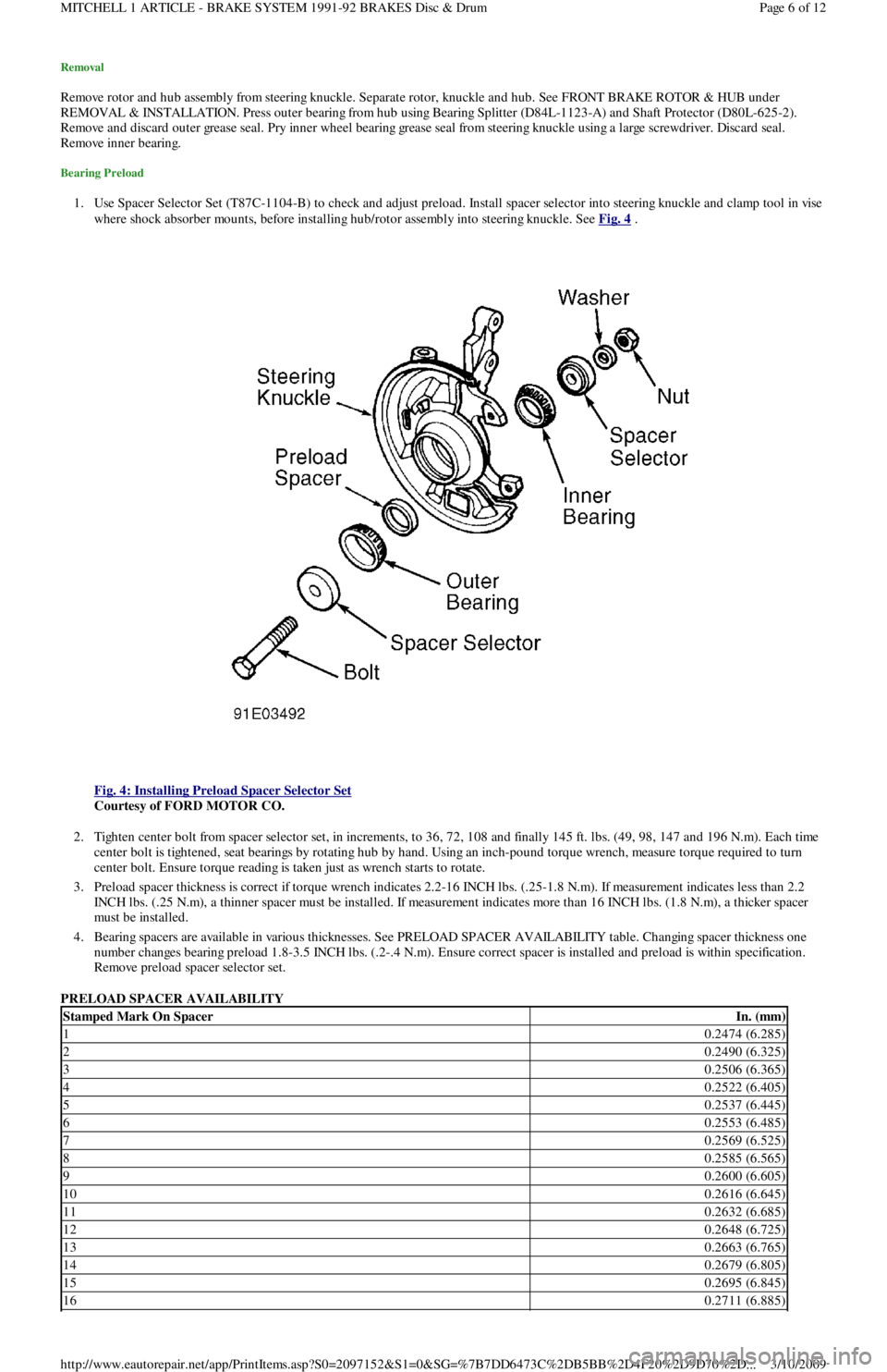
1. Use Spacer Selector Set (T87C-1104-B) to check and adjust preload. Install spacer selector into steering knuckle and clamp tool in vise
where shock absorber mounts, before installing hub/rotor assembly into steering knuckle. See Fig. 4
.
Fig. 4: Installing Preload Spacer Selector Set
Courtesy of FORD MOTOR CO.
2. Tighten center bolt from spacer selector set, in increments, to 36, 72, 108 and finally 145 ft. lbs. (49, 98, 147 and 196 N.m). Each time
center bolt is tightened, seat bearings by rotating hub by hand. Using an inch-pound torque wrench, measure torque required to turn
center bolt. Ensure torque reading is taken just as wrench starts to rotate.
3. Preload spacer thickness is correct if torque wrench indicates 2.2-16 INCH lbs. (.25-1.8 N.m). If measurement indicates less than 2.2
INCH lbs. (.25 N.m), a thinner spacer must be installed. If measurement indicates more than 16 INCH lbs. (1.8 N.m), a thicker spacer
must be installed.
4. Bearing spacers are available in various thicknesses. See PRELOAD SPACER AVAILABILITY table. Changing spacer thickness one
number changes bearing preload 1.8-3.5 INCH lbs. (.2-.4 N.m). Ensure correct spacer is installed and preload is within specification.
Remove preload spacer selector set.
PRELOAD SPACER AVAILABILITY
Stamped Mark On SpacerIn. (mm)
10.2474 (6.285)
20.2490 (6.325)
30.2506 (6.365)
40.2522 (6.405)
50.2537 (6.445)
60.2553 (6.485)
70.2569 (6.525)
80.2585 (6.565)
90.2600 (6.605)
100.2616 (6.645)
110.2632 (6.685)
120.2648 (6.725)
130.2663 (6.765)
140.2679 (6.805)
150.2695 (6.845)
160.2711 (6.885)
Page 6 of 12 MITCHELL 1 ARTICLE - BRAKE SYSTEM 1991-92 BRAKES Disc & Drum
3/10/2009 http://www.eautorepair.net/app/PrintItems.asp?S0=2097152&S1=0&SG=%7B7DD6473C%2DB5BB%2D4F20%2D9D70%2D
...
Page 34 of 454
Installation
1. Lubricate bearings with appropriate wheel bearing grease. Place inner bearing into steering knuckle. Install new inner bearing gr e a se
seal, and drive seal into place using appropriate seal installer.
2. Place original outer wheel bearing preload spacer (or spacer selected during preload inspection process) into steering knuckle bore.
Place outer wheel bearing into steering knuckle bore.
3. Liberally lubricate lip of NEW outer grease seal with appropriate lubricant. Drive seal into steering knuckle bore. Install brake rotor on
hub axle hub. Tighten bolts to 33-40 ft. lbs. (45-54 N.m). Position rotor/hub assembly into steering knuckle, and press assembly into
place using adapter from spacer selector set. To complete installation, reverse removal procedure.
REAR WHEEL BEARINGS
Removal & Installation
1. Raise and support rear axle. Remove wheel. Remove wheel bearing dust cap. On Capri, remove rear brake caliper. See REAR BRAKE
CALIPER & PADS under REMOVAL & INSTALLATION. On all models, carefully unstake rear axle lock nut using a chisel. DO NOT
damage threads on axle spindle. Remove and discard axle nut.
2. On Capri, remove rotor/hub assembly. On Festiva, remove brake drum/hub assembly. On all models, DO NOT allow outer wheel
bearing to fall out of hub. Remove inner bearing grease seal. Remove inner bearing. To install rear bearings, reverse removal procedure.
Adjust rear wheel bearings. See REAR AXLE BEARINGS under ADJUSTMENTS.
OVERHAUL
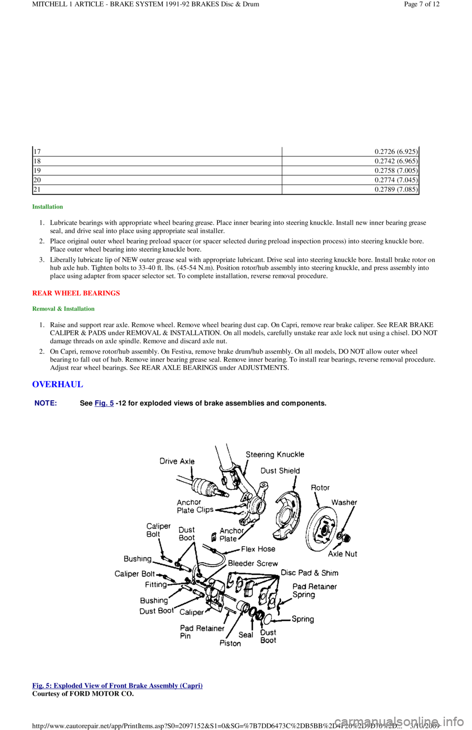
Fig. 5: Exploded View of Front Brake Assembly (Capri)
Courtesy of FORD MOTOR CO.
170.2726 (6.925)
180.2742 (6.965)
190.2758 (7.005)
200.2774 (7.045)
210.2789 (7.085)
NOTE:See Fig. 5
-12 for exploded views of brake assem blies and com ponents.
Page 7 of 12 MITCHELL 1 ARTICLE - BRAKE SYSTEM 1991-92 BRAKES Disc & Drum
3/10/2009 http://www.eautorepair.net/app/PrintItems.asp?S0=2097152&S1=0&SG=%7B7DD6473C%2DB5BB%2D4F20%2D9D70%2D
...
Page 36 of 454
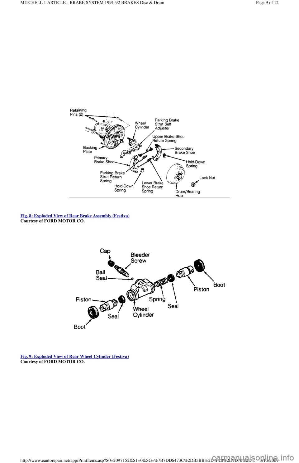
Fig. 8: Exploded View of Rear Brake Assembly (Festiva)
Courtesy of FORD MOTOR CO.
Fig. 9: Exploded View of Rear Wheel Cylinder (Festiva)
Courtesy of FORD MOTOR CO.
Page 9 of 12 MITCHELL 1 ARTICLE - BRAKE SYSTEM 1991-92 BRAKES Disc & Drum
3/10/2009 http://www.eautorepair.net/app/PrintItems.asp?S0=2097152&S1=0&SG=%7B7DD6473C%2DB5BB%2D4F20%2D9D70%2D
...
Page 38 of 454
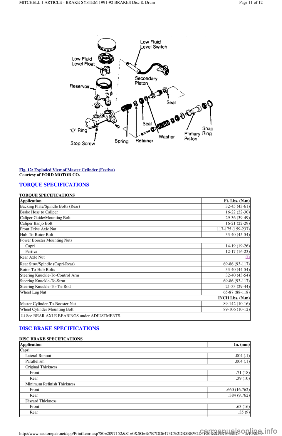
Fig. 12: Exploded View of Master Cylinder (Festiva)
Courtesy of FORD MOTOR CO.
TORQUE SPECIFICATIONS
TORQUE SPECIFICATIONS
DISC BRAKE SPECIFICATIONS
DISC BRAKE SPECIFICATIONS
ApplicationFt. Lbs. (N.m)
Backing Plate/Spindle Bolts (Rear)32-45 (43-61)
Brake Hose to Caliper16-22 (22-30)
Caliper Guide/Mounting Bolt29-36 (39-49)
Caliper Banjo Bolt16-21 (22-29)
Front Drive Axle Nut117-175 (159-237)
Hub-To-Rotor Bolt33-40 (45-54)
Power Booster Mounting Nuts
Capri14-19 (19-26)
Festiva12-17 (16-23)
Rear Axle Nut(1)
Rear Strut/Spindle (Capri-Rear)69-86 (93-117)
Rotor-To-Hub Bolts33-40 (44-54)
Steering Knuckle-To-Control Arm32-40 (43-54)
Steering Knuckle-To-Strut69-86 (93-117)
Steering Knuckle-To-Tie Rod21-33 (29-44)
Wheel Lug Nut65-87 (88-118)
INCH Lbs. (N.m)
Master Cylinder-To-Booster Nut89-142 (10-16)
Wheel Cylinder Mounting Bolt89-106 (10-12)
(1)See REAR AXLE BEARINGS under ADJUSTMENTS.
ApplicationIn. (mm)
Capri
Lateral Runout.004 (.1)
Parallelism.004 (.1)
Original Thickness
Front.71 (18)
Rear.39 (10)
Min imu m Refin ish Th ickn ess
Front.660 (16.762)
Rear.384 (9.762)
Discard Thickness
Front.63 (16)
Rear.35 (9)
Page 11 of 12 MITCHELL 1 ARTICLE - BRAKE SYSTEM 1991-92 BRAKES Disc & Drum
3/10/2009 http://www.eautorepair.net/app/PrintItems.asp?S0=2097152&S1=0&SG=%7B7DD6473C%2DB5BB%2D4F20%2D9D70%2D
...
Page 40 of 454
Back To Article
AXLE SHAFT S - FRONT
1988-93 Drive Axles - FWD Axle Shafts
DESCRIPTION & OPERATION
Axle shafts transfer power from transaxle to driving wheels. All axle shafts consist of a shaft with a flexible Constant Velocity (CV) joint at
each end. Inner CV joint is coupled to transaxle by splines. Outer CV joint is splined to hub assembly and secured by axle shaft nut.
Three different types of axle shaft CV joints are used: Double Offset Joint (DOJ) or Rzeppa type, Birfield Joint (BJ) and the Tripot Joint (TJ).
CV joint boots protect CV joints by maintaining proper lubrication and preventing contaminants from entering joint. Boots must be replaced
when signs of leakage or cracks are present. Inner CV joint may be disassembled and serviced. Outer CV joint boot may be replaced, but outer
Birfield CV joint must NOT be disassembled. It must be replaced as an assembly, if faulty.
To prevent torsional vibration and torque steer on turbocharged Capri vehicles, an intermediate shaft and conventional axle shaft are used on
the right side. Both shafts are of similar length and are supported by a bearing, which is attached to engine.
CV JOINT IDENTIFICATION
TROUBLE SHOOTING
REMOVAL, DISASSEMBLY, REASSEMBLY & INSTALLATION
FWD AXLE SHAFTS
Removal
1. Raise and support vehicle. Remove lower underbody splash shields. Drain transaxle fluid. Remove front wheels and loosen axle shaft
lock nut. On Capri, remove stabilizer bar-to-control arm attaching nuts, bolt, washers and bushings. On Festiva, remove stabilizer bar
attaching nuts and bracket. On all models, remove joint clamp bolt from lower control arm. Pry downward and separate steering knuckle
from ball joint, taking care not to damage ball joint dust boot.
2. On Capri turbo, remove bolts securing intermediate shaft bearing bracket to engine. On all models, slowly pry axle shaft from transaxle
using a flat-tip screwdriver or pry bar. Axle is held into transaxle by a circlip fitted to the end of the axle. Remove axle shaft from wheel
hub. If difficult to remove, use axle puller to remove axle from drive hub. Remove axle shaft from transaxle. Plug transaxle openings
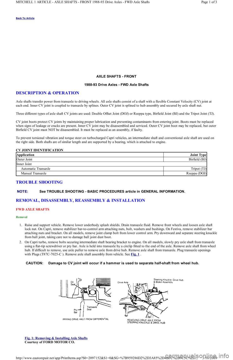
with Plugs (T87C-7025-C ). Remove axle shaft assembly from vehicle. See Fig. 1
.
Fig. 1: Removing & Installing Axle Shafts
Courtesy of FORD MOTOR CO.
ApplicationJoint Type
Outer JointBirfield (BJ)
In n er Jo in t
Automatic TransaxleTripot (TJ)
Manual TransaxleRzeppa (DOJ)
NOTE:See TROUBLE SHOOTING - BASIC PROCEDURES article in GENERAL INFORMATION.
CAUTION: Dam age to CV joint will occur if a ham mer is used to separate half-shaft from wheel hub.
Page 1 of 3 MITCHELL 1 ARTICLE - AXLE SHAFTS - FRONT 1988-93 Drive Axles - FWD Axle Shafts
3/10/2009 http://www.eautorepair.net/app/PrintItems.asp?S0=2097152&S1=0&SG=%7B959286D2%2D3A85%2D4BFC%2D9C5C%2D
...
Page 42 of 454
Installation (All)
1. To install axle shaft, reverse removal procedure. Always install a NEW retaining circlip. Check seals at both ends of axle shaft. If
necessary, replace seals prior to installation. Lubricate transaxle seal lip with transaxle oil. See Fig. 1
.
2. After installing axle shaft into transaxle, pull axle shaft outward by hand to ensure proper engagement of retaining circlip and snap ring.
Install axle shaft into wheel hub. Align suspension alignment marks and tighten nuts.
INTERMEDIATE SHAFT
Removal
Intermediate shaft and axle shaft are removed as an assembly. See FWD AXLE SHAFTS under REMOVAL, DISASSEMBLY,
REASSEMBLY & INSTALLATION.
Disassembly
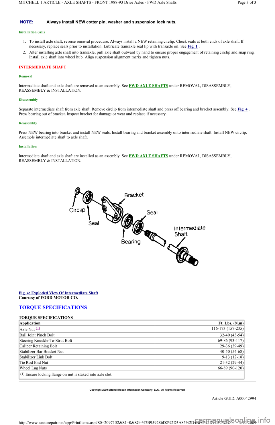
Separate intermediate shaft from axle shaft. Remove circlip from intermediate shaft and press off bearing and bracket assembly. See Fig. 4 .
Press bearing out of bracket. Inspect bracket for damage or wear and replace if necessary.
Reassembly
Press NEW bearing into bracket and install NEW seals. Install bearing and bracket assembly onto intermediate shaft. Install NEW circlip.
Assemble intermediate shaft to axle shaft.
Installation
Intermediate shaft and axle shaft are installed as an assembly. See FWD AXLE SHAFTS under REMOVAL, DISASSEMBLY,
REASSEMBLY & INSTALLATION.
Fig. 4: Exploded View Of Intermediate Shaft
Courtesy of FORD MOTOR CO.
TORQUE SPECIFICATIONS
TORQUE SPECIFICATIONS NOTE:Always install NEW cotter pin, washer and suspension lock nuts.
ApplicationFt. Lbs. (N.m)
Axle Nut (1) 116-173 (157-235)
Ball Joint Pinch Bolt32-40 (43-54)
Steering Knuckle-To-Strut Bolt69-86 (93-117)
Caliper Retaining Bolt29-36 (39-49)
Stabilizer Bar Bracket Nut40-50 (54-68)
Stabilizer Link Bolt9-13 (12-18)
Tie Rod End Nut21-32 (29-44)
Wheel Lug Nuts66-89 (90-120)
(1)Ensure locking flange on nut is staked into axle slot.
Copyr ight 2009 Mitchell Repair Information Company, LLC. All Rights Reserved.
Article GUID: A00042994
Page 3 of 3 MITCHELL 1 ARTICLE - AXLE SHAFTS - FRONT 1988-93 Drive Axles - FWD Axle Shafts
3/10/2009 http://www.eautorepair.net/app/PrintItems.asp?S0=2097152&S1=0&SG=%7B959286D2%2D3A85%2D4BFC%2D9C5C%2D
...
Page 52 of 454
Back To Article
ST ART ER
1991 ELECT RICAL Starters
DESCRIPTION
The Nippondenso direct drive starter is a conventional 12-volt, 4-pole, brush-type starter. The integral solenoid is attached to the drive
housing. When starter is energized, starter solenoid causes the starter pinion to engage with the flywheel ring gear. The overrunning clutch
pinion drive is mounted directly on armature shaft drive end.
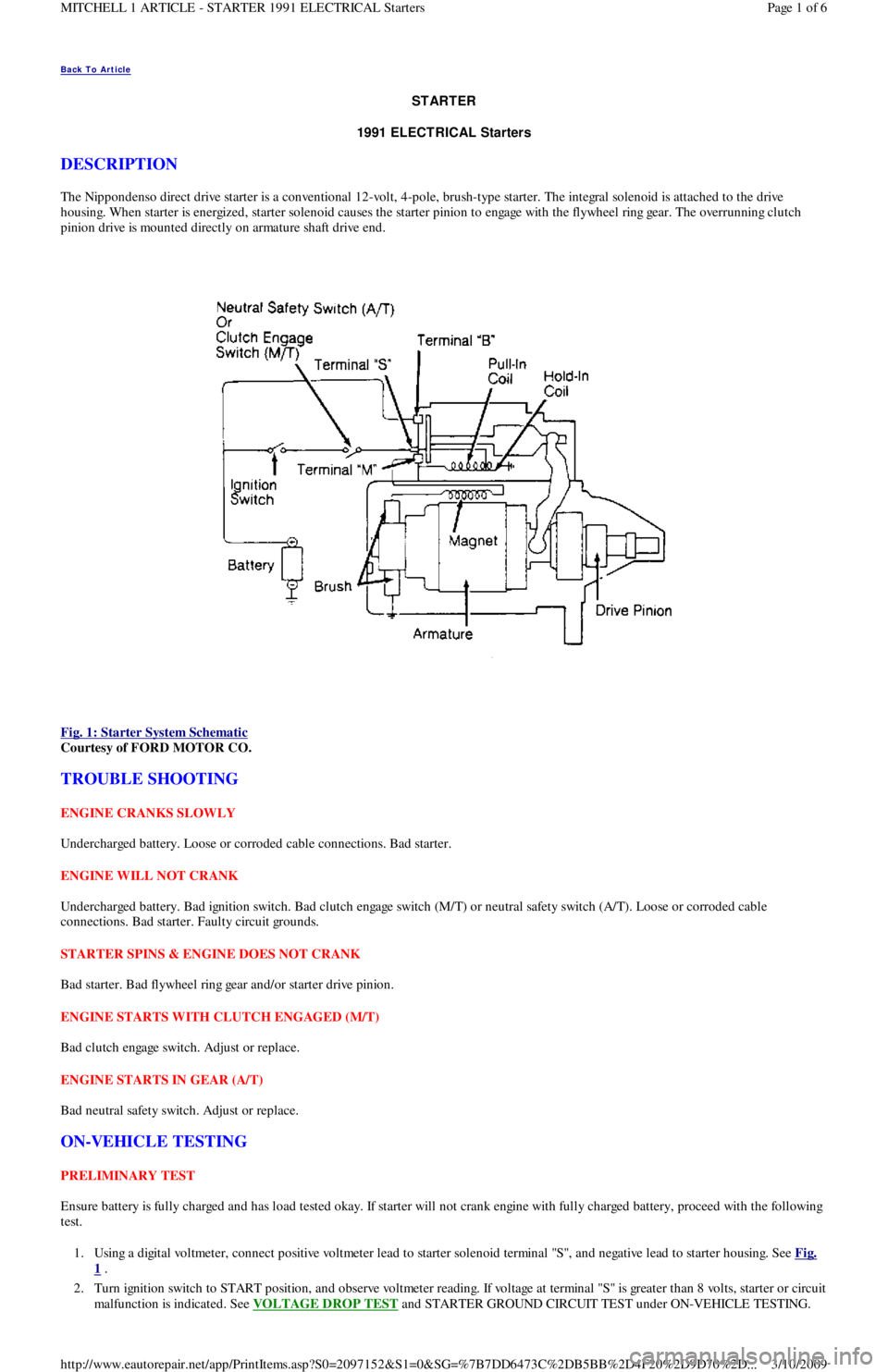
Fig. 1: Starter System Schematic
Courtesy of FORD MOTOR CO.
TROUBLE SHOOTING
ENGINE CRANKS SLOWLY
Undercharged battery. Loose or corroded cable connections. Bad starter.
ENGINE WILL NOT CRANK
Undercharged battery. Bad ignition switch. Bad clutch engage switch (M/T) or neutral safety switch (A/T). Loose or corroded cable
connections. Bad starter. Faulty circuit grounds.
STARTER SPINS & ENGINE DOES NOT CRANK
Bad starter. Bad flywheel ring gear and/or starter drive pinion.
ENGINE STARTS WITH CLUTCH ENGAGED (M/T)
Bad clutch engage switch. Adjust or replace.
ENGINE STARTS IN GEAR (A/T)
Bad neutral safety switch. Adjust or replace.
ON-VEHICLE TESTING
PRELIMINARY TEST
Ensure battery is fully charged and has load tested okay. If starter will not crank engine with fully charged battery, proceed with the following
test.
1. Using a digital voltmeter, connect positive voltmeter lead to starter solenoid terminal "S", and negative lead to starter housing. See Fig.
1 .
2. Turn ignition switch to START position, and observe voltmeter reading. If voltage at terminal "S" is greater than 8 volts, starter or circuit
malfunction is indicated. See VOLTAGE DROP TEST
and STARTER GROUND CIRCUIT TEST under ON-VEHICLE TESTING.
Page 1 of 6 MITCHELL 1 ARTICLE - STARTER 1991 ELECTRICAL Starters
3/10/2009 http://www.eautorepair.net/app/PrintItems.asp?S0=2097152&S1=0&SG=%7B7DD6473C%2DB5BB%2D4F20%2D9D70%2D
...