Page 381 of 1640
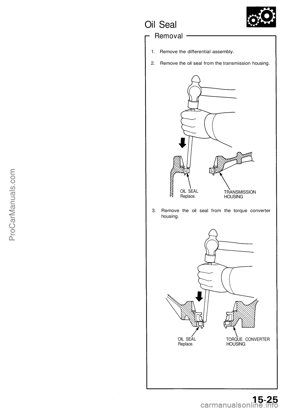
Oil Seal
Removal
1. Remove the differential assembly.
2. Remove the oil seal from the transmission housing.
OIL SEAL
Replace.
TRANSMISSION
HOUSING
3. Remove the oil seal from the torque converter
housing.
OIL SEAL
Replace.
TORQUE CONVERTER
HOUSINGProCarManuals.com
Page 382 of 1640
Bearing Preload
Adjustment
NOTE: If any of the items listed below are replaced, the
bearing preload must be adjusted.
TRANSMISSION HOUSING
TORQUE CONVERTER HOUSING
DIFFERENTIAL
TAPERED ROLLER BEARING and OUTER RACE
75 mm THRUST SHIM
90 mm WASHER
OIL GUIDE RING
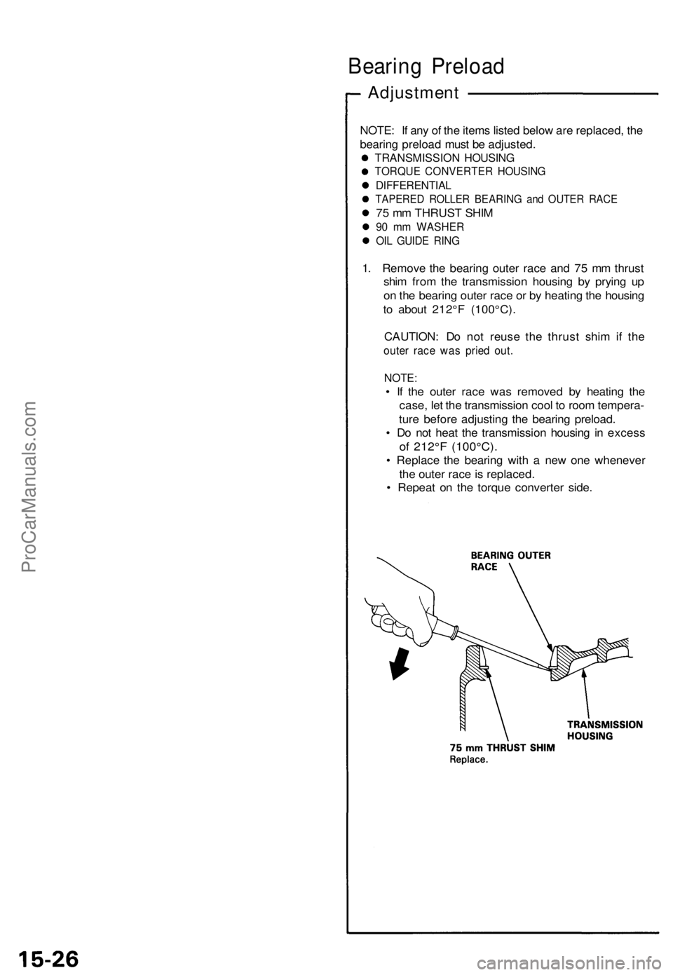
1. Remove the bearing outer race and 75 mm thrust
shim from the transmission housing by prying up
on the bearing outer race or by heating the housing
to about 212°F (100°C).
CAUTION: Do not reuse the thrust shim if the
outer race was pried out.
NOTE:
• If the outer race was removed by heating the
case, let the transmission cool to room tempera-
ture before adjusting the bearing preload.
• Do not heat the transmission housing in excess
of 212°F (100°C).
• Replace the bearing with a new one whenever
the outer race is replaced.
• Repeat on the torque converter side.ProCarManuals.com
Page 407 of 1640
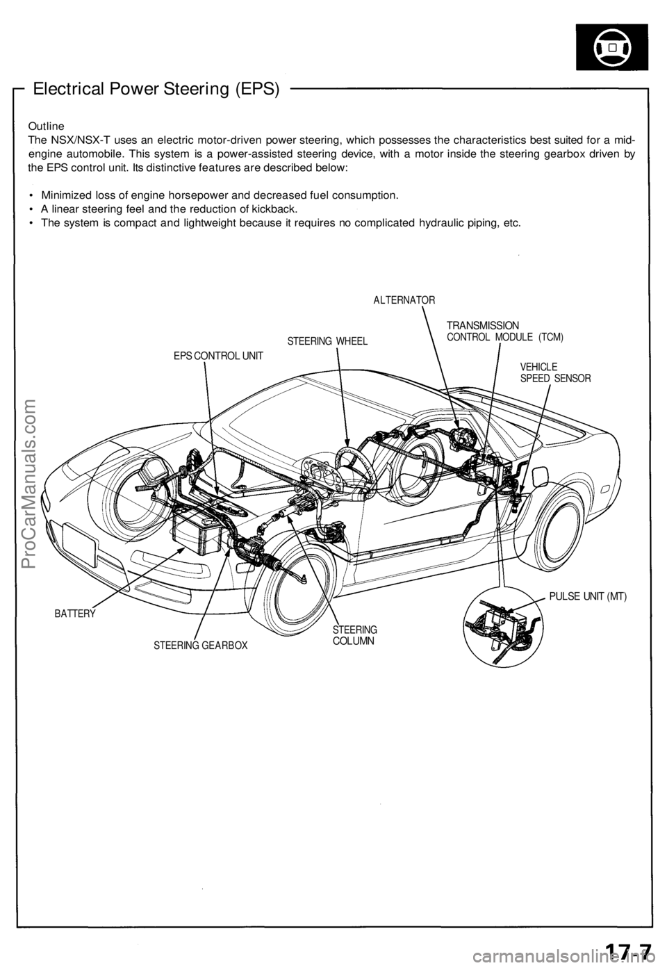
Electrical Power Steering (EPS)
Outline
The NSX/NSX-T uses an electric motor-driven power steering, which possesses the characteristics best suited for a mid-
engine automobile. This system is a power-assisted steering device, with a motor inside the steering gearbox driven by
the EPS control unit. Its distinctive features are described below:
• Minimized loss of engine horsepower and decreased fuel consumption.
• A linear steering feel and the reduction of kickback.
• The system is compact and lightweight because it requires no complicated hydraulic piping, etc.
ALTERNATOR
TRANSMISSION
CONTROL MODULE (TCM)
EPS CONTROL UNIT
VEHICLE
SPEED SENSOR
PULSE UNIT (MT)
BATTERY
STEERING GEARBOX
STEERING WHEEL
STEERING
COLUMNProCarManuals.com
Page 408 of 1640
System Description
Major Components
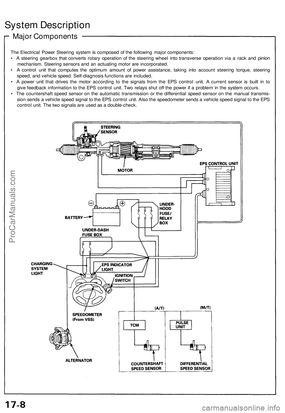
The Electrical Power Steering system is composed of the following major components:
• A steering gearbox that converts rotary operation of the steering wheel into transverse operation via a rack and pinion
mechanism. Steering sensors and an actuating motor are incorporated.
• A control unit that computes the optimum amount of power assistance, taking into account steering torque, steering
speed, and vehicle speed. Self-diagnosis functions are included.
• A power unit that drives the motor according to the signals from the EPS control unit. A current sensor is built in to
give feedback information to the EPS control unit. Two relays shut off the power if a problem in the system occurs.
• The countershaft speed sensor on the automatic transmission or the differential speed sensor on the manual transmis-
sion sends a vehicle speed signal to the EPS control unit. Also the speedometer sends a vehicle speed signal to the EPS
control unit. The two signals are used as a double-check.ProCarManuals.com
Page 411 of 1640
Rotation Sensor
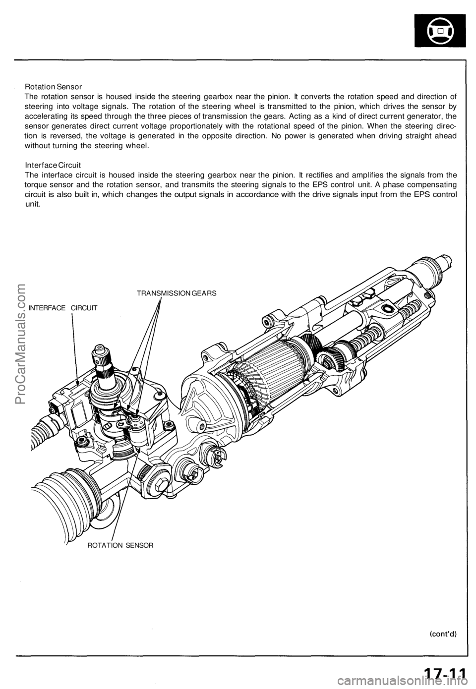
The rotation sensor is housed inside the steering gearbox near the pinion. It converts the rotation speed and direction of
steering into voltage signals. The rotation of the steering wheel is transmitted to the pinion, which drives the sensor by
accelerating its speed through the three pieces of transmission the gears. Acting as a kind of direct current generator, the
sensor generates direct current voltage proportionately with the rotational speed of the pinion. When the steering direc-
tion is reversed, the voltage is generated in the opposite direction. No power is generated when driving straight ahead
without turning the steering wheel.
Interface Circuit
The interface circuit is housed inside the steering gearbox near the pinion. It rectifies and amplifies the signals from the
torque sensor and the rotation sensor, and transmits the steering signals to the EPS control unit. A phase compensating
circuit is also built in, which changes the output signals in accordance with the drive signals input from the EPS control
unit.
TRANSMISSION GEARS
INTERFACE CIRCUIT
ROTATION SENSORProCarManuals.com
Page 558 of 1640
Steering angle sensor system check
1. Start the engine,
2. Push the TCS switch three times within three seconds.
NOTE: Always maintain the same number of rota-
tions.
3. Turn the steering wheel slowly from left to right more than 1.5 turns.
NOTE:
Start checking after the steering wheel moves at
least 1.5 turns from right to left.
Turn the steering wheel slowly, no faster than
one turn in four seconds.
4. Push the TCS switch twice within three seconds. NOTE: Always maintain the same number of rota-
tions.
5. Return the steering wheel to the left side slowly, and check the number of times the TCS indicator light
flashes after the wheel has moved approximately
one turn.
NOTE:
Start the check from the beginning when the steer-ing wheel moves at least one turn from left to
right, Turn the steering wheel slowly, no faster than one
turn in four seconds.
Standard number of times the TCS indicator light
flashes:
Manual Transmission: 5 times
Automatic Transmission: 2 times
6. If there is an abnormality, check the troubleshooting flowchart (see page 19-98('91-'93)('94-'96)
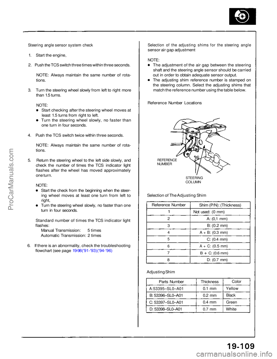
Selection of the adjusting shims for the steering angle
sensor air gap adjustment
NOTE:
The adjustment of the air gap between the steeringshaft and the steering angle sensor should be carried
out in order to obtain adequate sensor output.
The adjusting shim reference number is stamped on
the steering column. Select the adjusting shims that match the reference number using the table below.
Reference Number Locations
REFERENCE
NUMBER
STEERING
COLUMN
Selection of The Adjusting Shim
Adjusting Shim Parts Number
A:53395–SL0–A01
B: 53396–SL0–A01
C: 53397–SL0–A01
D: 53398–SL0–A01
Thickness
0.1 mm
0.2 mm
0.4 mm
0.7 mm
Color
Yellow
Black
Green
White
Reference Number
1
2
3
4
5
6
7
8
Shim (P/N): (Thickness)
Not used: (0 mm)
A:
(0,1
mm)
B:
(0.2
mm)
A + B:
(0.3
mm)
C:
(0.4
mm)
A + C:
(0.5
mm)
B + C:
(0.6
mm)
D:
(0.7
mm)ProCarManuals.com
Page 735 of 1640
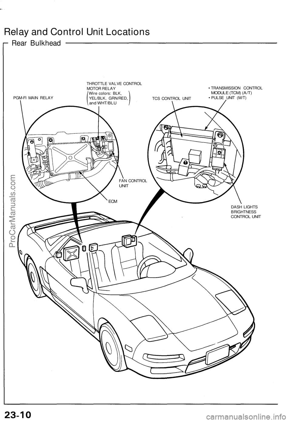
Relay and Control Unit Locations
Rear Bulkhead
PGM-FI MAIN RELAY
THROTTLE VALVE CONTROL
MOTOR RELAY
Wire colors: BLK,
YEL/BLK, GRN/RED,
and WHT/BLU
TCS CONTROL UNIT
TRANSMISSION CONTROL
MODULE (TCM) (A/T)
PULSE UNIT (M/T)
DASH LIGHTS
BRIGHTNESS
CONTROL UNIT
FAN CONTROL
UNIT
ECMProCarManuals.com
Page 749 of 1640
- I f th e starte r stil l doe s no t cran k th e engine ,
remov e th e starte r an d diagnos e it s interna l
problems .
- I f th e starte r crank s th e engine , chec k fo r a n
ope n i n th e BLK/WH T wir e an d connector s be -
twee n th e starte r an d ignitio n switch . Chec k th e
ignitio n switch .
On car s wit h automati c transmission , chec k th e
A/ T gea r positio n switc h (neutra l positio n
switch ) an d connector .
O n car s with manua l transmission , chec k th e
starte r cu t relay , clutc h interloc k switc h an d
connectors .
NOTE : Chec k th e No . 2 9 (5 0 A ) fus e an d th e
starte r cu t relay , an d inspec t th e securit y alar m
system .
3 . Chec k fo r wea r o r damage :
Th e starte r shoul d cran k th e engin e smoothl y an d
steadily .
If th e starte r engages , bu t crank s th e engin e er -
ratically , remov e th e starte r motor . Inspec t th e
starter , driv e gea r an d flywhee l rin g gea r fo r
damage .
Check th e driv e gea r overrunnin g clutc h fo r bindin g
or slippin g whe n th e armatur e i s rotated with th e
driv e gea r held . Replac e th e gear s i f damaged .
4 . Chec k crankin g voltag e an d curren t draw :
Voltag e shoul d b e n o les s tha n 8. 5 volts .
Curren t shoul d b e n o mor e tha n 35 0 amperes .
I f voltag e i s to o low , o r curren t dra w to o high ,
chec k for :
• Lo w battery .
• Ope n circui t i n starte r armatur e commutato r
segments .
• Starte r armatur e dragging .
• Shorte d armatur e winding .
• Excessiv e dra g i n engine . 5
. Chec k crankin g rpm :
Engin e spee d durin g crankin g shoul d b e abov e 10 0
rpm .
If spee d i s to o low , chec k for :
Loos e batter y o r starte r terminals .
Excessivel y wor n starte r brushes .
Ope n circui t i n commutato r segments .
Dirt y o r damage d helica l splin e o r driv e gear .
Defectiv e driv e gea r overrunnin g clutch .
6 . Chec k th e starte r disengagement :
Depres s th e clutc h peda l al l th e wa y (M/T ) o r shif t
to positio n (A/T) , tur n th e ignitio n switc h
to "Star t (III) " an d releas e to O N (II) .
The starter drive gea r shoul d disengag e fro m th e
flywhee l rin g gear .
I f th e driv e gea r hang s u p o n th e flywhee l rin g gear ,
check :
• Solenoi d plunge r an d switc h fo r malfunction .
• Driv e gea r assembl y fo r dir t o r damage d over -
runnin g clutch .
ProCarManuals.com