Page 935 of 1640

Cruise Control
Description
The cruise control system uses mechanically and electri-
cally operated devices to maintain vehicle speed at a
setting selected by the driver.
The ECM receives command signals from the cruise con-
trol main switch and the cruise control set/resume switch.
It receives information about operating conditions from
the brake switch, vehicle speed sensor (VSS), the clutch
switch (with manual transmission), or the A/T gear posi-
tion switch (with automatic transmission). The ECM
sends operational signals to the devices that regulate the
throttle position. The throttle position maintains the
selected vehicle speed. Essentially, the ECM compares
the actual speed of the vehicle to the selected speed.
Then, it uses the result of that comparison to open or
close the throttle.
The brake switch releases the system's control of the
throttle at the instant the driver depresses the brake
pedal. The switch sends an electronic signal to the ECM
when the brake pedal is depressed; the ECM responds
by allowing the throttle to close. The clutch switch (man-
ual transmission) or the A/T gear position switch (auto-
matic transmission) sends a disengage signal to the
ECM that also allows the throttle to close.
Operation:
The cruise control system will set and automatically
maintain any speed above 25 mph (45 km/h). To set,
make sure that the main switch is in the "ON" position.
After reaching the desired speed, press the set switch.
The ECM will receive a set signal and, in turn, will actu-
ate the throttle valve control motor. When the set switch
is depressed and the cruise control system is on, the
"cruise control" ON indicator in the gauge assembly will
light up. You can cancel the cruise control system by
pushing the main switch to "OFF". This erases the set
speed from memory. If the system is disengaged tem-
porarily by the brake switch, clutch switch, or A/T gear
position switch and vehicle speed is still above 25 mph,
press the resume switch. With the resume switch
depressed and the set memory retained, the vehicle
automatically returns to the previous set speed.
For gradual acceleration without depressing the acceler-
ator pedal, push the resume switch down and hold it
there until the desired speed is reached. This will send
an acceleration signal to the ECM. When the switch is
released, the system will be reprogrammed for the new
speed. To slow down, depress the set switch. This will
send a deceleration signal to the ECM causing the car to
coast until the desired speed is reached. When the
desired speed is reached, release the set switch. This
will reprogram the system for the new speed.ProCarManuals.com
Page 960 of 1640
Warning/Caution Label Locations
SRS CAUTION LABELS: Refer to page 1-8.
FROZEN
BATTERY CAUTION
BATTERY
CAUTION
RADIATOR BLEED
PLUG CAUTION
AIR CONDITIONING
R-134a CAUTION (U.S.A only)
EXPANSION
TANK CAP
CAUTION
ENGINE COOLANT CAUTION PRECAUTION
SPARK PLUG
CAUTION
TIRE INFORMATION
ABS CAUTION
ABS and BRAKE
FLUID CAUTION
RETRACTABLE
HEADLIGHT CAUTION
EMISSION CONTROL
INFORMATION and
VACUUM HOSE
ROUTING DIAGRAM
(cont'd)ProCarManuals.com
Page 969 of 1640
Warning/Caution Label Locations
SRS CAUTION LABELS: Refer to page 1-8.
FROZEN
BATTERY CAUTION
BATTERY
CAUTION
RADIATOR BLEED
PLUG CAUTION
AIR CONDITIONING R-134a CAUTION(U.S.A only)
EXPANSION
TANK CAP CAUTION
ENGINE COOLANT
CAUTION • PRECAUTION
SPARK PLUG
CAUTION
TIRE INFORMATION
EMISSION CONTROL
INFORMATION and
VACUUM HOSE
ROUTING DIAGRAM
RETRACTABLE
HEADLIGHT CAUTION
ABS and BRAKE
FLUID CAUTION ABS CAUTION
(cont'd)ProCarManuals.com
Page 973 of 1640

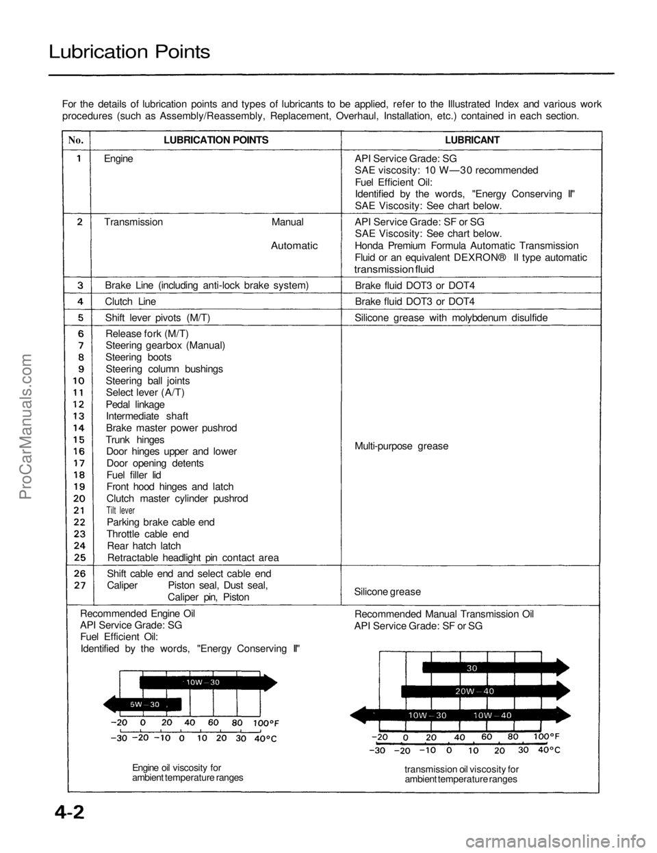
Lubrication Points
For the details of lubrication points and types of lubricants to be applied, refer to the Illustrated Index and various workprocedures (such as Assembly/Reassembly, Replacement, Overhaul, Installation, etc.) contained in each section.
No.
LUBRICATION POINTS
LUBRICANT
Engine
Transmission
Manual
Automatic
Brake Line (including anti-lock brake system)
Clutch Line Shift lever pivots (M/T)Release fork (M/T)Steering gearbox (Manual)
Steering boots Steering column bushings
Steering ball jointsSelect lever (A/T)
Pedal linkage Intermediate shaft
Brake master power pushrod
Trunk hinges Door hinges upper and lower
Door opening detents
Fuel filler lid
Front hood hinges and latch
Clutch master cylinder pushrod
Tilt lever
Parking brake cable end
Throttle cable end Rear hatch latchRetractable headlight pin contact area
Shift cable end and select cable end
Caliper Piston seal, Dust seal, Caliper pin, Piston
Recommended Engine Oil
API Service Grade: SG Fuel Efficient Oil:
Identified by the words, "Energy Conserving II" API Service Grade: SG
SAE viscosity: 10 W—30 recommended
Fuel Efficient Oil:
Identified by the words, "Energy Conserving II"
SAE Viscosity: See chart below.
API Service Grade: SF or SG SAE Viscosity: See chart below.
Honda Premium Formula Automatic Transmission
Fluid or an equivalent DEXRON® II type automatic
transmission fluid
Brake fluid DOT3 or DOT4
Brake fluid DOT3 or DOT4
Silicone grease with molybdenum disulfide
Multi-purpose grease
Silicone grease Recommended Manual Transmission Oil
API Service Grade: SF or SG
transmission oil viscosity forambient temperature ranges
Engine oil viscosity for
ambient temperature rangesProCarManuals.com
Page 1106 of 1640

Idle Control System
Idle Speed Setting
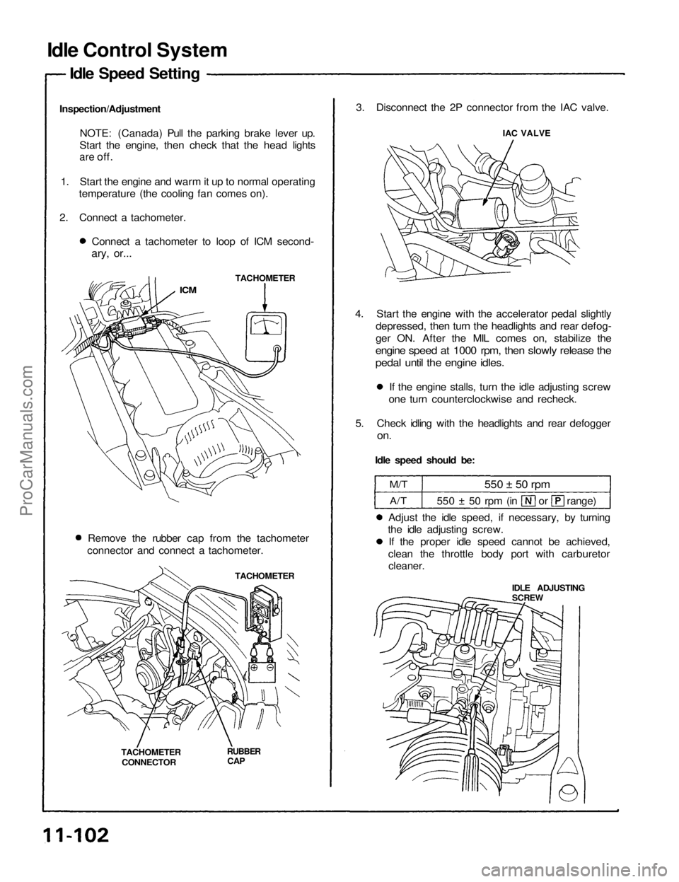
Inspection/Adjustment NOTE: (Canada) Pull the parking brake lever up.
Start the engine, then check that the head lights
are
off.
1. Start the engine and warm it up to normal operating temperature (the cooling fan comes on).
2. Connect a tachometer. Connect a tachometer to loop of ICM second-
ary, or...
TACHOMETER
ICM
Remove the rubber cap from the tachometer
connector and connect a tachometer.
TACHOMETER
TACHOMETER CONNECTOR
RUBBER
CAP
3. Disconnect the 2P connector from the IAC valve.
IAC VALVE
4. Start the engine with the accelerator pedal slightly depressed, then turn the headlights and rear defog-
ger ON. After the MIL comes on, stabilize the
engine speed at 1000 rpm, then slowly release the
pedal until the engine idles.
If the engine stalls, turn the idle adjusting screw
one turn counterclockwise and recheck.
5. Check idling with the headlights and rear defogger
on.
Idle speed should be:
M/T
A/T
550 ± 50 rpm
550 ± 50 rpm (in or range)
Adjust the idle speed, if necessary, by turning
the idle adjusting screw.
If the proper idle speed cannot be achieved,
clean the throttle body port with carburetor
cleaner.
IDLE ADJUSTING
SCREWProCarManuals.com
Page 1352 of 1640

Front Suspension
Hub Replacement
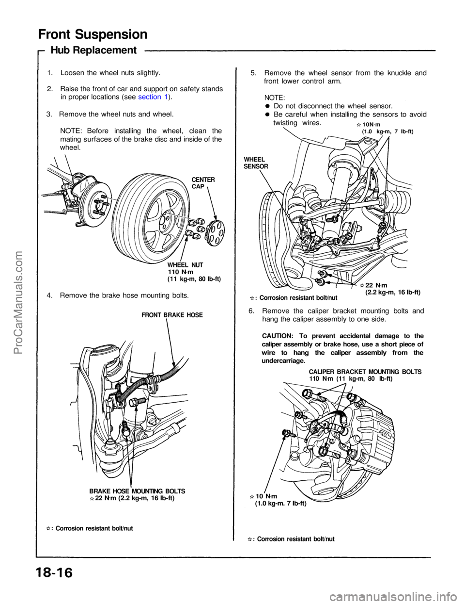
1. Loosen the wheel nuts slightly.
2. Raise the front of car and support on safety stands in proper locations (see section 1).
3. Remove the wheel nuts and wheel. NOTE: Before installing the wheel, clean the
mating surfaces of the brake disc and inside of the
wheel.
CENTER
CAP
WHEEL NUT
110 N .
m
(11 kg-m, 80 lb-ft)
4. Remove the brake hose mounting bolts.
FRONT BRAKE HOSE
BRAKE HOSE MOUNTING BOLTS
Corrosion resistant bolt/nut
5. Remove the wheel sensor from the knuckle and
front lower control arm.
Do not disconnect the wheel sensor.
Be careful when installing the sensors to avoid
twisting wires. 10N.
m
(1.0 kg-m, 7 lb-ft)
WHEEL
SENSOR
22 N.
m
(2.2 kg-m, 16 Ib-ft)
Corrosion resistant bolt/nut
6. Remove the caliper bracket mounting bolts and hang the caliper assembly to one side.
CAUTION: To prevent accidental damage to the
caliper assembly or brake hose, use a short piece of
wire to hang the caliper assembly from the
undercarriage.
CALIPER BRACKET MOUNTING BOLTS
110 N .
m (11 kg-m, 80 Ib-ft)
10 N .
m
(1.0 kg-m. 7 Ib-ft)
Corrosion resistant bolt/nut
22 N
.
m (2.2 kg-m, 16 Ib-ft)
NOTE:ProCarManuals.com
Page 1400 of 1640
Gauge Assembly
Bulb Locations
SRS INDICATOR LIGHT (1.4W)
EPS INDICATOR LIGHT (1.4 W)
RIGHT TURN SIGNAL INDICATOR LIGHT (1.4 W)
BRAKE SYSTEM LIGHT (1.4W)
SEAT BELT REMINDER LIGHT (1.4W)
TCS-OFF INDICATOR
LIGHT (1.96 W)
LOW FUEL INDICATOR
LIGHT (1.4W)
GAUGE LIGHT
(1.4W)
GAUGE LIGHT
(3.0W)
CRUISE LIGHT
(1.96W)
GAUGE LIGHT
(3.0W)
TCS ACTIVATION
INDICATOR LIGHT
(1.96
W)
GAUGE LIGHT
(3.0W)
GAUGE LIGHT
(1.4W)
LOW OIL PRESSURE
INDICATOR
,LIGHT(1.4W)
MALFUNCTION
INDICATOR
LAMP (MIL)
(1.4W)
CHARGING SYSTEM LIGHT (1.4 W)
ABS
INDICATOR LIGHT (1.4 W)
LEFT TURN SIGNAL INDICATOR LIGHT (1.4 W)
TCS INDICATOR LIGHT (1.4W)
HIGH BEAM INDICATOR LIGHT (1.4W)
GAUGE LIGHTS (1.4W x 2)ProCarManuals.com
Page 1404 of 1640
Blown No. 5 (10 A) fuse
(In the under-dash fuse box)
Blown No. 34 (15 A) fuse
(In the under-dash fuse box)
Safety indicator input
Safety indicator (Diodes)Brake light failure sensorDoor switch
Trunk latch switch
Retractable headlight control unit
(see page 23-174)
Poor ground
Open circuit, loose or disconnected
terminalsProCarManuals.com