Page 1586 of 1640

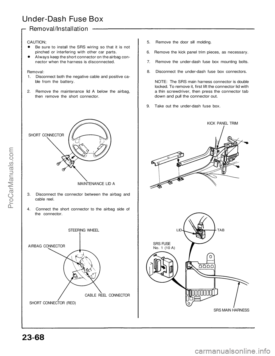
Under-Dash Fuse Box
Removal/Installation
CAUTION;
Be sure to install the SRS wiring so that it is not
pinched or interfering with other car parts.
Always keep the short connector on the airbag con-
nector when the harness is disconnected.
Removal:
1. Disconnect both the negative cable and positive ca-
ble from the battery.
2. Remove the maintenance lid A below the airbag,
then remove the short connector.
SHORT CONNECTOR
MAINTENANCE LID A
3. Disconnect the connector between the airbag and
cable reel.
4. Connect the short connector to the airbag side of
the connector.
STEERING WHEEL
AIRBAG CONNECTOR
CABLE REEL CONNECTOR
SHORT CONNECTOR (RED)
5. Remove the door sill molding.
6. Remove the kick panel trim pieces, as necessary.
7. Remove the under-dash fuse box mounting bolts.
8. Disconnect the under-dash fuse box connectors.
NOTE: The SRS main harness connector is double
locked. To remove it, first lift the connector lid with
a thin screwdriver, then press the connector tab
down and pull the connector out.
9. Take out the under-dash fuse box.
TAB
SRS FUSE
No. 1 (10 A)
SRS MAIN HARNESS
KICK PANEL TRIM
LIDProCarManuals.com
Page 1587 of 1640
Installation:
1. Install the under-dash fuse box.
KICK PANEL TRIM
2. Connect the connectors to the under-dash fuse box.
NOTE: To reinstall the SRS main harness connector,
push it into position until it clicks, then close the con-
nector lid.
3. Install the kick panel trim pieces.
4. Disconnect the short connector from the airbag.
SHORT
CONNECTOR
(RED)
MAINTENANCE
LID A
CABLE REEL
CONNECTOR
AIRBAG CONNECTOR
SHORT CONNECTOR
5. Connect the airbag 2-P connector and cable reel 2-P
connector.
6. Attach the short connector to the lid A and attach
to the steering wheel.
7. Connect both the negative cable and positive cable
to the battery.
8. After installing the under-dash fuse box, confirm that
all systems work properly.ProCarManuals.com
Page 1593 of 1640

— Defective gauge assemble, check for the A21
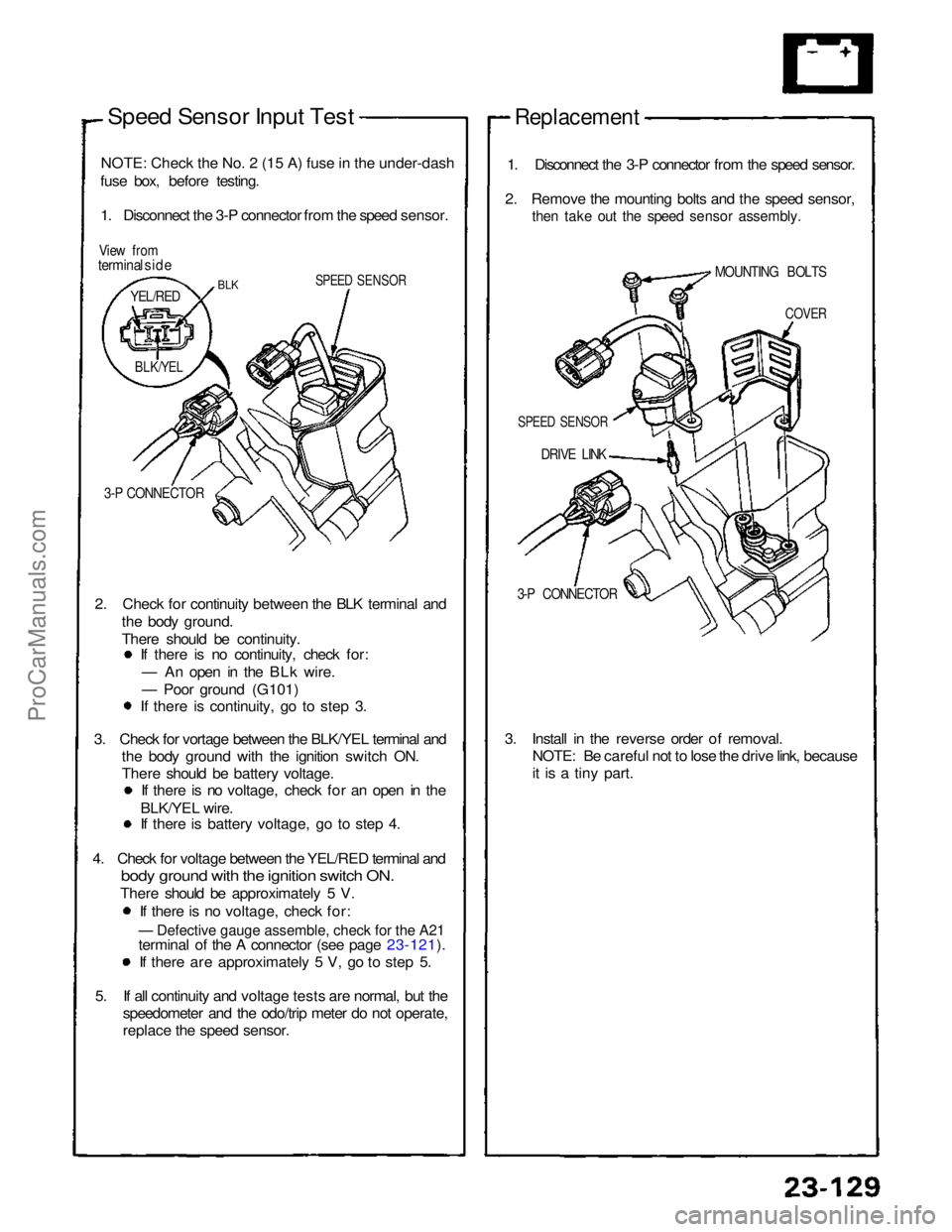
Speed Sensor Input Test
NOTE
:
Check the No. 2 (15 A) fuse in the under-dash
fuse box, before testing.
1. Disconnect the 3-P connector from the speed sensor.
View from
terminal side
SPEED SENSOR
3-P CONNECTOR
2. Check for continuity between the BLK terminal and the body ground.
There should be continuity. If there is no continuity, check for:
— An open in the BLk wire.
— Poor ground (G101) If there is continuity, go to step 3.
3. Check for vortage between the BLK/YEL terminal and the body ground with the ignition switch ON.
There should be battery voltage. If there is no voltage, check for an open in the
BLK/YEL wire. If there is battery voltage, go to step 4.
4. Check for voltage between the YEL/RED terminal and
bod
y
ground with the ignition switch ON.
There should be approximately 5 V.
If there is no voltage, check for:
terminal of the A connector (see page 23-121). If there are approximately 5 V, go to step 5.
5. If all continuity and voltage tests are normal, but the speedometer and the odo/trip meter do not operate,
replace the speed sensor.
Replacement
1. Disconnect the 3-P connector from the speed sensor.
2. Remove the mounting bolts and the speed sensor,
then take out the speed sensor assembly.
DRIVE LINK
3-P CONNECTOR
3. Install in the reverse order of removal. NOTE: Be careful not to lose the drive link, because
it is a tiny part.
BLK
YEL/RED
BLK/YEL
SPEED SENSOR
COVER
MOUNTING BOLTSProCarManuals.com
Page 1600 of 1640
Integrated Control Unit
Input Test
CAUTION: All SRS electrical wiring harnesses are covered with
yellow outer insulation.Before disconnecting the SRS wire harness, install
the short connector on the airbag (see page 23-323). Replace the entire affected SRS harness assembly
if it has an open circuit or damaged wiring.
Remove the left side kick panel cover, and the dash re-
lay holder from the bracket, to disconnect the 16-P con-
nector from the integrated control unit.
Remove the integrated control unit from the dash fuse box.
Make the following input tests at the connector ter-
manals. If all tests prove OK, yet the system still falls
to work, replace the control unit.
NOTE: Several different wires have the same color. They
have been given a number suffix to distinguish them (for
example YEL and YEL are not the same).
SRS MAIN WIRE HARNESS
INTEGRATED
CONTROL UNIT
16-P CONNECTOR
UNDER-DASH FUSE BOX Not used
View from wire sideProCarManuals.com
Page 1610 of 1640
Glove Box Light
Replacement/Test
1. Remove the glove box lower panel.
2. Remove the 8 screws then pull out the glove box.
3. Disconnect the 2-P connectors then remove the
glove box.
GLOVE BOX LOWER
PANEL
4. Remove the 2 screws from the glove box light.
GLOVE BOX
LIGHT
BULB (3.4W)
5. There should be continuity between the A terminal
and B terminal with a bulb installed. There should
be no continuity when the switch is pushed.
From FUSE
No.38 (15 A)
GLOVE BOX
LID
To GROUND
(401, G402)ProCarManuals.com
Page 1618 of 1640
CAUTION:
All SRS electrical wiring harnesses are covered with
yellow outer insulation.
Before disconnecting the SRS wire harness, install
the short connector on the airbag (see page 23-323). Replace the entire affected SRS harness assembly
if it has an open circuit or damaged wiring.
SRS MAIN WIRE HARNESS
DEFOGGER SWITCH
Removal, page 23-273
Test, page 23-275
REAR WINDOW DEFOGGER
Function Test, page 23-288
UNDER-DASH FUSE BOX
INTEGRATED
CONTROL UNIT
DEFOGGER
RELAY
ENGINE COMPARTMENT FUSE/RELAY BOX
Description Function:
The rear window defogger is controlled by the integrated control unit.
When the defogger switch in the combination switch is pushed, it sends a signal to the defogger timer in the integrated
contro
l
unit and the defogger stays on for 25 minutes or until the ignition swi\
tch is switched off.
The indicator light in the switch shows when the defogger is on.
Rear Window Defogger
Component
Location Index
ProCarManuals.com
Page 1626 of 1640
Troubleshooting
NOTE:
The numbers in the table show the troubleshooting sequence.
Before troubleshooting.
Check the No. 5 (10A) fuse in the under-dash fuse box, and the No. 29 (50A), No. 45 (20A) fuses in the under-
hood fuse/relay box.
Check that the horns sound.
Check the tachometer for proper operation.ProCarManuals.com