Page 1390 of 1640
6. Disconnect the under-dash fuse box connectors.
NOTE: The SRS main harness connector is double
locked. To remove it, first lift the connector lid,
then press the connector tab down and pull the connector out. Installation:
1. Connect the connectors to the under-dash fuse box.
NOTE: To reinstall the SRS main harness connec-
tor, push it into position until it clicks, then close
the connector lid.
2. Install the under-dash fuse box.
3. Install the side sill trim, fuse box door and door sill pad.
4. Connect both the negative cable and positive cable to the battery.
5. Confirm that all systems work properly.
7. Take out the under-dash fuse box.
TAB
LID
SRS FUSE
No. 1 (10 A)
SRS MAIN HARNESS
SIDE SILL TRIM
FUSE BOX
DOOR
SIDE SILL PADProCarManuals.com
Page 1402 of 1640
NOTE: A short to ground in the ORN wire can be caused by a short in any component connected to it.
Vehicle Speed Sensor (VSS) Test
Speedometer does not work.
Inspect No. 2 (15 A) fuse in theunder-dash fuse box before
testing.
Disconnect the 3-P connector at
the
VSS.
Turn the ignition switch ON.
Measure voltage between the
BLK/YEL wire terminal and the
BLK wire terminal in the harness
side of the 3-P connector. Is there battery voltage?
Measure voltage between the
YEL/RED and the BLK wire ter-
minals.
Is there about 5 V?(To next page) Repair open in YEL/RED wire or
short to body ground. View from
terminal side
3-P CONNECTOR
VSS
BLK
Is there continuity?
Repair open BLK/YEL wire, be-
tween the VSS and under-dash
fuse box. Check for continuity between the
BLK terminal and body ground.
Repair open between
the VSS and ground
G101.
(cont'd)ProCarManuals.com
Page 1404 of 1640
Blown No. 5 (10 A) fuse
(In the under-dash fuse box)
Blown No. 34 (15 A) fuse
(In the under-dash fuse box)
Safety indicator input
Safety indicator (Diodes)Brake light failure sensorDoor switch
Trunk latch switch
Retractable headlight control unit
(see page 23-174)
Poor ground
Open circuit, loose or disconnected
terminalsProCarManuals.com
Page 1409 of 1640
UNDER HOOD FUSE/RELAY BOX
DIMME
R
RELAY
Test, page 23-189
UNDER-HOOD RELAY BOX A
TAILLKSHT RELAY
Test, page 23-190
HEADLIGHT RELAY
Test, page 23-189
RIGHT HEADLIGHT
RETRACTOR RELAY
Test, page 23-190
RIGHT HEADLIGHT
RETRACTOR MOTOR
Test, page 23-188
Replacement, page
23-186
RIGHT DAYTIME RUNNING
LIGHT (Canada)
Replacement, page
23-194
HEADLIGHTS
Ajustment, page 23-192
Replacement, page 23-193
LEFT DAYTIME RUNNING LIGHT (Canada)
Replacement
,
page 23-194
LEFT HEADLIGHT
RETRACTOR MOTOR
Test, page 23-188
Replacement, page 23-186 LEFT HEADLIGHT
RETRACTOR RELAY
Test
,
page 23-190
LEFT HEADLIGHT
RETRACTOR CUT RELAY
Test, page 23-190
RIGHT HEADLIGHT
RETRACTOR CUT RELAY
Test, page 23-190ProCarManuals.com
Page 1418 of 1640

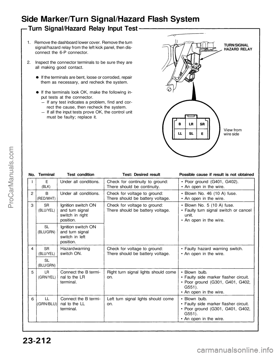
Side Marker/Turn Signal/Hazard Flash System
Turn Signal/Hazard Relay Input Test
1. Remove the dashboard lower cover. Remove the turn signal/hazard relay from the left kick panel, then dis-
connect the 6-P connector.
2. Inspect the connector terminals to be sure they are all making good contact.
If the terminals are bent, loose or corroded, repair
them as necessary, and recheck the system.
If the terminals look OK, make the following in-
put tests at the connector. If any test indicates a problem, find and cor-
rect the cause, then recheck the system. If all the input tests prove OK, the control unit
must be faulty; replace it.
View from
wire side
TURN/SIGNAL
HAZARD RELAY
1
2
3
4
5
6
B
(RED/WHT)
SR
(BLU/YEL)
SL
(BLU/GRN)
SR
(BLU/YEL)
SL
(BLU/GRN)
LR
(GRN/YEL)
LL
(GRN/BLU)
Test condition
Under all conditions.
Ignition switch ON
and turn signal
switch in right position.
Ignition switch ON
and turn signal switch in left
position.
Connect the B termi-
nal to the LR
terminal.
Connect the B termi-
nal to the LL
terminal.
Test: Desired result
Check for continuity to ground:
There should be continuity.
Check for voltage to ground:
There should be battery voltage.
Check for voltage to ground:
There should be battery voltage.
Check for voltage to ground:
There should be battery voltage.
Right turn signal lights should come
on.
Left turn signal lights should come
on.
Possible cause if result is not obtained
Poor ground (G401, G402).
An open in the wire.
Blown No. 46 (10 A) fuse.
An open in the wire.
Blown No. 5 (10 A) fuse.
Faulty turn signal switch or cancel
unit.
An open in the wire.
Faulty hazard warning switch.
An open in the wire.
Blown bulb.
Faulty side marker flasher circuit.
Poor ground (G301, G401, G402,
G551).
An open in the wire.
Blown bulb.
Faulty side marker flasher circuit.
Poor ground (G301, G401, G402,
G551).
An open in the wire.
E
(BLK)
Terminal
No.
Under all conditions.
Hazard warning
switch ON.ProCarManuals.com
Page 1419 of 1640

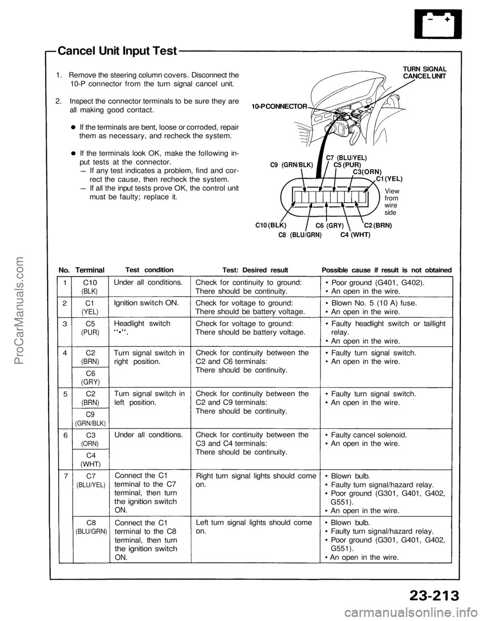
Cancel Unit Input Test
1. Remove the steering column covers. Disconnect the 10-P connector from the turn signal cancel unit.
2. Inspect the connector terminals to be sure they are all making good contact.
If the terminals are bent, loose or corroded, repair
them as necessary, and recheck the system.
If the terminals look OK, make the following in-
put tests at the connector. If any test indicates a problem, find and cor-
rect the cause, then recheck the system. If all the input tests prove OK, the control unit
must be faulty; replace it.
C9 (GRN/BLK)
C10
(BLK)
10-P CONNECTOR
TURN SIGNAL
CANCEL UNIT
C7 (BLU/YEL)
C5
(PUR)
C3(ORN)
C1
(YEL)
View
from
wire
side
C2
(BRN)
C4
(WHT)
C6
(GRY)
C8 (BLU/GRN)
Test condition
Under all conditions.
Ignition switch ON.
Headlight switch
Turn signal switch in right position.
Turn signal switch in
left position.
Under all conditions.
Connect the C1
terminal to the C7
terminal, then turn
the ignition switch
ON.
Connect the C1
terminal to the C8
terminal, then turn
the ignition switch
ON.
Test: Desired result
Check for continuity to ground:
There should be continuity.
Check for voltage to ground:
There should be battery voltage.
Check for voltage to ground:
There should be battery voltage.
Check for continuity between the
C2 and C6 terminals:
There should be continuity.
Check for continuity between the
C2 and C9 terminals:
There should be continuity.
Check for continuity between the
C3 and C4 terminals:
There should be continuity.
Right turn signal lights should come
on.
Left turn signal lights should come
on.
Possible cause if result is not obtained
Poor ground (G401, G402).
An open in the wire.
Blown No. 5 (10 A) fuse.
An open in the wire.
Faulty headlight switch or taillight
relay.
An open in the wire.
Faulty turn signal switch.
An open in the wire.
Faulty turn signal switch.
An open in the wire.
Faulty cancel solenoid.
An open in the wire.
Blown bulb.
Faulty turn signal/hazard relay.
Poor ground (G301, G401, G402,
G551).
An open in the wire.
Blown bulb.
Faulty turn signal/hazard relay.
Poor ground (G301, G401, G402,
G551).
An open in the wire.
No.
Terminal
C10
(BLK)
1
2
C1
(YEL)
C5
(PUR)
3
4
C2
(BRN)
C6
(GRY)
5
C2
(BRN)
C9
(GRN/BLK)
6
C3
(ORN)
C4
(WHT)
7
C7
(BLU/YEL)
C8
(BLU/GRN)ProCarManuals.com
Page 1423 of 1640
Power Door Locks
Component Location Index
UNDER-HOOD FUSE/BELAY BOX
Located at right side offront compartment
IGNITION KEY SWITCH
Test, page 23-167
DRIVER'S DOOR LOCK SWITCH
Test
,
page 23-260
DRIVER'S DOOR LOCK
ACTUATOR ASSEMBLY
Test
,
page 23-258Replacement
,
section 20
DRIVER'S DOOR SWITCH
Test, page 23-198
PASSENGERS'S DOOR LOCK
ACTUATOR ASSEMBLY
Test
,
page 23-259Replacement
,
section 20
PASSENGER'S DOOR SWITCH
Test
,
page 23-198
PASSENGER'S DOOR LOCK
SWITCH
Test
,
page 23-260
POWER DOOR LOCK
CONTROL UNIT
Inpu
t
Test,
ProCarManuals.com
Page 1426 of 1640

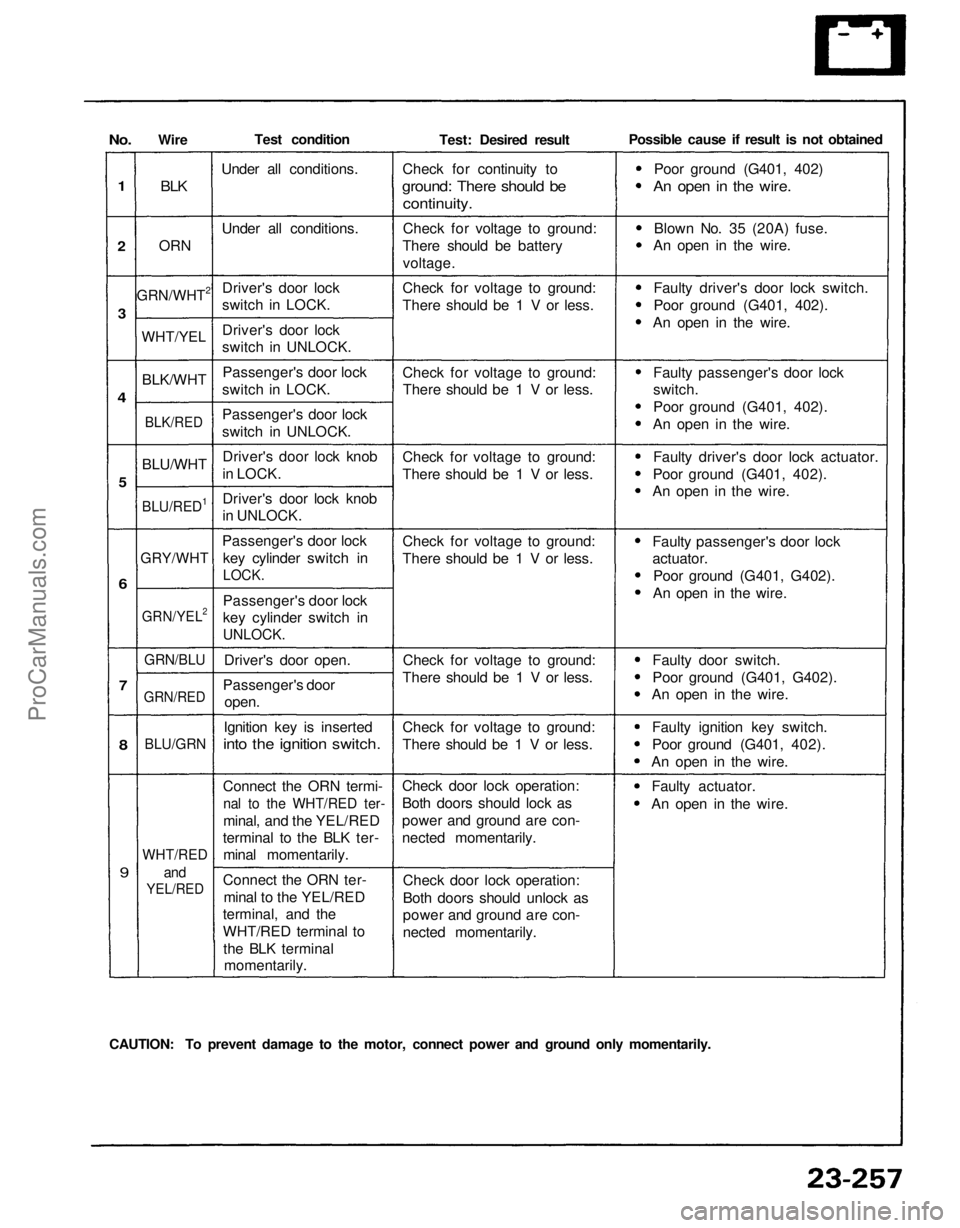
No.
1
2
3
4
5
6
7
8
9
Wire
BLK
ORN
GRN/WHT2
WHT/YEL
BLK/WHT
BLK/RED
BLU/WHT
BLU/RED1
GRY/WHT
GRN/YEL2
GRN/BLU
GRN/RED
BLU/GRN
WHT/RED
and
YEL/RED
Test condition
Under all conditions.
Under all conditions.Driver's door lock
switch in LOCK.
Driver's door lock
switch in UNLOCK.Passenger's door lock
switch in LOCK.
Passenger's door lock
switch in UNLOCK.
Driver's door lock knob
in LOCK.
Driver's door lock knob
in UNLOCK.
Passenger's door lock key cylinder switch in
LOCK.
Passenger's door lock
key cylinder switch in
UNLOCK.
Driver's door open.
Passenger's door open.
Ignition key is inserted
into the ignition switch.
Connect the ORN termi-
nal to the WHT/RED ter-
minal, and the YEL/RED
terminal to the BLK ter- minal momentarily.
Connect the ORN ter- minal to the YEL/RED
terminal, and the
WHT/RED terminal to
the BLK terminal momentarily. Test: Desired result
Check for continuity to
ground: There should be
continuity.
Check for voltage to ground:
There should be battery
voltage.
Check for voltage to ground:
There should be 1 V or less.
Check for voltage to ground: There should be 1 V or less.
Check for voltage to ground:
There should be 1 V or less.
Check for voltage to ground:
There should be 1 V or less.
Check for voltage to ground:
There should be 1 V or less.
Check for voltage to ground:
There should be 1 V or less.
Check door lock operation:
Both doors should lock as
power and ground are con-
nected momentarily.
Check door lock operation:
Both doors should unlock as
power and ground are con-
nected momentarily. Possible cause if result is not obtained
Poor ground (G401, 402)
An open in the wire.
Blown No. 35 (20A) fuse.
An open in the wire.
Faulty driver's door lock switch.
Poor ground (G401, 402).
An open in the wire.
Faulty passenger's door lock
switch.
Poor ground (G401, 402).
An open in the wire.
Faulty driver's door lock actuator.
Poor ground (G401, 402).
An open in the wire.
Faulty passenger's door lock
actuator.
Poor ground (G401, G402).
An open in the wire.
Faulty door switch.
Poor ground (G401, G402).
An open in the wire.
Faulty ignition key switch.
Poor ground (G401, 402).
An open in the wire.
Faulty actuator.
An open in the wire.
CAUTION: To prevent damage to the motor, connect power and ground only momentarily.ProCarManuals.com