1990 VOLKSWAGEN CORRADO width
[x] Cancel search: widthPage 504 of 906

EMISSION CONTROL VISUAL INSPECTION PROCEDURES
Article Text (p. 10)
1990 Volkswagen Corrado
For Volkswagen Technical Site: http://vw.belcom.ru
Copyright © 1998 Mitchell Repair Information Company, LLC
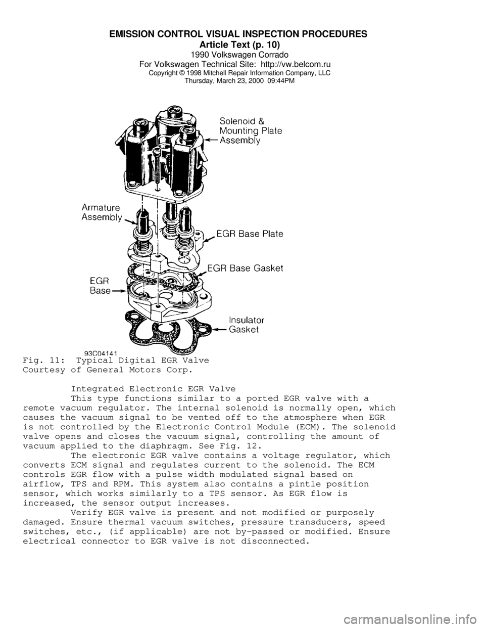
Thursday, March 23, 2000 09:44PMFig. 11: Typical Digital EGR Valve
Courtesy of General Motors Corp.
Integrated Electronic EGR Valve
This type functions similar to a ported EGR valve with a
remote vacuum regulator. The internal solenoid is normally open, which
causes the vacuum signal to be vented off to the atmosphere when EGR
is not controlled by the Electronic Control Module (ECM). The solenoid
valve opens and closes the vacuum signal, controlling the amount of
vacuum applied to the diaphragm. See Fig. 12.
The electronic EGR valve contains a voltage regulator, which
converts ECM signal and regulates current to the solenoid. The ECM
controls EGR flow with a pulse width modulated signal based on
airflow, TPS and RPM. This system also contains a pintle position
sensor, which works similarly to a TPS sensor. As EGR flow is
increased, the sensor output increases.
Verify EGR valve is present and not modified or purposely
damaged. Ensure thermal vacuum switches, pressure transducers, speed
switches, etc., (if applicable) are not by-passed or modified. Ensure
electrical connector to EGR valve is not disconnected.
Page 520 of 906

ENGINE OVERHAUL PROCEDURES - GENERAL INFORMATION
Article Text (p. 11)
1990 Volkswagen Corrado
For Volkswagen Technical Site: http://vw.belcom.ru
Copyright © 1998 Mitchell Repair Information Company, LLC
Thursday, March 23, 2000 09:44PM
grinding machine.
Valve Lapping
During valve lapping of recent designed valves, be sure to
follow manufacturers recommendations. Surface hardening and materials
used with some valves do not permit lapping. Lapping process will
remove excessive amounts of the hardened surface.
Valve lapping is done to ensure adequate sealing between
valve face and seat. Use either a hand drill or lapping stick with
suction cup attached.
Moisten and attach suction cup to valve. Lubricate valve stem
and guide. Apply a thin coat of fine valve grinding compound between
valve and seat. Rotate lapping tool between the palms or with hand
drill.
Lift valve upward off the seat and change position often.
This is done to prevent grooving of valve seat. Lap valve until a
smooth polished seat is obtained. Thoroughly clean grinding compound
from components. Valve to valve seat concentricity should be checked.
See VALVE SEAT CONCENTRICITY.
CAUTION: Valve guides must be in good condition and free of carbon
deposits prior to valve seat grinding. Some engines contain
an induction hardened valve seat. Excessive material removal
will damage valve seats.
Valve Seat Grinding
Select coarse stone of correct size and angle for seat to be
ground. Ensure stone is true and has a smooth surface. Select correct
size pilot for valve guide dimension. Install pilot in valve guide.
Lightly lubricate pilot shaft. Install stone on pilot. Move stone off
and on the seat approximately 2 times per second during grinding
operation.
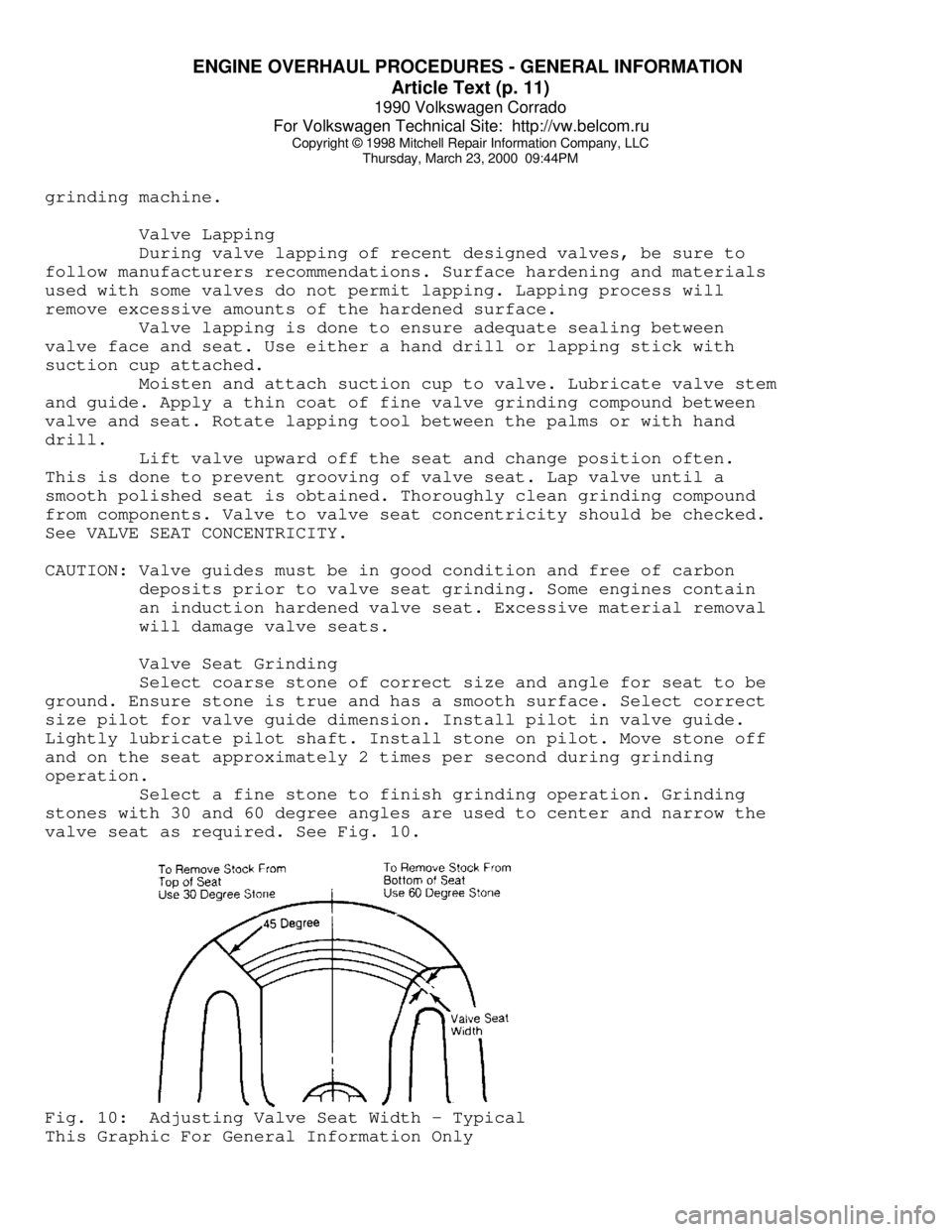
Select a fine stone to finish grinding operation. Grinding
stones with 30 and 60 degree angles are used to center and narrow the
valve seat as required. See Fig. 10.Fig. 10: Adjusting Valve Seat Width - Typical
This Graphic For General Information Only
Page 531 of 906

ENGINE OVERHAUL PROCEDURES - GENERAL INFORMATION
Article Text (p. 22)
1990 Volkswagen Corrado
For Volkswagen Technical Site: http://vw.belcom.ru
Copyright © 1998 Mitchell Repair Information Company, LLC
Thursday, March 23, 2000 09:44PM
rotated.
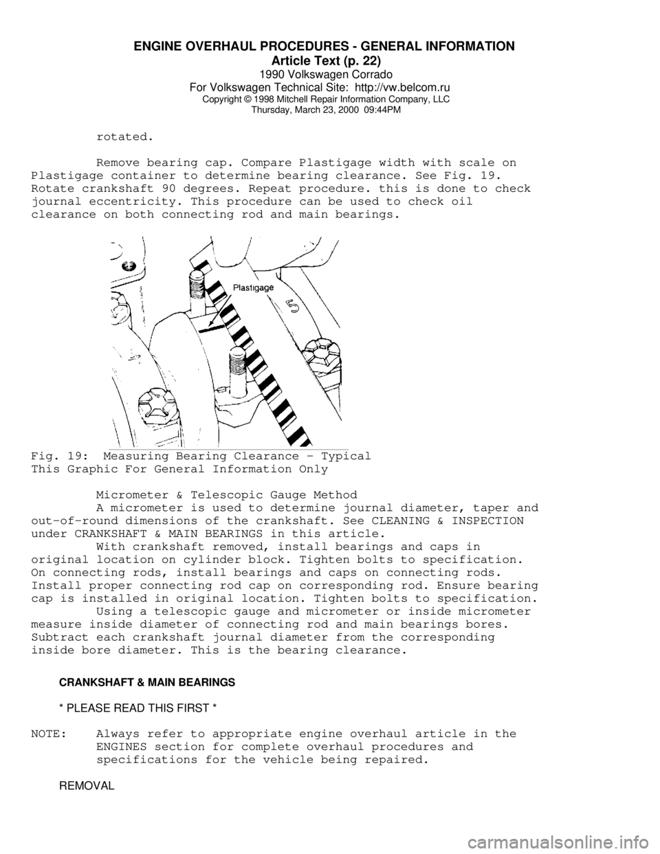
Remove bearing cap. Compare Plastigage width with scale on
Plastigage container to determine bearing clearance. See Fig. 19.
Rotate crankshaft 90 degrees. Repeat procedure. this is done to check
journal eccentricity. This procedure can be used to check oil
clearance on both connecting rod and main bearings.Fig. 19: Measuring Bearing Clearance - Typical
This Graphic For General Information Only
Micrometer & Telescopic Gauge Method
A micrometer is used to determine journal diameter, taper and
out-of-round dimensions of the crankshaft. See CLEANING & INSPECTION
under CRANKSHAFT & MAIN BEARINGS in this article.
With crankshaft removed, install bearings and caps in
original location on cylinder block. Tighten bolts to specification.
On connecting rods, install bearings and caps on connecting rods.
Install proper connecting rod cap on corresponding rod. Ensure bearing
cap is installed in original location. Tighten bolts to specification.
Using a telescopic gauge and micrometer or inside micrometer
measure inside diameter of connecting rod and main bearings bores.
Subtract each crankshaft journal diameter from the corresponding
inside bore diameter. This is the bearing clearance.
CRANKSHAFT & MAIN BEARINGS
* PLEASE READ THIS FIRST *
NOTE: Always refer to appropriate engine overhaul article in the
ENGINES section for complete overhaul procedures and
specifications for the vehicle being repaired.
REMOVAL
Page 535 of 906

ENGINE OVERHAUL PROCEDURES - GENERAL INFORMATION
Article Text (p. 26)
1990 Volkswagen Corrado
For Volkswagen Technical Site: http://vw.belcom.ru
Copyright © 1998 Mitchell Repair Information Company, LLC
Thursday, March 23, 2000 09:44PM
CYLINDER BORE INSPECTION
Inspect the bore for scuffing or roughness. Cylinder bore
is dimensionally checked for out-of-round and taper using dial bore
gauge. For determining out-of-round, measure cylinder parallel and
perpendicular to the block centerline. Difference in the 2 readings
is the bore out-of-round. Cylinder bore must be checked at top, middle
and bottom of piston travel area.
Bore taper is obtained by measuring bore at the top and
bottom. If wear has exceeded allowable limits, block must be honed
or bored to next available oversize piston dimension.
CYLINDER HONING
Cylinder must be properly honed to allow new piston rings to
properly seat. Cross-hatching at correct angle and depth is critical
to lubrication of cylinder walls and pistons.
A flexible drive hone and power drill are commonly used.
Drive hone must be lubricated during operation. Mix equal parts of
kerosene and SAE 20w engine oil for lubrication.
Apply lubrication to cylinder wall. Operate cylinder hone
from top to bottom of cylinder using even strokes to produce 45 degree
cross-hatch pattern on the cylinder wall. DO NOT allow cylinder hone
to extend below cylinder during operation.
Recheck bore dimension after final honing. Wash cylinder
wall with hot soapy water to remove abrasive particles. Blow dry with
compressed air. Coat cleaned cylinder walls with lubricating oil.
DECK WARPAGE
Check deck for damage or warped head sealing surface. Place
a straightedge across gasket surface of the deck. Using feeler gauge,
measure clearance at center of straightedge. Measure across width and
length of cylinder block at several points.
If warpage exceeds specifications, deck must be resurfaced.
If warpage exceeds manufacturer's maximum tolerance for material
removal, replace block.
DECK HEIGHT
Distance from the crankshaft centerline to the block
deck is termed the deck height. Measure and record front and rear main
journals of crankshaft. To compute this distance, install crankshaft
and retain with center main bearing and cap only. Measure distance
from the crankshaft journal to the block deck, parallel to the
cylinder centerline.
Add one half of the main bearing journal diameter to distance
from crankshaft journal to block deck. This dimension should be
checked at front and rear of cylinder block. Both readings should be
the same.
If difference exceeds specifications, cylinder block must be
repaired or replaced. Deck height and warpage should be corrected at
Page 603 of 906

INSTRUMENT PANEL
Article Text
1990 Volkswagen Corrado
For Volkswagen Technical Site: http://vw.belcom.ru
Copyright © 1998 Mitchell Repair Information Company, LLC
Thursday, March 23, 2000 09:46PM
ARTICLE BEGINNING
1989-90 ACCESSORIES & EQUIPMENT
Volkswagen Instrument Panels
Cabriolet, Fox, Golt, GTI, Jetta, Jetta GLI, Vanagon
DESCRIPTION & OPERATION
Instrument cluster for most models includes speedometer, fuel
gauge and temperature gauge. Optional instruments include clock,
tachometer, voltmeter and oil temperature gauge.
Printed circuit provides voltage to gauges. A voltage
regulator attached to the printed circuit controls voltage to fuel and
temperature gauges. Light Emitting Diodes (LEDs) are used for most
warning lights. To replace diodes, pull from printed circuit sockets.
NOTE: Volkswagen Tester (1301) is required for resistance tests.
Tester settings are numerical. Settings do not indicate
resistance in ohms. Manufacturer does not supply resistance
value in ohms.
TESTING
FUEL & TEMPERATURE GAUGE
1) Disconnect wire from fuel tank or temperature sending
unit. Connect VW tester between wire and ground. Turn ignition on and
allow 2 minutes for gauge reading to stabilize. Use FUEL GAUGE TESTING
or TEMPERATURE GAUGE TESTING table to compare gauge reading. Gauge
should be within one pointer width of specification.
2) If gauge needle does not move, check continuity between
sender wire and gauge. If needle moves, but does not match
specifications, replace gauge. If gauge works correctly with tester,
but not sending unit, replace sending unit.
FUEL GAUGE TESTINGÄÄÄÄÄÄÄÄÄÄÄÄÄÄÄÄÄÄÄÄÄÄÄÄÄÄÄÄÄÄÄÄÄÄÄÄÄÄÄÄÄÄÄÄÄÄÄÄÄÄÄÄÄÄÄApplication Dial Setting Indicator
Cabriolet & Fox .......... 55 ................ Full
560 ................Empty
Golf, GTI, Jetta
& Jetta GLI .............. 52 ................ Full
550 ................Empty
Vanagon .................. 50 ................ Full
320 ................Empty
ÄÄÄÄÄÄÄÄÄÄÄÄÄÄÄÄÄÄÄÄÄÄÄÄÄÄÄÄÄÄÄÄÄÄÄÄÄÄÄÄÄÄÄÄÄÄÄÄÄÄÄÄÄÄÄTEMPERATURE GAUGE TESTING
ÄÄÄÄÄÄÄÄÄÄÄÄÄÄÄÄÄÄÄÄÄÄÄÄÄÄÄÄÄÄÄÄÄÄÄÄÄÄÄÄÄÄÄÄÄÄÄÄÄÄÄÄÄÄÄ
Page 685 of 906

SCHEDULED SERVICES
Article Text (p. 2)
1990 Volkswagen Corrado
For Volkswagen Technical Site: http://vw.belcom.ru
Copyright © 1998 Mitchell Repair Information Company, LLC
Thursday, March 23, 2000 09:49PM
SUPPLEMENTAL RESTRAINT SYSTEM (SRS) AIR BAR WARNING
NOTE: For information on air bag DIAGNOSIS & TESTING or DISPOSAL
PROCEDURES, see AIR BAGS article in the ACCESSORIES/SAFETY
EQUIPMENT Section.
System circuit is grounded by 2 screws beneath the driver's
seat. DO NOT use these screws to ground any other accessory. DO NOT
ground any other components near this system.
AIR CONDITIONING SERVICING (1993 & LATER)
CAUTION: Avoid breathing R-134a refrigerant and PAG lubricant vapors,
exposure may irritate eyes, nose and throat. To remove
R-134a from system use R-134a recycling equipment that meets
SAE J2210 specifications. If accidental system discharge
occurs, ventilate work area before resuming service.
WARNING: R-134a service equipment or vehicle A/C systems SHOULD NOT
be pressure tested or leak tested with compressed air. Some
mixtures of air/R134a have shown to be combustible at
elevated pressures. These mixtures are dangerous and may
cause fire and/or explosions. See AIR CONDITIONING SERVICE
article in GENERAL INFORMATION section.
ANTI-LOCK BRAKE SYSTEM
The anti-lock brake system contains electronic equipment that
can be susceptible to interference caused by improperly installed or
high output radio transmitting equipment. Since this interference
could cause the possible loss of the anti-lock braking capability,
such equipment should be installed by qualified professionals.
On models equipped with anti-lock brake systems, ALWAYS
observe the following cautions:
* DO NOT attempt to bleed hydraulic system without first
referring to the appropriate ANTI-LOCK BRAKE SYSTEM article
in the BRAKES Section.
* DO NOT mix tire sizes. As long as tires remain close to the
original diameter, increasing the width is acceptable.
Rolling diameter must be identical for all 4 tires. Some
manufacturers recommend tires of the same brand, style and
type. Failure to follow this precaution may cause inaccurate
wheel speed readings.
* Use ONLY recommended brake fluids. DO NOT use silicone brake
fluids in an ABS-equipped vehicle.
BATTERY WARNING
WARNING: When battery is disconnected, vehicles equipped with
computers may lose memory data. When battery power is
Page 808 of 906

TROUBLE SHOOTING - BASIC PROCEDURES
Article Text (p. 32)
1990 Volkswagen Corrado
For Volkswagen Technical Site: http://vw.belcom.ru
Copyright © 1998 Mitchell Repair Information Company, LLC
Thursday, March 23, 2000 09:52PM
Loose rocker arms Retighten rocker arms,
See ENGINES
Excessive valve seat Reface valve seats, See
run-out ENGINES
Missing valve lock Install new valve lock
Excessively worn camshaft Replace camshaft, See
lobes ENGINES
Plugged valve lifter oil Eliminate restriction
holes or replace lifter
Faulty valve lifter check Replace lifter check
ball ball, See ENGINES
Rocker arm nut installed Remove and reinstall
upside down correctly
Valve lifter incorrect for Remove and replace
engine valve lifters
Faulty push rod seat or Replace plunger or push
lifter plunger rodÄÄÄÄÄÄÄÄÄÄÄÄÄÄÄÄÄÄÄÄÄÄÄÄÄÄÄÄÄÄÄÄÄÄÄÄÄÄÄÄÄÄÄÄÄÄÄÄÄÄÄÄÄÄÄÄÄÄÄÄÄÄÄÄÄÄÄÄÄÄNoisy Valves Improper valve lash Re-adjust valve lash,
See ENGINES
Worn or dirty valve lifters Clean and/or replace
lifters
Worn valve guides Replace valve guides,
See ENGINES
Excessive valve seat or Reface seats or valve
face run-out face
Worn camshaft lobes Replace camshaft, See
ENGINES
Loose rocker arm studs Re-tighten rocker arm
studs, See ENGINES
Bent push rods Replace push rods, See
ENGINES
Broken valve springs Replace valve springs,
See ENGINES
ÄÄÄÄÄÄÄÄÄÄÄÄÄÄÄÄÄÄÄÄÄÄÄÄÄÄÄÄÄÄÄÄÄÄÄÄÄÄÄÄÄÄÄÄÄÄÄÄÄÄÄÄÄÄÄÄÄÄÄÄÄÄÄÄÄÄÄÄÄÄBurned,Sticking Weak valve springs or Replace valves and/or
or Broken Valves warped valves springs, See ENGINES
Improper lifter clearance Re-adjust clearance or
replace lifters
Worn guides or improper Replace valve guides,
guide clearance See ENGINES
Out-of-round valve seats Re-grind valve seats
or improper seat width
Gum deposits on valve Remove deposits
stems, seats or guides
Improper spark timing Re-adjust spark timing
ÄÄÄÄÄÄÄÄÄÄÄÄÄÄÄÄÄÄÄÄÄÄÄÄÄÄÄÄÄÄÄÄÄÄÄÄÄÄÄÄÄÄÄÄÄÄÄÄÄÄÄÄÄÄÄÄÄÄÄÄÄÄÄÄÄÄÄÄÄÄBroken Undersize pistons Replace with larger
Pistons/Rings pistons, See ENGINES
Wrong piston rings Replace with correct
rings, See ENGINES
Out-of-round cylinder bore Re-bore cylinder bore
Page 846 of 906

WAVEFORMS - INJECTOR PATTERN TUTORIAL
Article Text (p. 2)
1990 Volkswagen Corrado
For Volkswagen Technical Site: http://vw.belcom.ru
Copyright © 1998 Mitchell Repair Information Company, LLC
Thursday, March 23, 2000 09:52PM
necessary to do a thorough job, or will a set of noid lights and a
multifunction DVOM do just as well?"
In the following text, we are going to look at what noid
lights and DVOMs do best, do not do very well, and when they can
mislead you. As you might suspect, the lab scope, with its ability to
look inside an active circuit, comes to the rescue by answering for
the deficiencies of these other tools.
OVERVIEW OF NOID LIGHT
The noid light is an excellent "quick and dirty" tool. It can
usually be hooked to a fuel injector harness fast and the flashing
light is easy to understand. It is a dependable way to identify a no-
pulse situation.
However, a noid light can be very deceptive in two cases:
* If the wrong one is used for the circuit being tested.
Beware: Just because a connector on a noid light fits the
harness does not mean it is the right one.
* If an injector driver is weak or a minor voltage drop is
present.
Use the Right Noid Light
In the following text we will look at what can happen if the
wrong noid light is used, why there are different types of noid lights
(besides differences with connectors), how to identify the types of
noid lights, and how to know the right type to use.
First, let's discuss what can happen if the incorrect type of
noid light is used. You might see:
* A dimly flashing light when it should be normal.
* A normal flashing light when it should be dim.
A noid light will flash dim if used on a lower voltage
circuit than it was designed for. A normally operating circuit would
appear underpowered, which could be misinterpreted as the cause of a
fuel starvation problem.
Here are the two circuit types that could cause this problem:
* Circuits with external injector resistors. Used predominately
on some Asian & European systems, they are used to reduce the
available voltage to an injector in order to limit the
current flow. This lower voltage can cause a dim flash on a
noid light designed for full voltage.
* Circuits with current controlled injector drivers (e.g. "Peak
and Hold"). Basically, this type of driver allows a quick
burst of voltage/current to flow and then throttles it back
significantly for the remainder of the pulse width duration.
If a noid light was designed for the other type of driver
(voltage controlled, e.g. "Saturated"), it will appear dim
because it is expecting full voltage/current to flow for the
entire duration of the pulse width.