1990 VOLKSWAGEN CORRADO battery location
[x] Cancel search: battery locationPage 294 of 906

1.8L 4-CYL 8-VALVE & 1.8L 4-CYL 16-VALVE
Article Text (p. 3)
1990 Volkswagen Corrado
For Volkswagen Technical Site: http://vw.belcom.ru
Copyright © 1998 Mitchell Repair Information Company, LLC
Thursday, March 23, 2000 09:40PM
shift as necessary. Evenly tighten mount bolts in reverse order of
loosening. Fill fluids to proper level. Adjust clutch pedal (if
equipped). Tighten all bolts and nuts to specifications.
ENGINE R & I (FOX)
REMOVAL (FOX)
1) Disconnect negative battery cable. Open heater valve,
coolant expansion tank and drain radiator through lower radiator hose.
Mark and disconnect all heater hoses. Disconnect electric cooling fan
and thermo switch. Remove lower and side radiator mounting bolts.
Remove fan, shroud and radiator. Remove M/T clutch cable (if
equipped).
2) Mark and disconnect electrical wiring and vacuum hoses (as
necessary). Disconnect throttle, cruise and kickdown linkage (if
equipped). Remove fuel injectors and install protective caps and
plugs. Leave fuel lines attached and remove cold start valve. Remove
charcoal canister and set aside.
3) Remove 3 upper engine-to-transaxle bolts. Remove intake
air duct. Remove left and right engine mount nuts. Disconnect and
remove starter assembly. Remove 2 lower engine-to-transaxle bolts.
Remove transaxle inspection cover plate. Disconnect exhaust inlet pipe
support and separate inlet pipe from exhaust manifold.
4) Support transaxle. Attach engine sling to engine lifting
hooks. Raise engine/transaxle until engine clears engine mounts.
Ensure transaxle is supported. Remove remaining engine-to-transaxle
bolts. Lift and separate engine from vehicle without transaxle.
INSTALLATION
Lubricate transaxle main shaft splines and contact area
between clutch release bearing and clutch pressure plate with MoS2
grease. DO NOT lubricate guide sleeve for clutch release bearing. To
complete installation, reverse removal procedure. DO NOT reuse self-
locking nuts. Ensure engine mounts are installed to original location.
Tighten engine mounts and subframe bolts with engine running at idle.
Page 373 of 906

AA - USING THIS SECTION (GENERAL HELP INFORMATION)
Article Text (p. 2)
1990 Volkswagen Corrado
For Volkswagen Technical Site: http://vw.belcom.ru
Copyright © 1998 Mitchell Repair Information Company, LLC
Thursday, March 23, 2000 09:41PM
If you want "TUNE-UP" type information, see D - ADJUSTMENTS
for the adjustment procedures. If you are familiar with the
procedures, but need a quick way to find the specification, go to C -
TUNE-UP SPECS or C - SPECIFICATIONS for the specifications pertaining
to the vehicle.
When diagnosing driveability problems, first go to F - BASIC
TESTING. This article is here to help eliminate wasted diagnostic
time. If the basic systems are working properly, go to G - TESTS W/
CODES.
If the vehicle still is having a driveability problem or if
the vehicle has no self-diagnostic system, go to H - TESTS W/O CODES.
This article will help you diagnose the problem by symptom, locate the
symptom exhibited by the vehicle, and inspect or test the items which
may be causing the problem.
After finding which specific system or component requires
testing, use the I - SYS/COMP TESTS article to tests the systems and
components. We have also included (when available) pin voltage charts
and sensor range charts. These can be found in J - PIN VOLTAGE CHARTS
and K - SENSOR RANGE CHARTS.
Also included in this section are wiring diagrams and vacuum
diagrams. These can be found in L - WIRING DIAGRAMS and M - VACUUM
DIAGRAMS.
When all diagnostic tests have been performed and the problem
has been discovered, it may be necessary to replace or overhaul the
defective part. This information can be found in
N - REMOVE/INSTALL/OHAUL.
The content of each of these articles is outlined below. As a
summary of the driveability diagnosis, see ROUTINE OUTLINE in this
article.
A - ENGINE/VIN ID
This article shows how to identify the model and engine by
its Vehicle Identification Number (VIN). A model coverage chart shows
each model and engine, the fuel system, ignition system and engine
code. The engine serial number locations are also included in this
article.
B - EMISSION APPLICATION
These charts identify the emission systems and sub-systems
applicable to each model and engine combination.
C - TUNE-UP SPECS
This is a collection of quick-reference type specifications.
This article is helpful when you are familiar with proper adjustment
procedures and only need specifications. Included in this section are:
* Battery specifications.
* Fluid capacities.
Page 563 of 906

FUSES & CIRCUIT BREAKERS
Article Text
1990 Volkswagen Corrado
For Volkswagen Technical Site: http://vw.belcom.ru
Copyright © 1998 Mitchell Repair Information Company, LLC
Thursday, March 23, 2000 09:45PM
ARTICLE BEGINNING
1990-94 ELECTRICAL
Volkswagen Fuses & Circuit Breakers
Corrado
FUSES & CIRCUIT BREAKERS
FUSE PANEL LOCATION
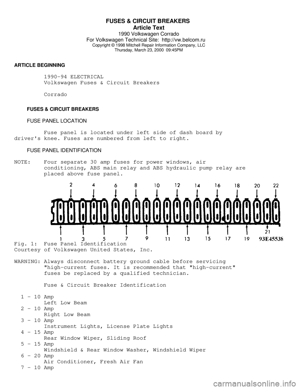
Fuse panel is located under left side of dash board by
driver's knee. Fuses are numbered from left to right.
FUSE PANEL IDENTIFICATION
NOTE: Four separate 30 amp fuses for power windows, air
conditioning, ABS main relay and ABS hydraulic pump relay are
placed above fuse panel.Fig. 1: Fuse Panel Identification
Courtesy of Volkswagen United States, Inc.
WARNING: Always disconnect battery ground cable before servicing
"high-current fuses. It is recommended that "high-current"
fuses be replaced by a qualified technician.
Fuse & Circuit Breaker Identification
1 - 10 Amp
Left Low Beam
2 - 10 Amp
Right Low Beam
3 - 10 Amp
Instrument Lights, License Plate Lights
4 - 15 Amp
Rear Window Wiper, Sliding Roof
5 - 15 Amp
Windshield & Rear Window Washer, Windshield Wiper
6 - 20 Amp
Air Conditioner, Fresh Air Fan
7 - 10 Amp
Page 594 of 906

I - SYSTEM/COMPONENT TESTS
Article Text (p. 7)
1990 Volkswagen Corrado
For Volkswagen Technical Site: http://vw.belcom.ru
Copyright © 1998 Mitchell Repair Information Company, LLC
Thursday, March 23, 2000 09:46PM
1) Disconnect throttle valve switch connector. With ohmmeter
set on 200-ohm scale, attach probes to male terminals. Ensure throttle
valve switch is completely closed. With throttle valve closed, meter
reading should be zero.
2) Position throttle valve to 1/2 open position. Ohmmeter
reading should be infinite. Position throttle to fully open position.
Ohmmeter reading should be zero. If any reading is incorrect, perform
throttle valve switch adjustment. See D - ADJUSTMENTS article.
3) If correct specifications cannot be obtained, check
throttle shaft play, accelerator cable adjustment and throttle switch
actuating cam. If okay, replace throttle valve switch.
RELAYS
FUEL PUMP RELAY (CABRIOLET, GOLF GL/GTI & JETTA)
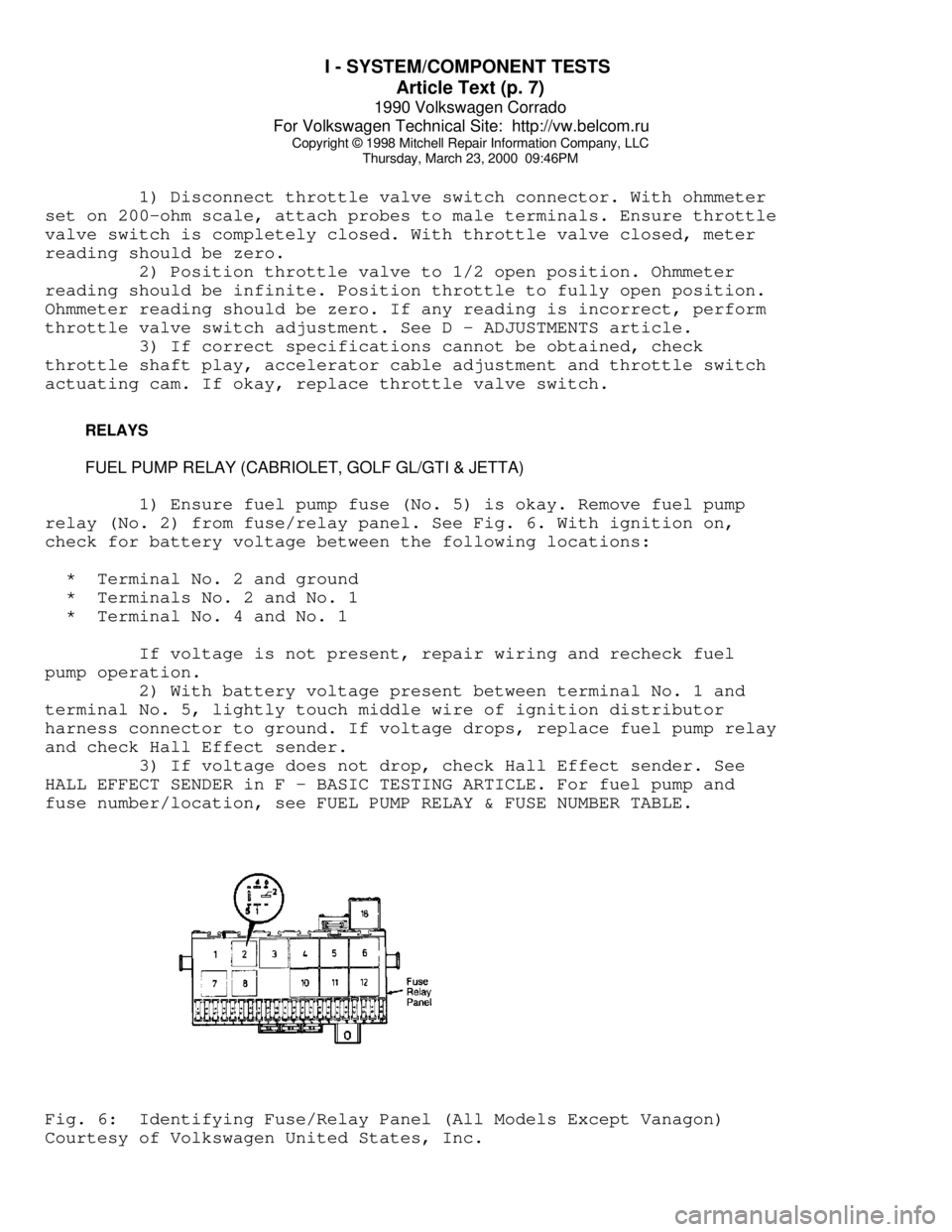
1) Ensure fuel pump fuse (No. 5) is okay. Remove fuel pump
relay (No. 2) from fuse/relay panel. See Fig. 6. With ignition on,
check for battery voltage between the following locations:
* Terminal No. 2 and ground
* Terminals No. 2 and No. 1
* Terminal No. 4 and No. 1
If voltage is not present, repair wiring and recheck fuel
pump operation.
2) With battery voltage present between terminal No. 1 and
terminal No. 5, lightly touch middle wire of ignition distributor
harness connector to ground. If voltage drops, replace fuel pump relay
and check Hall Effect sender.
3) If voltage does not drop, check Hall Effect sender. See
HALL EFFECT SENDER in F - BASIC TESTING ARTICLE. For fuel pump and
fuse number/location, see FUEL PUMP RELAY & FUSE NUMBER TABLE.Fig. 6: Identifying Fuse/Relay Panel (All Models Except Vanagon)
Courtesy of Volkswagen United States, Inc.
Page 595 of 906

I - SYSTEM/COMPONENT TESTS
Article Text (p. 8)
1990 Volkswagen Corrado
For Volkswagen Technical Site: http://vw.belcom.ru
Copyright © 1998 Mitchell Repair Information Company, LLC
Thursday, March 23, 2000 09:46PM
FUEL PUMP RELAY (FOX)
1) Ensure fuel pump fuse (No. 13) is okay. Remove fuel pump
relay. Note terminals numbers molded on fuse/relay panel. With
ignition on, check for battery voltage between the following
locations:
* Terminal No. 46 and ground
* Terminal No. 48 and ground
2) If voltage is not present, current is not reaching the
relay. Repair wiring. Check fuel pump operation. If voltage is
present, check for battery voltage between the following locations:
* Terminals No. 48 and No. 50
* Terminals No. 46 and No. 50
If voltage is not present, terminal No. 50 (ground circuit)
is open. Repair wiring. Check fuel pump operation.
3) If voltage is present, check for battery voltage between
terminals No. 50 and No. 51. If voltage is not present, the ignition
signal is not reaching fuel pump relay. Repair wiring. Check fuel pump
operation.
4) If no faults can be found and fuel pump operates when
relay is by-passed, replace fuel pump relay. For fuel pump and fuse
number/location, see FUEL PUMP RELAY & FUSE NUMBER table.
FUEL PUMP RELAY (CORRADO)
1) Ensure fuel pump fuse No. 18 is okay. Remove fuel pump
relay No. 12 from fuse/relay panel. See Fig. 6. With ignition on,
check for battery voltage between the following locations:
* Terminal No. 6 and ground.
* Terminal No. 2 and ground.
* Terminals No. 6 and No. 4.
2) If battery voltage is not present, check wiring and repair
as needed. Check fuel pump operation. With ignition off, connect
voltmeter between terminals No. 2 and No. 3. Turn ignition on. Voltage
should be present for one second. If voltage is not present for one
second, check wiring to ECU or replace ECU. Check fuel pump relay
operation. For fuel pump and fuse number/location, see FUEL PUMP RELAY
& FUSE NUMBER table.
FUEL PUMP RELAY (VANAGON)
1) Check terminal No. 30 and terminal No. 86 of fuel pump
relay for battery voltage. If battery voltage is not present, check
circuit for short or open circuit.
2) If battery voltage is present, remove relay and attach
ohmmeter probe to relay box terminal No. 85. Attach other probe to
Page 636 of 906

MAINTENANCE INFORMATION
Article Text
1990 Volkswagen Corrado
For Volkswagen Technical Site: http://vw.belcom.ru
Copyright © 1998 Mitchell Repair Information Company, LLC
Thursday, March 23, 2000 09:48PM
ARTICLE BEGINNING
1990-94 MAINTENANCE
Volkswagen Maintenance Information
Corrado G60 (1990-92)
SLC (1992-94 USA)
VR6 (1992-94 Canada)
* PLEASE READ THIS FIRST *
NOTE: For scheduled maintenance intervals and the related fluid
capacities, fluid specifications and labor times for major
service intervals, see SCHEDULED SERVICES article in this
section. Warranty information and specifications for fluid
capacities, lubrication specifications, wheel and tire size,
and battery type are covered in this article.
MODEL IDENTIFICATION
VIN LOCATION
The Vehicle Identification Number (VIN) is located on the
left side of the dash panel at the base of the windshield. The VIN
chart explains the code characters.
VIN CODE ID EXPLANATION
Numbers preceding the explanations in the legend below refer
to the sequence of characters as listed on VIN identification label.
See VIN example below.ÚÄÄÄÄÄÄÄÄÄÄÄÄÄÄÄÄÄÄÄÄÄÄÄÄÄÄÄÄÄÄÄÄÄÄÄÄÄÄÄÄÄÄÄÄÄÄÄÄÄÄÄÄÄÄÄÄÄÄÄÄÄ¿
³ (VIN) W V W A B 0 5 3 2 M H 0 9 9 7 1 7
³
³ 1 2 3 4 5 6 7 8 9 10 11 12 13 14 15 16 17
³
ÀÄÄÄÄÄÄÄÄÄÄÄÄÄÄÄÄÄÄÄÄÄÄÄÄÄÄÄÄÄÄÄÄÄÄÄÄÄÄÄÄÄÄÄÄÄÄÄÄÄÄÄÄÄÄÄÄÄÄÄÄÄÙ1 - Manufacturing Country
W * Germany
1 * United States
3 * Mexico
9 * Brazil
2-3 - Manufacturer
VW * Volkswagen
4 - Series
D * 2-Door G60 (1990-92)
E * 2-Door SLC (1992-94 USA)
E * 2-Door VR6 (1992-94 Canada)
Page 648 of 906

MAINTENANCE INFORMATION
Article Text (p. 13)
1990 Volkswagen Corrado
For Volkswagen Technical Site: http://vw.belcom.ru
Copyright © 1998 Mitchell Repair Information Company, LLC
Thursday, March 23, 2000 09:48PM
FUSES & CIRCUIT BREAKERS
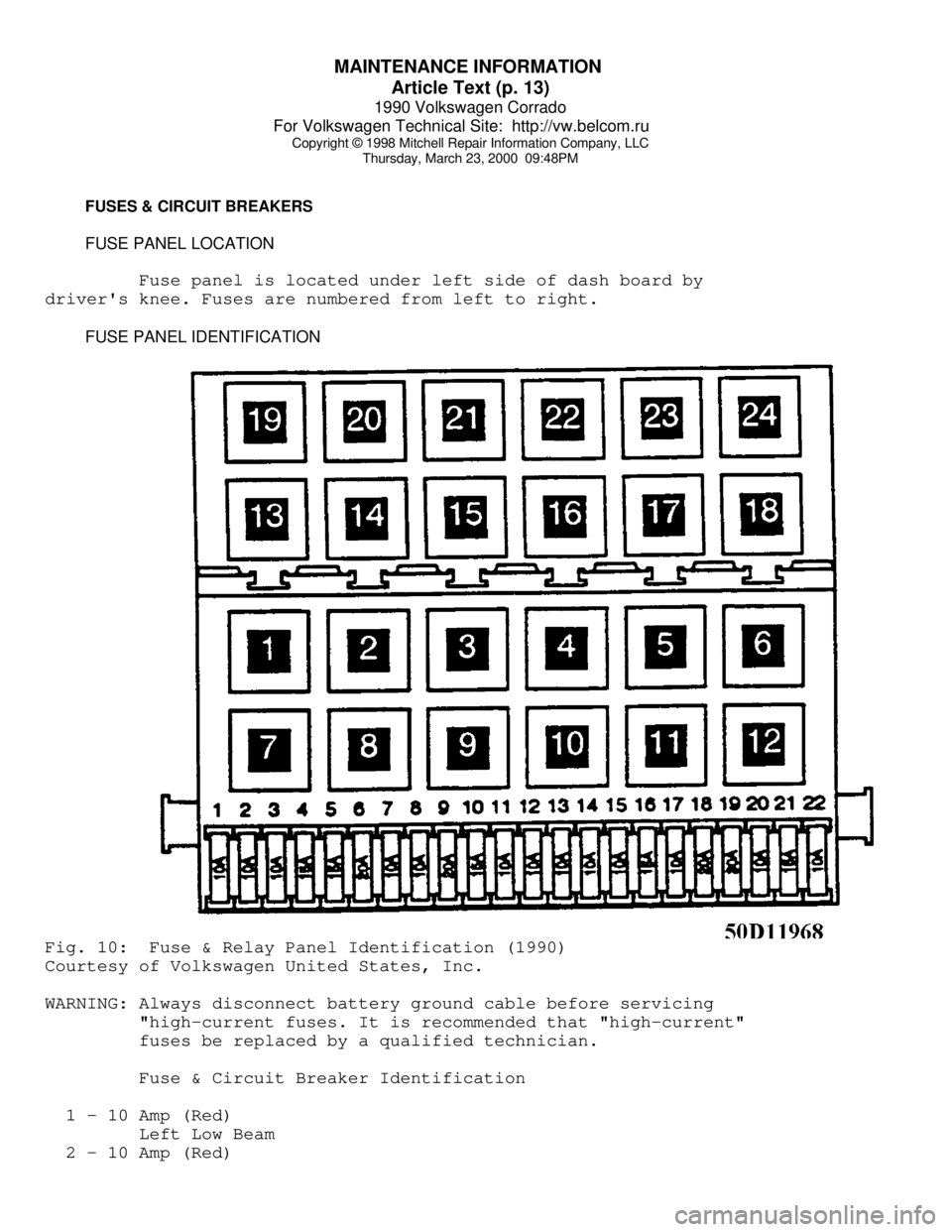
FUSE PANEL LOCATION
Fuse panel is located under left side of dash board by
driver's knee. Fuses are numbered from left to right.
FUSE PANEL IDENTIFICATIONFig. 10: Fuse & Relay Panel Identification (1990)
Courtesy of Volkswagen United States, Inc.
WARNING: Always disconnect battery ground cable before servicing
"high-current fuses. It is recommended that "high-current"
fuses be replaced by a qualified technician.
Fuse & Circuit Breaker Identification
1 - 10 Amp (Red)
Left Low Beam
2 - 10 Amp (Red)
Page 892 of 906

WIRING DIAGRAM SYMBOLS
Article Text (p. 2)
1990 Volkswagen Corrado
For Volkswagen Technical Site: http://vw.belcom.ru
Copyright © 1998 Mitchell Repair Information Company, LLC
Thursday, March 23, 2000 09:53PM
been created to make locating components easier. For these
articles, there will be a COMPONENT LOCATION MENU title in
the article main menu. These articles will also have the
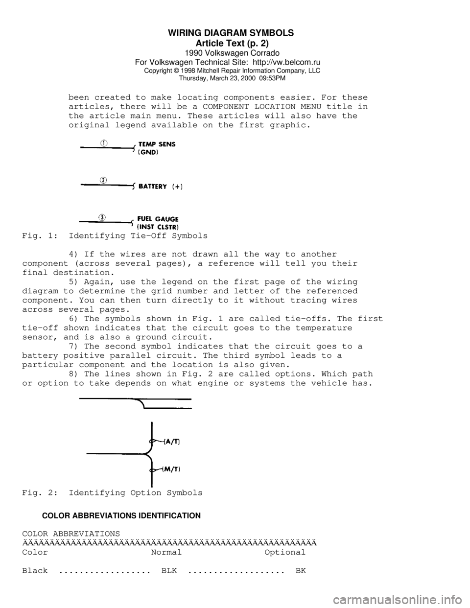
original legend available on the first graphic.Fig. 1: Identifying Tie-Off Symbols
4) If the wires are not drawn all the way to another
component (across several pages), a reference will tell you their
final destination.
5) Again, use the legend on the first page of the wiring
diagram to determine the grid number and letter of the referenced
component. You can then turn directly to it without tracing wires
across several pages.
6) The symbols shown in Fig. 1 are called tie-offs. The first
tie-off shown indicates that the circuit goes to the temperature
sensor, and is also a ground circuit.
7) The second symbol indicates that the circuit goes to a
battery positive parallel circuit. The third symbol leads to a
particular component and the location is also given.
8) The lines shown in Fig. 2 are called options. Which path
or option to take depends on what engine or systems the vehicle has.Fig. 2: Identifying Option Symbols
COLOR ABBREVIATIONS IDENTIFICATION
COLOR ABBREVIATIONSÄÄÄÄÄÄÄÄÄÄÄÄÄÄÄÄÄÄÄÄÄÄÄÄÄÄÄÄÄÄÄÄÄÄÄÄÄÄÄÄÄÄÄÄÄÄÄÄÄÄÄÄÄÄÄColor Normal Optional
Black .................. BLK ................... BK