1990 VOLKSWAGEN CORRADO fuel
[x] Cancel search: fuelPage 846 of 906

WAVEFORMS - INJECTOR PATTERN TUTORIAL
Article Text (p. 2)
1990 Volkswagen Corrado
For Volkswagen Technical Site: http://vw.belcom.ru
Copyright © 1998 Mitchell Repair Information Company, LLC
Thursday, March 23, 2000 09:52PM
necessary to do a thorough job, or will a set of noid lights and a
multifunction DVOM do just as well?"
In the following text, we are going to look at what noid
lights and DVOMs do best, do not do very well, and when they can
mislead you. As you might suspect, the lab scope, with its ability to
look inside an active circuit, comes to the rescue by answering for
the deficiencies of these other tools.
OVERVIEW OF NOID LIGHT
The noid light is an excellent "quick and dirty" tool. It can
usually be hooked to a fuel injector harness fast and the flashing
light is easy to understand. It is a dependable way to identify a no-
pulse situation.
However, a noid light can be very deceptive in two cases:
* If the wrong one is used for the circuit being tested.
Beware: Just because a connector on a noid light fits the
harness does not mean it is the right one.
* If an injector driver is weak or a minor voltage drop is
present.
Use the Right Noid Light
In the following text we will look at what can happen if the
wrong noid light is used, why there are different types of noid lights
(besides differences with connectors), how to identify the types of
noid lights, and how to know the right type to use.
First, let's discuss what can happen if the incorrect type of
noid light is used. You might see:
* A dimly flashing light when it should be normal.
* A normal flashing light when it should be dim.
A noid light will flash dim if used on a lower voltage
circuit than it was designed for. A normally operating circuit would
appear underpowered, which could be misinterpreted as the cause of a
fuel starvation problem.
Here are the two circuit types that could cause this problem:
* Circuits with external injector resistors. Used predominately
on some Asian & European systems, they are used to reduce the
available voltage to an injector in order to limit the
current flow. This lower voltage can cause a dim flash on a
noid light designed for full voltage.
* Circuits with current controlled injector drivers (e.g. "Peak
and Hold"). Basically, this type of driver allows a quick
burst of voltage/current to flow and then throttles it back
significantly for the remainder of the pulse width duration.
If a noid light was designed for the other type of driver
(voltage controlled, e.g. "Saturated"), it will appear dim
because it is expecting full voltage/current to flow for the
entire duration of the pulse width.
Page 848 of 906

WAVEFORMS - INJECTOR PATTERN TUTORIAL
Article Text (p. 4)
1990 Volkswagen Corrado
For Volkswagen Technical Site: http://vw.belcom.ru
Copyright © 1998 Mitchell Repair Information Company, LLC
Thursday, March 23, 2000 09:52PM
In any cases of doubt regarding the use of a noid light, a
lab scope will overcome all inherent weaknesses.
OVERVIEW OF DVOM
A DVOM is typically used to check injector resistance and
available voltage at the injector. Some techs also use it check
injector on-time either with a built-in feature or by using the
dwell/duty function.
There are situations where the DVOM performs these checks
dependably, and other situations where it can deceive you. It is
important to be aware of these strengths and weaknesses. We will cover
the topics above in the following text.
Checking Injector Resistance
If a short in an injector coil winding is constant, an
ohmmeter will accurately identify the lower resistance. The same is
true with an open winding. Unfortunately, an intermittent short is an
exception. A faulty injector with an intermittent short will show
"good" if the ohmmeter cannot force the short to occur during testing.
Alcohol in fuel typically causes an intermittent short,
happening only when the injector coil is hot and loaded by a current
high enough to jump the air gap between two bare windings or to break
down any oxides that may have formed between them.
When you measure resistance with an ohmmeter, you are only
applying a small current of a few milliamps. This is nowhere near
enough to load the coil sufficiently to detect most problems. As a
result, most resistance checks identify intermittently shorted
injectors as being normal.
There are two methods to get around this limitation. The
first is to purchase an tool that checks injector coil windings under
full load. The Kent-Moore J-39021 is such a tool, though there are
others. The Kent-Moore costs around $240 at the time of this writing
and works on many different manufacturer's systems.
The second method is to use a lab scope. Remember, a lab
scope allows you to see the regular operation of a circuit in real
time. If an injector is having an short or intermittent short, the lab
scope will show it.
Checking Available Voltage At the Injector
Verifying a fuel injector has the proper voltage to operate
correctly is good diagnostic technique. Finding an open circuit on the
feed circuit like a broken wire or connector is an accurate check with
a DVOM. Unfortunately, finding an intermittent or excessive resistance
problem with a DVOM is unreliable.
Let's explore this drawback. Remember that a voltage drop due
to excessive resistance will only occur when a circuit is operating?
Since the injector circuit is only operating for a few milliseconds at
a time, a DVOM will only see a potential fault for a few milliseconds.
The remaining 90+% of the time the unloaded injector circuit will show
normal battery voltage.
Since DVOMs update their display roughly two to five times a
Page 852 of 906

WAVEFORMS - INJECTOR PATTERN TUTORIAL
Article Text (p. 8)
1990 Volkswagen Corrado
For Volkswagen Technical Site: http://vw.belcom.ru
Copyright © 1998 Mitchell Repair Information Company, LLC
Thursday, March 23, 2000 09:52PM
Here is one example. Imagine a vehicle that has a faulty
injector driver that occasionally skips an injector pulse. Every
skipped pulse means that that cylinder does not fire, thus unburned O2
gets pushed into the exhaust and passes the O2 sensor. The O2 sensor
indicates lean, so the computer fattens up the mixture to compensate
for the supposed "lean" condition.
A connected dwell/duty meter would see the fattened pulse
width but would also see the skipped pulses. It would tally both and
likely come back with a reading that indicated the "pulse width" was
within specification because the rich mixture and missing pulses
offset each other.
This situation is not a far-fetched scenario. Some early GM
3800 engines were suffering from exactly this. The point is that a
lack of detail could cause misdiagnosis.
As you might have guessed, a lab scope would not miss this.
RELATIONSHIP BETWEEN DWELL & DUTY CYCLE READINGS TABLE (1)ÄÄÄÄÄÄÄÄÄÄÄÄÄÄÄÄÄÄÄÄÄÄÄÄÄÄÄÄÄÄÄÄÄÄÄÄÄÄÄÄÄÄÄÄÄÄÄÄÄÄÄÄÄÄÄÄÄÄÄÄDwell Meter (2) Duty Cycle Meter
1
ø .................................................... 1%
15
ø .................................................. 25%
30
ø .................................................. 50%
45
ø .................................................. 75%
60
ø ................................................. 100%
(1) - These are just some examples for your understanding.
It is okay to fill in the gaps.
(2) - Dwell meter on the six-cylinder scale.
ÄÄÄÄÄÄÄÄÄÄÄÄÄÄÄÄÄÄÄÄÄÄÄÄÄÄÄÄÄÄÄÄÄÄÄÄÄÄÄÄÄÄÄÄÄÄÄÄÄÄÄÄÄÄÄÄÄÄÄÄ THE TWO TYPES OF INJECTOR DRIVERS
OVERVIEW
There are two types of transistor driver circuits used to
operate electric fuel injectors: voltage controlled and current
controlled. The voltage controlled type is sometimes called a
"saturated switch" driver, while the current controlled type is
sometimes known as a "peak and hold" driver.
The basic difference between the two is the total resistance
of the injector circuit. Roughly speaking, if a particular leg in an
injector circuit has total resistance of 12 or more ohms, a voltage
control driver is used. If less than 12 ohms, a current control driver
is used.
It is a question of what is going to do the job of limiting
the current flow in the injector circuit; the inherent "high"
resistance in the injector circuit, or the transistor driver. Without
some form of control, the current flow through the injector would
cause the solenoid coil to overheat and result in a damaged injector.
VOLTAGE CONTROLLED CIRCUIT ("SATURATED SWITCH")
Page 883 of 906
WHEEL ALIGNMENT THEORY/OPERATION
Article Text
1990 Volkswagen Corrado
For Volkswagen Technical Site: http://vw.belcom.ru
Copyright © 1998 Mitchell Repair Information Company, LLC
Thursday, March 23, 2000 09:53PM
ARTICLE BEGINNING
GENERAL INFORMATION
Wheel Alignment Theory & Operation
ALL MODELS
* PLEASE READ THIS FIRST *
NOTE: This article is intended for general information purposes
only. This information may not apply to all makes and models.
PRE-ALIGNMENT INSTRUCTIONS
GENERAL ALIGNMENT CHECKS
Before adjusting wheel alignment, check the following:
* Each axle uses tires of same construction and tread style,
equal in tread wear and overall diameter. Verify that radial
and axial runout is not excessive. Inflation should be at
manufacturer's specifications.
* Steering linkage and suspension must not have excessive play.
Check for wear in tie rod ends and ball joints. Springs must
not be sagging. Control arm and strut rod bushings must not
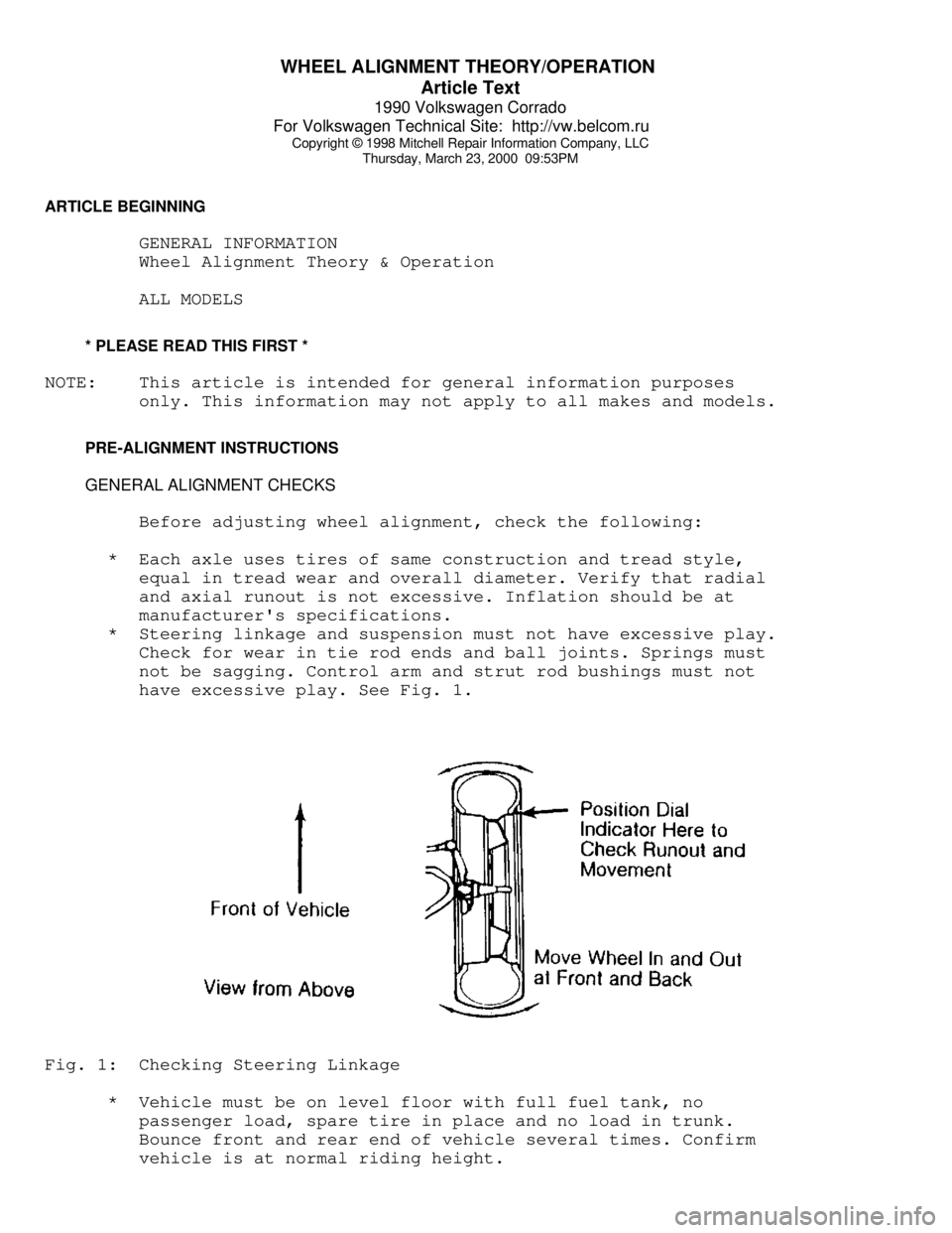
have excessive play. See Fig. 1.Fig. 1: Checking Steering Linkage
* Vehicle must be on level floor with full fuel tank, no
passenger load, spare tire in place and no load in trunk.
Bounce front and rear end of vehicle several times. Confirm
vehicle is at normal riding height.
Page 896 of 906

WIRING DIAGRAMS
Article Text
1990 Volkswagen Corrado
For Volkswagen Technical Site: http://vw.belcom.ru
Copyright © 1998 Mitchell Repair Information Company, LLC
Thursday, March 23, 2000 09:53PM
ARTICLE BEGINNING
1990 WIRING DIAGRAMS
Volkswagen
Corrado
COMPONENT LOCATION MENU
COMPONENT LOCATIONS TABLEÄÄÄÄÄÄÄÄÄÄÄÄÄÄÄÄÄÄÄÄÄÄÄÄÄÄÄÄÄÄÄÄÄÄÄÄÄÄÄÄÄÄÄÄÄÄÄÄÄÄÄÄÄÄÄÄÄÄÄÄComponent Figure No. (Location)
A/C COMP CLUTCH ................................. 4 (D 14)
A/C SYSTEM ................................. 4 (D-E 12-15)
ABS SYSTEM ................................... 2 (B-E 4-7)
ALTERNATOR ....................................... 1 (B 3)
AUTO SEAT BELTS ............................ 7 (B-E 25-27)
BACK-UP LIGHT SWITCH ............................ 6 (E 20)
BATTERY .......................................... 1 (A 2)
BEAM SELECT SWITCH .............................. 4 (A 12)
BRAKE & PARK BRAKE INDICATOR .................... 6 (A 22)
BRAKE FLUID LEVEL WARNING SWITCH ........ 2, 6 (E 6, A 23)
CASSETTE STORAGE LIGHT .......................... 6 (E 23)
CENTRAL LOCKS ................................ 8 (A 28-31)
CIG LIGHTER ..................................... 5 (A 16)
CRUISE CONTROL SYSTEM .......................... 2 (A 4-6)
DEFOG SWITCH .................................... 6 (E 21)
DIGIFANT CONTROL UNIT .......................... 1 (C-D 3)
DOOR SWITCHES ................................... 9 (E 35)
ECS-MALFUNCTION IND LIGHT & SWITCH ............... 3 (E 8)
EMERGENCY FLASHER SWITCH ..................... 4 (A 12-14)
FOG LIGHT ........................................ 1 (C 1)
FOG LIGHT SWITCH ................................ 4 (A 15)
FRESH AIR SWITCH ILLUM LIGHTS ................... 4 (D 12)
FUEL INJECTORS ................................. 1 (D-E 2)
FUEL PUMP AFTER RUN CONTROL UNIT ................ 3 (E 11)
FUEL TANK UNIT ................................ 3 (E 9-10)
FUS #23 ......................................... 4 (D 13)
FUSE/RELAY PANEL LAYOUT .................... 8 (D-E 29-31)
FUSE/RELAY PANEL ..................... 3, 4, 5, 6 (C 8-23)
GLOVE COMPT LIGHT ............................... 6 (D 23)
HEATED CRANKCASE BREATHER ....................... 3 (D 10)
HEATED SEATS ............................... 9 (C-E 32-34)
IGNITION COIL .................................... 1 (E 3)
IGNITION SWITCH .................................. 3 (A 8)
INSTRUMENT CLUSTER ......................... 7 (A-E 24-26)
INTERIOR LIGHT DELAY SWITCH ..................... 9 (E 33)
LEFT REAR MICRO SWITCH .......................... 7 (D 25)
LEFT SEAT BELT CONTROL UNIT ..................... 7 (D 27)
LIGHT SWITCH ................................. 3 (A 10-11)
LUGGAGE COMPT LIGHT ............................. 5 (A 17)