1990 VOLKSWAGEN CORRADO coolant temperature
[x] Cancel search: coolant temperaturePage 116 of 906

* ENGINE SYSTEMS UNIFORM INSPECTION GUIDELINES *
Article Text (p. 19)
1990 Volkswagen Corrado
For Volkswagen Technical Site: http://vw.belcom.ru
Copyright © 1998 Mitchell Repair Information Company, LLC
Thursday, March 23, 2000 09:31PM
POWERTRAIN CONTROL MODULE (PCM)ÄÄÄÄÄÄÄÄÄÄÄÄÄÄÄÄÄÄÄÄÄÄÂÄÄÄÄÄÄÄÄÄÄÄÄÄÄÄÄÄÄÄÄÄÄÄÄÄÄÄÄÄÄÄÄÄÄÄÄÄÄÄÄÄÄÄÄÄÄÄCondition
³ Procedure
ÄÄÄÄÄÄÄÄÄÄÄÄÄÄÄÄÄÄÄÄÄÄÅÄÄÄÄÄÄÄÄÄÄÄÄÄÄÄÄÄÄÄÄÄÄÄÄÄÄÄÄÄÄÄÄÄÄÄÄÄÄÄÄÄÄÄÄÄÄÄInoperative
³ Require repair or replacement.
ÄÄÄÄÄÄÄÄÄÄÄÄÄÄÄÄÄÄÄÄÄÄÅÄÄÄÄÄÄÄÄÄÄÄÄÄÄÄÄÄÄÄÄÄÄÄÄÄÄÄÄÄÄÄÄÄÄÄÄÄÄÄÄÄÄÄÄÄÄÄDamaged
³ Suggest repair or replacement.
ÄÄÄÄÄÄÄÄÄÄÄÄÄÄÄÄÄÄÄÄÄÄÁÄÄÄÄÄÄÄÄÄÄÄÄÄÄÄÄÄÄÄÄÄÄÄÄÄÄÄÄÄÄÄÄÄÄÄÄÄÄÄÄÄÄÄÄÄÄÄ SENSORS/ACTUATORS DEFINITIONS
NOTE: The conditions and procedures apply to, but are not limited
to the following list of components (SAE J1930 Terminology).
SENSORS/ACTUATORS DEFINITIONS
ÄÄÄÄÄÄÄÄÄÄÄÄÄÄÄÄÄÄÄÄÄÄÄÄÄÄÄÄÄÄÄÄÄÄÄÄÄÄÄÄÄÄÄÄÄÄÄÄÄÄÄÄÄÄÄÄÄÄÄÄÄÄÄÄÄÄÄÄÄÄSensor Abbreviation
02 Sensor ...................................... 02S
Intake Air Temperature Sensor .................. IAT
Manifold Absolute Pressure Sensor .............. MAP
Engine Coolant Temperature Sensor .............. ECT
Barometric Pressure Sensor ..................... BARO
Crankshaft Position Sensor ..................... CKP
Throttle Positon Sensor ........................ TPS
Camshaft Position Sensor ....................... CMP
Park Neutral Position .......................... PNP
Clutch Pedal Position Switch ................... CPP
Wide Open Throttle Switch ...................... WOT Switch
Exhaust Gas Recirculation
Valve Position Sensor ........................ EGR Valve
Position Sensor
Mass Air Flow Sensor ........................... MAF
Volume Air Flow Sensor ......................... VAF
Power Steering Pressure Sensor ................. PSP
Vehicle Speed Sensor ........................... VSS
Fan Control Sensor ............................. FS
Knock Sensor ................................... KS
Air Conditioning Cycling Switch ................ AC
Exhaust Gas Recirculating
Temperature Sensor ............................ EGRT
Transmission Range Switch ...................... TR Switch
Actuators Abbreviation
Idle Speed Control Actuator .................... ISC
Idle Air Control ............................... IAC
Exhaust Gas Recirculation Solenoid ............. EGR Solenoid
Vacuum Regulator Solenoid ...................... ...
Mix Control Solenoid ........................... MC Solenoid
Torque Converter Clutch ........................ TCC
Fuel Injector .................................. ...
Page 359 of 906

A/C-HEATER SYSTEM - MANUAL
Article Text (p. 2)
1990 Volkswagen Corrado
For Volkswagen Technical Site: http://vw.belcom.ru
Copyright © 1998 Mitchell Repair Information Company, LLC
Thursday, March 23, 2000 09:41PM
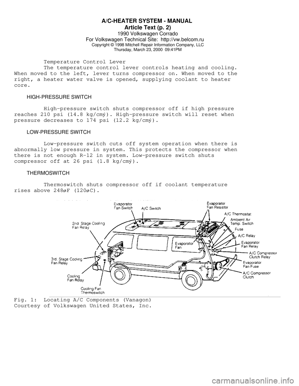
Temperature Control Lever
The temperature control lever controls heating and cooling.
When moved to the left, lever turns compressor on. When moved to the
right, a heater water valve is opened, supplying coolant to heater
core.
HIGH-PRESSURE SWITCH
High-pressure switch shuts compressor off if high pressure
reaches 210 psi (14.8 kg/cmý). High-pressure switch will reset when
pressure decreases to 174 psi (12.2 kg/cm
ý).
LOW-PRESSURE SWITCH
Low-pressure switch cuts off system operation when there is
abnormally low pressure in system. This protects the compressor when
there is not enough R-12 in system. Low-pressure switch shuts
compressor off at 26 psi (1.8 kg/cm
ý).
THERMOSWITCH
Thermoswitch shuts compressor off if coolant temperature
rises above 248
øF (120øC).Fig. 1: Locating A/C Components (Vanagon)
Courtesy of Volkswagen United States, Inc.
Page 380 of 906

ABBREVIATIONS
Article Text (p. 3)
1990 Volkswagen Corrado
For Volkswagen Technical Site: http://vw.belcom.ru
Copyright © 1998 Mitchell Repair Information Company, LLC
Thursday, March 23, 2000 09:42PM³CBVV ³Carburetor Bowl Vent Valve ³
³cc
³Cubic Centimeter ³
³CCC
³Computer Command Control ³
³CCD
³Computer Controlled Dwell ³
³CCM
³Central Control Module ³
³CCO
³Converter Clutch Override ³
³CCOT
³Cycling Clutch Orifice Tube ³
³CCW
³Counterclockwise ³
³CDI
³Capacitor Discharge Ignition ³
³CEC
³Computerized Engine Control ³
³CFI
³Central Fuel Injection ³
³CID
³Cubic Inch Displacement ³
³CID
³Cylinder Identification sensor ³
³CIS
³Continuous Injection System ³
³CIS-E
³Continuous Injection System-Electronic ³
³CKT
³Circuit ³
³CLR
³Clear ³
³CNG
³Compressed Natural Gas ³
³CO
³Carbon Monoxide ³
³CO2
³Carbon Dioxide ³
³CONV
³Convertible ³
³CP
³Canister Purge ³
³CPA
³Connector Position Assurance ³
³CPS
³Crank Position Sensor ³
³CTS
³Coolant Temperature Sensor ³
³CV
³Check Valve or Constant Velocity ³
³CVC
³Constant Vacuum Control ³
³CW
³Clockwise ³
³CYL or Cyl.
³Cylinder ³
³Calif.
³California ³
³Carb.
³Carburetor ³
³Chrg.
³Charging ³
³Circ.
³Circuit ³
³Cntrl.
³Control ³
³Comp.
³Compressor or Compartment ³
³Conn.
³Connector ³
³Cont.
³Continued ³
³Conv.
³Convertible or Converter ³
³Cu. In.
³Cubic Inch ³
³Cyl.
³Cylinder ³
ÀÄÄÄÄÄÄÄÄÄÄÄÄÄÄÄÄÄÁÄÄÄÄÄÄÄÄÄÄÄÄÄÄÄÄÄÄÄÄÄÄÄÄÄÄÄÄÄÄÄÄÄÄÄÄÄÄÄÄÄÄÄÄÄÄÄÄÄÄÙ "D" ABBREVIATION TABLE
"D" ABBREVIATION TABLE
ÚÄÄÄÄÄÄÄÄÄÄÄÄÄÄÄÄÄÂÄÄÄÄÄÄÄÄÄÄÄÄÄÄÄÄÄÄÄÄÄÄÄÄÄÄÄÄÄÄÄÄÄÄÄÄÄÄÄÄÄÄÄÄÄÄÄÄÄÄ¿
³ABBREVIATION
³DEFINITION ³
ÃÄÄÄÄÄÄÄÄÄÄÄÄÄÄÄÄÄÅÄÄÄÄÄÄÄÄÄÄÄÄÄÄÄÄÄÄÄÄÄÄÄÄÄÄÄÄÄÄÄÄÄÄÄÄÄÄÄÄÄÄÄÄÄÄÄÄÄÄ´
³"D"
³Drive ³
³DBC
³Dual Bed Catalyst ³
³DC
³Direct Current or Discharge ³
³DDD
³Dual Diaphragm Distributor ³
Page 381 of 906

ABBREVIATIONS
Article Text (p. 4)
1990 Volkswagen Corrado
For Volkswagen Technical Site: http://vw.belcom.ru
Copyright © 1998 Mitchell Repair Information Company, LLC
Thursday, March 23, 2000 09:42PM³DERM ³Diagnostic Energy Reserve Module ³
³DFI
³Digital Fuel Injection ³
³DIC
³Driver Information Center ³
³DIS
³Direct Ignition System ³
³DIS
³Distributorless Ignition System ³
³DIST
³Distribution ³
³DISTR
³Distributor ³
³DK BLU
³Dark Blue ³
³DK GRN
³Dark Green ³
³DME
³Digital Motor Electronics (Motronic System) ³
³DOHC
³Double Overhead Cam ³
³DOT
³Department of Transportation ³
³DP
³Dashpot ³
³DRB-II
³Diagnostic Readout Box ³
³DVOM
³Digital Volt/Ohm Meter (see VOM) ³
³Def.
³Defogger or Defroster ³
³Def.
³Defrost ³
³Defog.
³Defogger ³
³Diag.
³Diagnostic ³
³Dist.
³Distributor or Distribution ³
³Dr.
³Door ³
ÀÄÄÄÄÄÄÄÄÄÄÄÄÄÄÄÄÄÁÄÄÄÄÄÄÄÄÄÄÄÄÄÄÄÄÄÄÄÄÄÄÄÄÄÄÄÄÄÄÄÄÄÄÄÄÄÄÄÄÄÄÄÄÄÄÄÄÄÄÙ "E" ABBREVIATION TABLE
"E" ABBREVIATION TABLE
ÚÄÄÄÄÄÄÄÄÄÄÄÄÄÄÄÄÄÂÄÄÄÄÄÄÄÄÄÄÄÄÄÄÄÄÄÄÄÄÄÄÄÄÄÄÄÄÄÄÄÄÄÄÄÄÄÄÄÄÄÄÄÄÄÄÄÄÄÄ¿
³ABBREVIATION
³DEFINITION ³
ÃÄÄÄÄÄÄÄÄÄÄÄÄÄÄÄÄÄÅÄÄÄÄÄÄÄÄÄÄÄÄÄÄÄÄÄÄÄÄÄÄÄÄÄÄÄÄÄÄÄÄÄÄÄÄÄÄÄÄÄÄÄÄÄÄÄÄÄÄ´
³EAC
³Electric Assist Choke ³
³EACV
³Electric Air Control Valve ³
³EBCM
³Electronic Brake Control Module ³
³ECA
³Electronic Control Assembly ³
³ECAT
³Electronically Controlled Automatic Transaxle ³
³ECM
³Electronic Control Module ³
³ECT
³Engine Coolant Temperature Sensor ³
³ECU
³Electronic Control Unit or Engine Control Unit ³
³EDF
³Electric Drive Fan relay assembly ³
³EDIS
³Electronic Distributorless Ignition System ³
³EEC
³Electronic Engine Control ³
³EECS
³Evaporative Emission Control System ³
³EEPROM
³Electronically Erasable PROM ³
³EFE
³Early Fuel Evaporation ³
³EFI
³Electronic Fuel Injection ³
³EGO
³Exhaust Gas Oxygen sensor (see HEGO) ³
³EGR
³Exhaust Gas Recirculation system ³
³EGRC
³EGR Control solenoid or system ³
³EGRV
³EGR Vent solenoid or system ³
³EMR
³Emission Maintenance Reminder Module ³
³ESA
³Electronic Spark Advance ³
³ESC
³Electronic Spark Control ³
³EST
³Electronic Spark Timing ³
Page 392 of 906

ABBREVIATIONS
Article Text (p. 3)
1990 Volkswagen Corrado
For Volkswagen Technical Site: http://vw.belcom.ru
Copyright © 1998 Mitchell Repair Information Company, LLC
Thursday, March 23, 2000 09:42PM³CBD ³Closed Bowl Distributor ³
³CBVV
³Carburetor Bowl Vent Valve ³
³cc
³Cubic Centimeter ³
³CCC
³Computer Command Control ³
³CCD
³Computer Controlled Dwell ³
³CCM
³Central Control Module ³
³CCO
³Converter Clutch Override ³
³CCOT
³Cycling Clutch Orifice Tube ³
³CCW
³Counterclockwise ³
³CDI
³Capacitor Discharge Ignition ³
³CEC
³Computerized Engine Control ³
³CFI
³Central Fuel Injection ³
³CID
³Cubic Inch Displacement ³
³CID
³Cylinder Identification sensor ³
³CIS
³Continuous Injection System ³
³CIS-E
³Continuous Injection System-Electronic ³
³CKT
³Circuit ³
³CLR
³Clear ³
³CNG
³Compressed Natural Gas ³
³CO
³Carbon Monoxide ³
³CO2
³Carbon Dioxide ³
³CONV
³Convertible ³
³CP
³Canister Purge ³
³CPA
³Connector Position Assurance ³
³CPS
³Crank Position Sensor ³
³CTS
³Coolant Temperature Sensor ³
³CV
³Check Valve or Constant Velocity ³
³CVC
³Constant Vacuum Control ³
³CW
³Clockwise ³
³CYL or Cyl.
³Cylinder ³
³Calif.
³California ³
³Carb.
³Carburetor ³
³Chrg.
³Charging ³
³Circ.
³Circuit ³
³Cntrl.
³Control ³
³Comp.
³Compressor or Compartment ³
³Conn.
³Connector ³
³Cont.
³Continued ³
³Conv.
³Convertible or Converter ³
³Cu. In.
³Cubic Inch ³
³Cyl.
³Cylinder ³
ÀÄÄÄÄÄÄÄÄÄÄÄÄÄÄÄÄÄÁÄÄÄÄÄÄÄÄÄÄÄÄÄÄÄÄÄÄÄÄÄÄÄÄÄÄÄÄÄÄÄÄÄÄÄÄÄÄÄÄÄÄÄÄÄÄÄÄÄÄÙ "D" ABBREVIATION TABLE
"D" ABBREVIATION TABLE
ÚÄÄÄÄÄÄÄÄÄÄÄÄÄÄÄÄÄÂÄÄÄÄÄÄÄÄÄÄÄÄÄÄÄÄÄÄÄÄÄÄÄÄÄÄÄÄÄÄÄÄÄÄÄÄÄÄÄÄÄÄÄÄÄÄÄÄÄÄ¿
³ABBREVIATION
³DEFINITION ³
ÃÄÄÄÄÄÄÄÄÄÄÄÄÄÄÄÄÄÅÄÄÄÄÄÄÄÄÄÄÄÄÄÄÄÄÄÄÄÄÄÄÄÄÄÄÄÄÄÄÄÄÄÄÄÄÄÄÄÄÄÄÄÄÄÄÄÄÄÄ´
³"D"
³Drive ³
³DBC
³Dual Bed Catalyst ³
³DC
³Direct Current or Discharge ³
Page 393 of 906

ABBREVIATIONS
Article Text (p. 4)
1990 Volkswagen Corrado
For Volkswagen Technical Site: http://vw.belcom.ru
Copyright © 1998 Mitchell Repair Information Company, LLC
Thursday, March 23, 2000 09:42PM³DDD ³Dual Diaphragm Distributor ³
³DERM
³Diagnostic Energy Reserve Module ³
³DFI
³Digital Fuel Injection ³
³DIC
³Driver Information Center ³
³DIS
³Direct Ignition System ³
³DIS
³Distributorless Ignition System ³
³DIST
³Distribution ³
³DISTR
³Distributor ³
³DK BLU
³Dark Blue ³
³DK GRN
³Dark Green ³
³DME
³Digital Motor Electronics (Motronic System) ³
³DOHC
³Double Overhead Cam ³
³DOT
³Department of Transportation ³
³DP
³Dashpot ³
³DRB-II
³Diagnostic Readout Box ³
³DVOM
³Digital Volt/Ohm Meter (see VOM) ³
³Def.
³Defogger or Defroster ³
³Def.
³Defrost ³
³Defog.
³Defogger ³
³Diag.
³Diagnostic ³
³Dist.
³Distributor or Distribution ³
³Dr.
³Door ³
ÀÄÄÄÄÄÄÄÄÄÄÄÄÄÄÄÄÄÁÄÄÄÄÄÄÄÄÄÄÄÄÄÄÄÄÄÄÄÄÄÄÄÄÄÄÄÄÄÄÄÄÄÄÄÄÄÄÄÄÄÄÄÄÄÄÄÄÄÄÙ "E" ABBREVIATION TABLE
"E" ABBREVIATION TABLE
ÚÄÄÄÄÄÄÄÄÄÄÄÄÄÄÄÄÄÂÄÄÄÄÄÄÄÄÄÄÄÄÄÄÄÄÄÄÄÄÄÄÄÄÄÄÄÄÄÄÄÄÄÄÄÄÄÄÄÄÄÄÄÄÄÄÄÄÄÄ¿
³ABBREVIATION
³DEFINITION ³
ÃÄÄÄÄÄÄÄÄÄÄÄÄÄÄÄÄÄÅÄÄÄÄÄÄÄÄÄÄÄÄÄÄÄÄÄÄÄÄÄÄÄÄÄÄÄÄÄÄÄÄÄÄÄÄÄÄÄÄÄÄÄÄÄÄÄÄÄÄ´
³EAC
³Electric Assist Choke ³
³EACV
³Electric Air Control Valve ³
³EBCM
³Electronic Brake Control Module ³
³ECA
³Electronic Control Assembly ³
³ECAT
³Electronically Controlled Automatic Transaxle ³
³ECM
³Electronic Control Module ³
³ECT
³Engine Coolant Temperature Sensor ³
³ECU
³Electronic Control Unit or Engine Control Unit ³
³EDF
³Electric Drive Fan relay assembly ³
³EDIS
³Electronic Distributorless Ignition System ³
³EEC
³Electronic Engine Control ³
³EECS
³Evaporative Emission Control System ³
³EEPROM
³Electronically Erasable PROM ³
³EFE
³Early Fuel Evaporation ³
³EFI
³Electronic Fuel Injection ³
³EGO
³Exhaust Gas Oxygen sensor (see HEGO) ³
³EGR
³Exhaust Gas Recirculation system ³
³EGRC
³EGR Control solenoid or system ³
³EGRV
³EGR Vent solenoid or system ³
³EMR
³Emission Maintenance Reminder Module ³
³ESA
³Electronic Spark Advance ³
³ESC
³Electronic Spark Control ³
Page 440 of 906

D - ADJUSTMENTS
Article Text (p. 3)
1990 Volkswagen Corrado
For Volkswagen Technical Site: http://vw.belcom.ru
Copyright © 1998 Mitchell Repair Information Company, LLC
Thursday, March 23, 2000 09:43PM
NOTE: Mixture adjustment is NOT a part of normal tune-up procedure
and should not be performed unless mixture control unit is
replaced or vehicle fails emissions testing.
NOTE: Ensure system pressure is correct before attempting idle
speed or mixture adjustment.
IDLE SPEED & MIXTURE ADJUSTMENT
FOX (CIS-E) & JETTA GLI 2.0L (CIS-MOTRONIC)
1) Ignition timing and idle speed must be checked before CO
is adjusted. See CHECKING & ADJUSTING under IGNITION TIMING. With
ignition timing properly adjusted, check and adjust idle speed,
differential pressure regulator current and idle mixture. Repeat the
adjustments until all occur at the same time.
2) Warm engine to normal operating temperature. Radiator fan
must come on at least once and engine oil temperature must be at least
176øF (80øC). Turn off all electrical equipment, including A/C and
radiator fan. Disconnect all fuel pressure test equipment (if
installed). If injection lines have been removed or replaced, run
engine several times to 3000 RPM for about 2 minutes.
3) Ensure idle switch is properly adjusted. Check that
auxiliary air regulator valve is fully closed. Pinch shut the hose
leading from the idle speed boost valve(s). Remove temperature sensor
harness connector from the temperature sensor. Pull crankcase breather
hoses off valve cover and air filter, vent to atmosphere.
4) Remove suction hose from carbon canister. Disconnect "T"
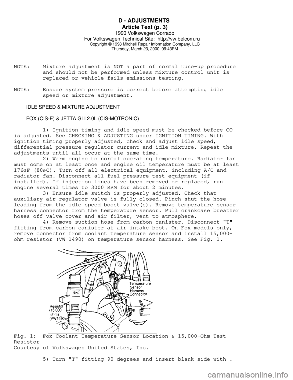
fitting from carbon canister at air intake boot. On Fox models only,
remove connector from coolant temperature sensor and install 15,000-
ohm resistor (VW 1490) on temperature sensor harness. See Fig. 1.Fig. 1: Fox Coolant Temperature Sensor Location & 15,000-Ohm Test
Resistor
Courtesy of Volkswagen United States, Inc.
5) Turn "T" fitting 90 degrees and insert blank side with .
Page 443 of 906

D - ADJUSTMENTS
Article Text (p. 6)
1990 Volkswagen Corrado
For Volkswagen Technical Site: http://vw.belcom.ru
Copyright © 1998 Mitchell Repair Information Company, LLC
Thursday, March 23, 2000 09:43PM
NOTE: Before checking engine timing, raise engine speed above 2100
RPM at least 4 times. This must be done each time ignition
is turned off and restarted to clear ECU memory and by-pass
hot-start, fast-idle function.
3) Connect an inductive tachometer or Tester (VW 1367) to
alternator, Test Lead (VW 1473) to ignition coil, and timing light
lead to No. 1 spark plug wire. See Fig. 2. Start engine and ensure
engine speed and timing are correct. If not, adjust to specification.
4) Remove the Blue cap from the CO tap tube rising from the
exhaust manifold and connect exhaust gas analyzer. Disconnect the
coolant sensor harness connector. Raise the oil dipstick slightly to
vent crankcase. Disconnect and plug the crankcase ventilation hose.
Start engine and raise engine speed to 2100 RPM at least 4 times.
Check idle, adjust if incorrect. check CO is correct. See IDLE & CO
LEVEL table. If CO adjustment is needed, the idle mixture screw anti-
tamper plug must be remove from the top of the air flow sensor.
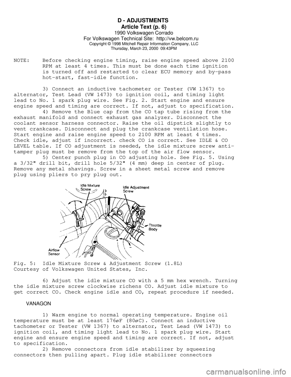
5) Center punch plug in CO adjusting hole. See Fig. 5. Using
a 3/32" drill bit, drill hole 5/32" (4 mm) deep in center of plug.
Remove any metal shavings. Screw in a sheet metal screw and remove
plug using pliers to pry plug out.Fig. 5: Idle Mixture Screw & Adjustment Screw (1.8L)
Courtesy of Volkswagen United States, Inc.
6) Adjust the idle mixture CO with a 5 mm hex wrench. Turning
the idle mixture screw clockwise richens CO. Adjust idle mixture to
get correct CO. Check engine idle and CO, repeat procedure if needed.
VANAGON
1) Warm engine to normal operating temperature. Engine oil
temperature must be at least 176øF (80øC). Connect an inductive
tachometer or Tester (VW 1367) to alternator, Test Lead (VW 1473) to
ignition coil, and timing light lead to No. 1 spark plug wire. Start
engine and ensure engine speed and timing are correct. If not, adjust
to specification.
2) Remove connectors from idle stabilizer by squeezing
connectors then pulling apart. Plug idle stabilizer connectors