1990 VOLKSWAGEN CORRADO differential
[x] Cancel search: differentialPage 54 of 906

* BRAKE SYSTEM UNIFORM INSPECTION GUIDELINES *
Article Text (p. 22)
1990 Volkswagen Corrado
For Volkswagen Technical Site: http://vw.belcom.ru
Copyright © 1998 Mitchell Repair Information Company, LLC
Thursday, March 23, 2000 09:29PMÄÄÄÄÄÄÄÄÄÄÄÄÄÄÄÄÄÄÄÄÄÄÄÄÄÄÄÅÄÄÄÄÄÄÅÄÄÄÄÄÄÄÄÄÄÄÄÄÄÄÄÄÄÄÄÄÄÄÄÄÄÄÄÄÄÄÄÄÄÄParking brake parts are
³ A ³ Require replacement of broken
broken
³ ³ parts.
ÄÄÄÄÄÄÄÄÄÄÄÄÄÄÄÄÄÄÄÄÄÄÄÄÄÄÄÅÄÄÄÄÄÄÅÄÄÄÄÄÄÄÄÄÄÄÄÄÄÄÄÄÄÄÄÄÄÄÄÄÄÄÄÄÄÄÄÄÄÄParking brake parts bent
³ A ³ Require replacement of bent parts.
ÄÄÄÄÄÄÄÄÄÄÄÄÄÄÄÄÄÄÄÄÄÄÄÄÄÄÄÁÄÄÄÄÄÄÁÄÄÄÄÄÄÄÄÄÄÄÄÄÄÄÄÄÄÄÄÄÄÄÄÄÄÄÄÄÄÄÄÄÄÄ PEDAL TRAVEL SWITCHES
PEDAL TRAVEL SWITCHES
ÄÄÄÄÄÄÄÄÄÄÄÄÄÄÄÄÄÄÄÄÄÄÄÄÄÄÄÂÄÄÄÄÄÄÂÄÄÄÄÄÄÄÄÄÄÄÄÄÄÄÄÄÄÄÄÄÄÄÄÄÄÄÄÄÄÄÄÄÄÄCondition
³ Code ³ Procedure
ÄÄÄÄÄÄÄÄÄÄÄÄÄÄÄÄÄÄÄÄÄÄÄÄÄÄÄÅÄÄÄÄÄÄÅÄÄÄÄÄÄÄÄÄÄÄÄÄÄÄÄÄÄÄÄÄÄÄÄÄÄÄÄÄÄÄÄÄÄÄBent
³ A ³ Require replacement.
ÄÄÄÄÄÄÄÄÄÄÄÄÄÄÄÄÄÄÄÄÄÄÄÄÄÄÄÅÄÄÄÄÄÄÅÄÄÄÄÄÄÄÄÄÄÄÄÄÄÄÄÄÄÄÄÄÄÄÄÄÄÄÄÄÄÄÄÄÄÄBroken
³ A ³ Require replacement.
ÄÄÄÄÄÄÄÄÄÄÄÄÄÄÄÄÄÄÄÄÄÄÄÄÄÄÄÅÄÄÄÄÄÄÅÄÄÄÄÄÄÄÄÄÄÄÄÄÄÄÄÄÄÄÄÄÄÄÄÄÄÄÄÄÄÄÄÄÄÄCorroded
³ B,2 ³ Suggest repair or replacement.
ÄÄÄÄÄÄÄÄÄÄÄÄÄÄÄÄÄÄÄÄÄÄÄÄÄÄÄÅÄÄÄÄÄÄÅÄÄÄÄÄÄÄÄÄÄÄÄÄÄÄÄÄÄÄÄÄÄÄÄÄÄÄÄÄÄÄÄÄÄÄMissing
³ A ³ Require replacement.
ÄÄÄÄÄÄÄÄÄÄÄÄÄÄÄÄÄÄÄÄÄÄÄÄÄÄÄÅÄÄÄÄÄÄÅÄÄÄÄÄÄÄÄÄÄÄÄÄÄÄÄÄÄÄÄÄÄÄÄÄÄÄÄÄÄÄÄÄÄÄOut of adjustment
³ A ³ Require adjustment or replacement.
ÄÄÄÄÄÄÄÄÄÄÄÄÄÄÄÄÄÄÄÄÄÄÄÄÄÄÄÅÄÄÄÄÄÄÅÄÄÄÄÄÄÄÄÄÄÄÄÄÄÄÄÄÄÄÄÄÄÄÄÄÄÄÄÄÄÄÄÄÄÄOutput signal incorrect
³ A ³ Require replacement.
ÄÄÄÄÄÄÄÄÄÄÄÄÄÄÄÄÄÄÄÄÄÄÄÄÄÄÄÁÄÄÄÄÄÄÁÄÄÄÄÄÄÄÄÄÄÄÄÄÄÄÄÄÄÄÄÄÄÄÄÄÄÄÄÄÄÄÄÄÄÄ PRESSURE DIFFERENTIAL SWITCHES
PRESSURE DIFFERENTIAL SWITCHES
ÄÄÄÄÄÄÄÄÄÄÄÄÄÄÄÄÄÄÄÄÄÄÄÄÄÄÄÂÄÄÄÄÄÄÂÄÄÄÄÄÄÄÄÄÄÄÄÄÄÄÄÄÄÄÄÄÄÄÄÄÄÄÄÄÄÄÄÄÄÄCondition
³ Code ³ Procedure
ÄÄÄÄÄÄÄÄÄÄÄÄÄÄÄÄÄÄÄÄÄÄÄÄÄÄÄÅÄÄÄÄÄÄÅÄÄÄÄÄÄÄÄÄÄÄÄÄÄÄÄÄÄÄÄÄÄÄÄÄÄÄÄÄÄÄÄÄÄÄBent
³ A ³ Require replacement.
ÄÄÄÄÄÄÄÄÄÄÄÄÄÄÄÄÄÄÄÄÄÄÄÄÄÄÄÅÄÄÄÄÄÄÅÄÄÄÄÄÄÄÄÄÄÄÄÄÄÄÄÄÄÄÄÄÄÄÄÄÄÄÄÄÄÄÄÄÄÄBroken
³ A ³ Require replacement.
ÄÄÄÄÄÄÄÄÄÄÄÄÄÄÄÄÄÄÄÄÄÄÄÄÄÄÄÅÄÄÄÄÄÄÅÄÄÄÄÄÄÄÄÄÄÄÄÄÄÄÄÄÄÄÄÄÄÄÄÄÄÄÄÄÄÄÄÄÄÄCorroded
³ B,2 ³ Suggest repair or replacement.
ÄÄÄÄÄÄÄÄÄÄÄÄÄÄÄÄÄÄÄÄÄÄÄÄÄÄÄÅÄÄÄÄÄÄÅÄÄÄÄÄÄÄÄÄÄÄÄÄÄÄÄÄÄÄÄÄÄÄÄÄÄÄÄÄÄÄÄÄÄÄMissing
³ A ³ Require replacement.
ÄÄÄÄÄÄÄÄÄÄÄÄÄÄÄÄÄÄÄÄÄÄÄÄÄÄÄÅÄÄÄÄÄÄÅÄÄÄÄÄÄÄÄÄÄÄÄÄÄÄÄÄÄÄÄÄÄÄÄÄÄÄÄÄÄÄÄÄÄÄOutput signal incorrect
³ A ³ Require replacement.
ÄÄÄÄÄÄÄÄÄÄÄÄÄÄÄÄÄÄÄÄÄÄÄÄÄÄÄÅÄÄÄÄÄÄÅÄÄÄÄÄÄÄÄÄÄÄÄÄÄÄÄÄÄÄÄÄÄÄÄÄÄÄÄÄÄÄÄÄÄÄLeaking
³ A ³ Require repair or replacement.
ÄÄÄÄÄÄÄÄÄÄÄÄÄÄÄÄÄÄÄÄÄÄÄÄÄÄÄÁÄÄÄÄÄÄÁÄÄÄÄÄÄÄÄÄÄÄÄÄÄÄÄÄÄÄÄÄÄÄÄÄÄÄÄÄÄÄÄÄÄÄ PRESSURE SWITCHES
PRESSURE SWITCHES
ÄÄÄÄÄÄÄÄÄÄÄÄÄÄÄÄÄÄÄÄÄÄÄÄÄÄÄÂÄÄÄÄÄÄÂÄÄÄÄÄÄÄÄÄÄÄÄÄÄÄÄÄÄÄÄÄÄÄÄÄÄÄÄÄÄÄÄÄÄÄCondition
³ Code ³ Procedure
ÄÄÄÄÄÄÄÄÄÄÄÄÄÄÄÄÄÄÄÄÄÄÄÄÄÄÄÅÄÄÄÄÄÄÅÄÄÄÄÄÄÄÄÄÄÄÄÄÄÄÄÄÄÄÄÄÄÄÄÄÄÄÄÄÄÄÄÄÄÄConnector loose
³ A ³ Require repair or replacement.
Page 440 of 906
D - ADJUSTMENTS
Article Text (p. 3)
1990 Volkswagen Corrado
For Volkswagen Technical Site: http://vw.belcom.ru
Copyright © 1998 Mitchell Repair Information Company, LLC
Thursday, March 23, 2000 09:43PM
NOTE: Mixture adjustment is NOT a part of normal tune-up procedure
and should not be performed unless mixture control unit is
replaced or vehicle fails emissions testing.
NOTE: Ensure system pressure is correct before attempting idle
speed or mixture adjustment.
IDLE SPEED & MIXTURE ADJUSTMENT
FOX (CIS-E) & JETTA GLI 2.0L (CIS-MOTRONIC)
1) Ignition timing and idle speed must be checked before CO
is adjusted. See CHECKING & ADJUSTING under IGNITION TIMING. With
ignition timing properly adjusted, check and adjust idle speed,
differential pressure regulator current and idle mixture. Repeat the
adjustments until all occur at the same time.
2) Warm engine to normal operating temperature. Radiator fan
must come on at least once and engine oil temperature must be at least
176øF (80øC). Turn off all electrical equipment, including A/C and
radiator fan. Disconnect all fuel pressure test equipment (if
installed). If injection lines have been removed or replaced, run
engine several times to 3000 RPM for about 2 minutes.
3) Ensure idle switch is properly adjusted. Check that
auxiliary air regulator valve is fully closed. Pinch shut the hose
leading from the idle speed boost valve(s). Remove temperature sensor
harness connector from the temperature sensor. Pull crankcase breather
hoses off valve cover and air filter, vent to atmosphere.
4) Remove suction hose from carbon canister. Disconnect "T"
fitting from carbon canister at air intake boot. On Fox models only,
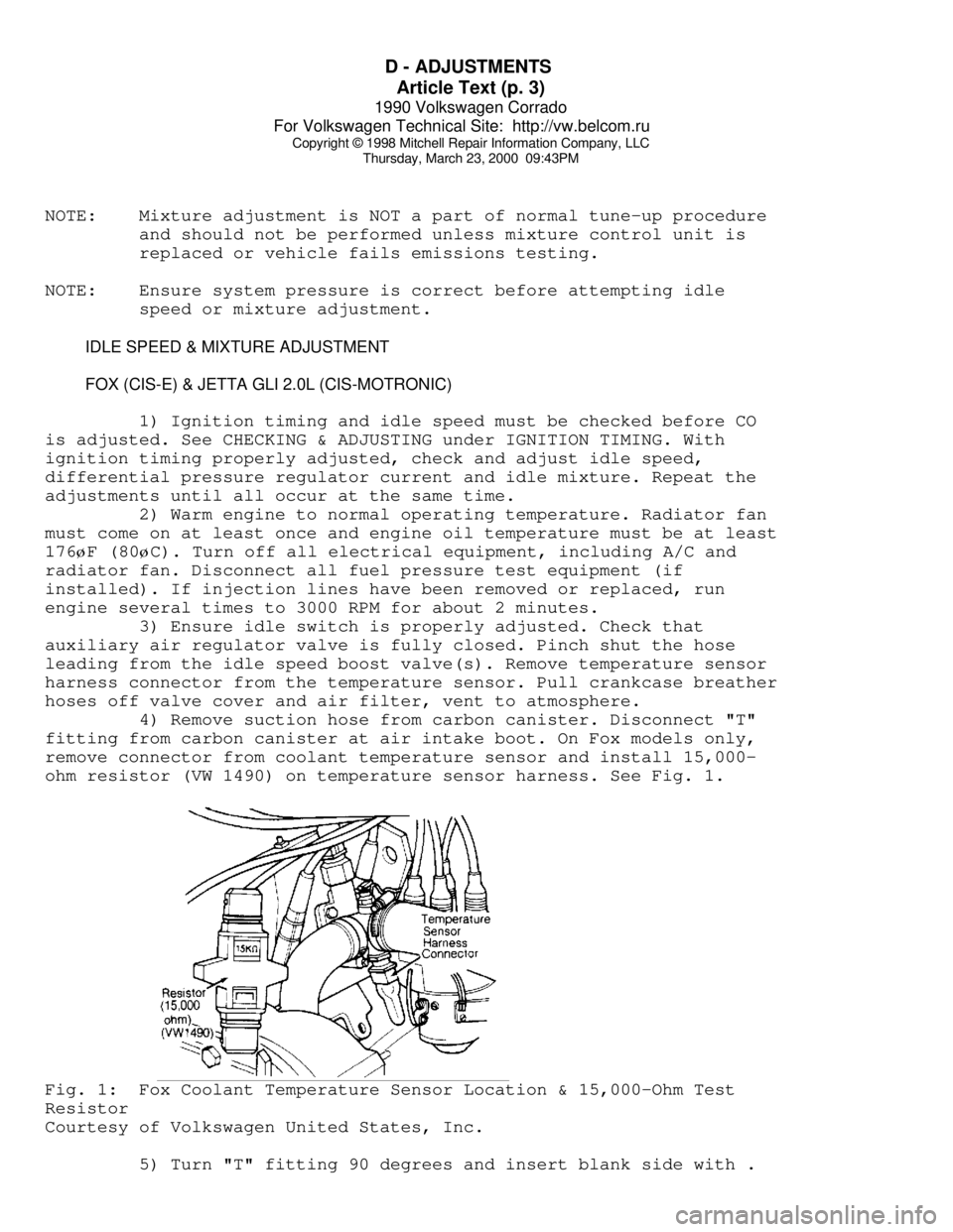
remove connector from coolant temperature sensor and install 15,000-
ohm resistor (VW 1490) on temperature sensor harness. See Fig. 1.Fig. 1: Fox Coolant Temperature Sensor Location & 15,000-Ohm Test
Resistor
Courtesy of Volkswagen United States, Inc.
5) Turn "T" fitting 90 degrees and insert blank side with .
Page 441 of 906
D - ADJUSTMENTS
Article Text (p. 4)
1990 Volkswagen Corrado
For Volkswagen Technical Site: http://vw.belcom.ru
Copyright © 1998 Mitchell Repair Information Company, LLC
Thursday, March 23, 2000 09:43PM
059" (1.5 mm) restrictor into hole in intake air boot. If vehicle is
not equipped with this type of connector, use Plug (026 133 382D) with
.059" (1.5 mm) orifice. Adjust idle speed if not within specification.
See IDLE SPEED & CO LEVEL table.
6) Connect fuel pressure gauge and ensure system fuel
pressure is correct. See FUEL SYSTEM in F - BASIC TESTING article.
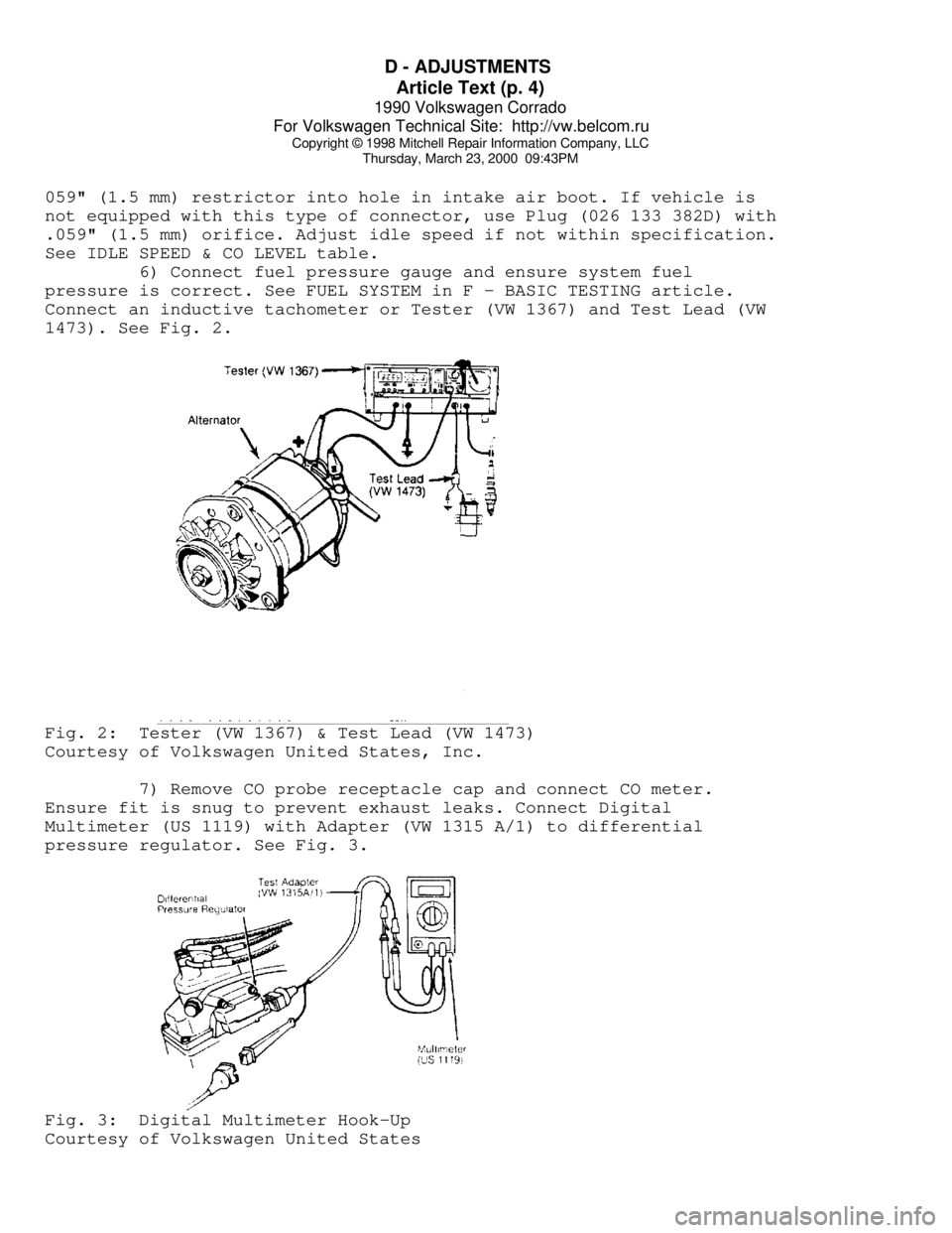
Connect an inductive tachometer or Tester (VW 1367) and Test Lead (VW
1473). See Fig. 2.Fig. 2: Tester (VW 1367) & Test Lead (VW 1473)
Courtesy of Volkswagen United States, Inc.
7) Remove CO probe receptacle cap and connect CO meter.
Ensure fit is snug to prevent exhaust leaks. Connect Digital
Multimeter (US 1119) with Adapter (VW 1315 A/1) to differential
pressure regulator. See Fig. 3.Fig. 3: Digital Multimeter Hook-Up
Courtesy of Volkswagen United States
Page 449 of 906
DRIVE AXLE - GEAR TOOTH CONTACT PATTERNS
Article Text (p. 2)
1990 Volkswagen Corrado
For Volkswagen Technical Site: http://vw.belcom.ru
Copyright © 1998 Mitchell Repair Information Company, LLC
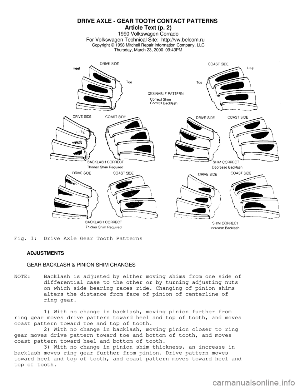
Thursday, March 23, 2000 09:43PMFig. 1: Drive Axle Gear Tooth Patterns
ADJUSTMENTS
GEAR BACKLASH & PINION SHIM CHANGES
NOTE: Backlash is adjusted by either moving shims from one side of
differential case to the other or by turning adjusting nuts
on which side bearing races ride. Changing of pinion shims
alters the distance from face of pinion of centerline of
ring gear.
1) With no change in backlash, moving pinion further from
ring gear moves drive pattern toward heel and top of tooth, and moves
coast pattern toward toe and top of tooth.
2) With no change in backlash, moving pinion closer to ring
gear moves drive pattern toward toe and bottom of tooth, and moves
coast pattern toward heel and bottom of tooth.
3) With no change in pinion shim thickness, an increase in
backlash moves ring gear further from pinion. Drive pattern moves
toward heel and top of tooth, and coast pattern moves toward heel and
top of tooth.
Page 456 of 906

E - THEORY/OPERATION - DIGIFANT
Article Text (p. 6)
1990 Volkswagen Corrado
For Volkswagen Technical Site: http://vw.belcom.ru
Copyright © 1998 Mitchell Repair Information Company, LLC
Thursday, March 23, 2000 09:43PM
element and the power steering pressure switch.
FUEL PRESSURE REGULATOR
The fuel pressure regulator is a sealed, spring loaded
diaphragm with connection for intake manifold vacuum. Fuel pressure is
maintained at about 36 psi (2.5 kg/cmý) pressure.
A connection for intake manifold vacuum provides a constant
pressure differential which ensures that the amount of fuel injected
is solely dependent upon injector open ON time. Excess fuel is
returned to fuel tank. No service of pressure regulator is required.
The pressure regulator is located on or near fuel rail.
FUEL CONTROL
Data on engine temperature, engine speed, intake air volume,
throttle position, exhaust oxygen content and intake air temperature
are used by ECM to determine injection pulse width.
FUEL INJECTORS
A fuel rail links the fuel pressure regulator with the fuel
injectors. Each cylinder is provided with a solenoid-operated injector
which sprays fuel toward backside of each inlet valve. Each injector
is energized through the ignition coil and grounded through the ECU to
complete the circuit
Each injector is linked to a resistor (resistor may be
external or integral with injector or ECU) to reduce operating voltage
to 3 volts and to protect injectors from power surges. The ECU
controls length of time each injector is open. The ON time of the
injector governs the amount of fuel delivered. The injector delivers
1/2 the amount of fuel required for an operating cycle each time they
open (twice per cycle).
FUEL PUMP AFTER-RUN RELAY (CORRADO)
The purpose of the After-Run Fuel Pump relay system is to
reduce the chance of fuel vaporizing in fuel rail. Both transfer pump
and fuel pump are used to recirculate fuel. The after-run relay
switches the pumps on for 2 minutes after ignition is turned off or
when under hood temperature exceeds 194
ø F (90ø C) and fuel pressure
is above 17 psi (1.2 kg/cm
ý). The pumps operate a maximum of 8
minutes.
IDLE SPEED
Engine idle speed is controlled by the ECU and idle speed
control unit depending upon engine operating conditions. The ECU and
Idle speed control unit are fed information on engine operating
conditions and determine the best idle speed.
IDLE AIR STABILIZER VALVE
Page 521 of 906
ENGINE OVERHAUL PROCEDURES - GENERAL INFORMATION
Article Text (p. 12)
1990 Volkswagen Corrado
For Volkswagen Technical Site: http://vw.belcom.ru
Copyright © 1998 Mitchell Repair Information Company, LLC
Thursday, March 23, 2000 09:44PM
Valve Seat Replacement
Replacement of valve seat inserts is done by cutting out
the old insert and machining an oversize insert bore. Replacement
oversize insert is usually chilled and the cylinder head is sometimes
warmed. Valve seat is pressed into the head. This operation requires
specialized machine shop equipment.
Valve Seat Concentricity
Using dial gauge, install gauge pilot in valve guide.
Position gauge arm on the valve seat. Adjust dial indicator to zero.
Rotate arm 360 degrees and note reading. Runout should not exceed
specification.
To check valve-to-valve seat concentricity, coat valve face
lightly with Prussian Blue dye. Install valve and rotate it on valve
seat. If pattern is even and entire seat is coated at valve contact
point, valve is concentric with the seat.
REASSEMBLY
Valve Stem Installed Height
Valve stem installed height must be checked when new valves
are installed or when valves or valve seats have been ground. Install
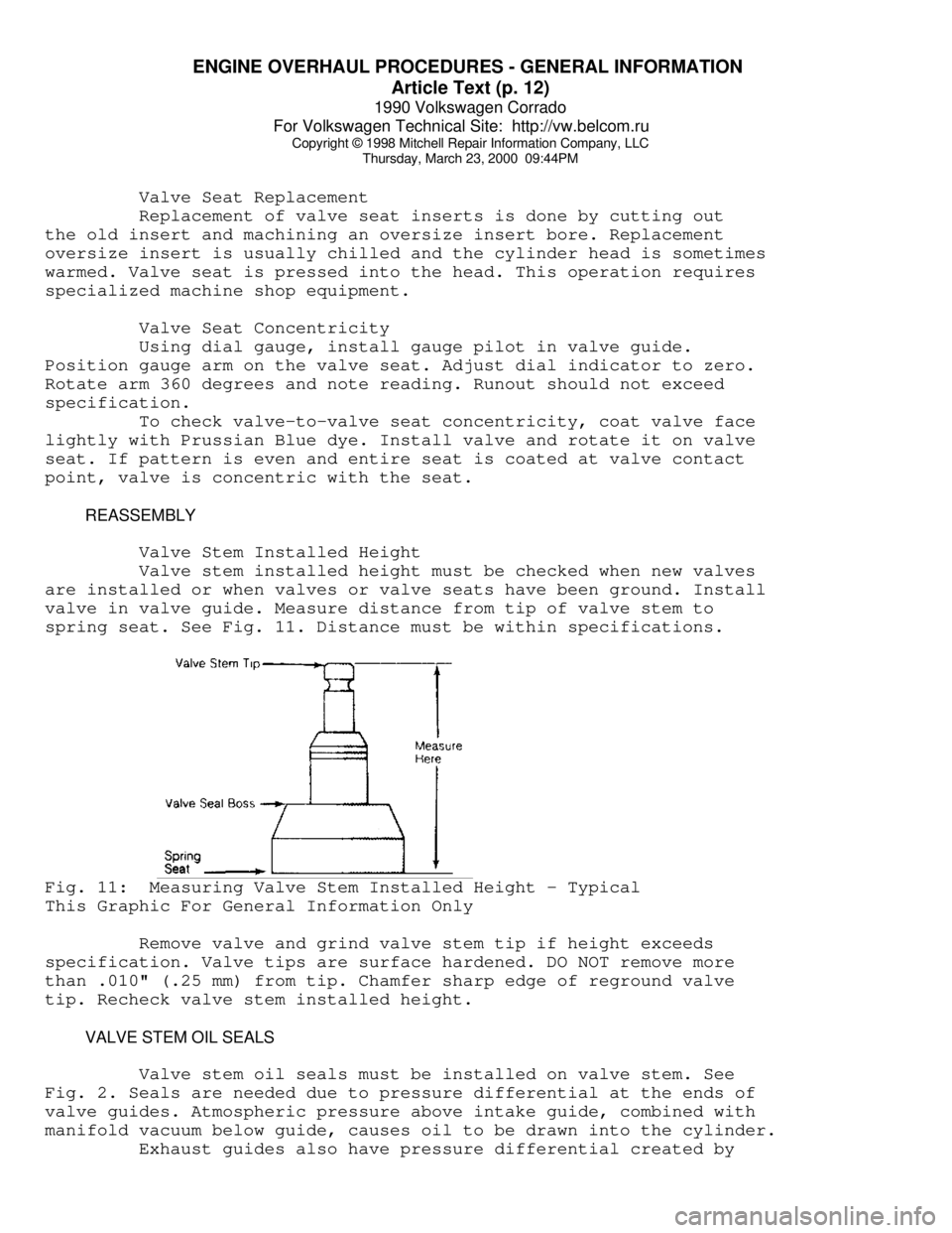
valve in valve guide. Measure distance from tip of valve stem to
spring seat. See Fig. 11. Distance must be within specifications.Fig. 11: Measuring Valve Stem Installed Height - Typical
This Graphic For General Information Only
Remove valve and grind valve stem tip if height exceeds
specification. Valve tips are surface hardened. DO NOT remove more
than .010" (.25 mm) from tip. Chamfer sharp edge of reground valve
tip. Recheck valve stem installed height.
VALVE STEM OIL SEALS
Valve stem oil seals must be installed on valve stem. See
Fig. 2. Seals are needed due to pressure differential at the ends of
valve guides. Atmospheric pressure above intake guide, combined with
manifold vacuum below guide, causes oil to be drawn into the cylinder.
Exhaust guides also have pressure differential created by
Page 569 of 906
GEAR TOOTH CONTACT PATTERNS
Article Text (p. 2)
1990 Volkswagen Corrado
For Volkswagen Technical Site: http://vw.belcom.ru
Copyright © 1998 Mitchell Repair Information Company, LLC
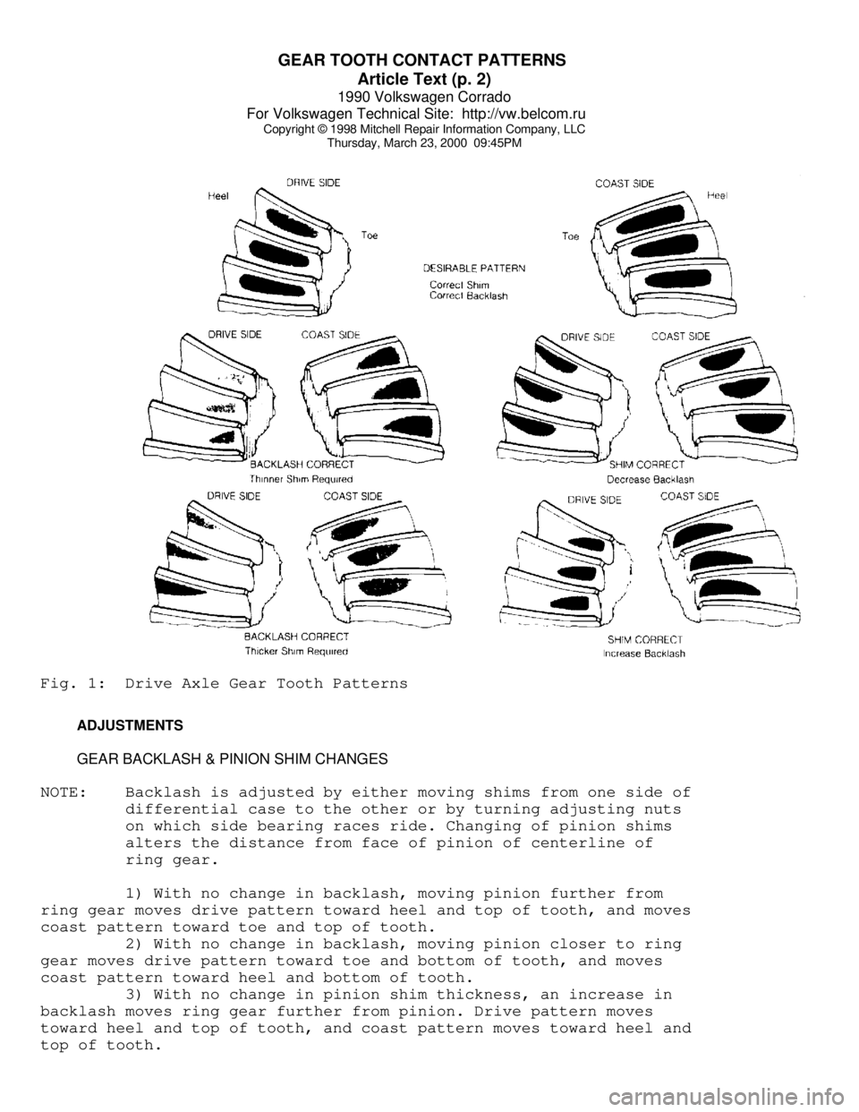
Thursday, March 23, 2000 09:45PMFig. 1: Drive Axle Gear Tooth Patterns
ADJUSTMENTS
GEAR BACKLASH & PINION SHIM CHANGES
NOTE: Backlash is adjusted by either moving shims from one side of
differential case to the other or by turning adjusting nuts
on which side bearing races ride. Changing of pinion shims
alters the distance from face of pinion of centerline of
ring gear.
1) With no change in backlash, moving pinion further from
ring gear moves drive pattern toward heel and top of tooth, and moves
coast pattern toward toe and top of tooth.
2) With no change in backlash, moving pinion closer to ring
gear moves drive pattern toward toe and bottom of tooth, and moves
coast pattern toward heel and bottom of tooth.
3) With no change in pinion shim thickness, an increase in
backlash moves ring gear further from pinion. Drive pattern moves
toward heel and top of tooth, and coast pattern moves toward heel and
top of tooth.
Page 592 of 906
I - SYSTEM/COMPONENT TESTS
Article Text (p. 5)
1990 Volkswagen Corrado
For Volkswagen Technical Site: http://vw.belcom.ru
Copyright © 1998 Mitchell Repair Information Company, LLC
Thursday, March 23, 2000 09:46PM
COOLANT TEMPERATURE SENSOR
Turn ignition off. Use a thermometer to measure coolant
temperature. Unplug connector from Electronic Control Unit (ECU).
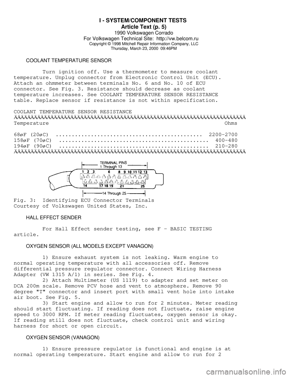
Attach an ohmmeter between terminals No. 6 and No. 10 of ECU
connector. See Fig. 3. Resistance should decrease as coolant
temperature increases. See COOLANT TEMPERATURE SENSOR RESISTANCE
table. Replace sensor if resistance is not within specification.
COOLANT TEMPERATURE SENSOR RESISTANCEÄÄÄÄÄÄÄÄÄÄÄÄÄÄÄÄÄÄÄÄÄÄÄÄÄÄÄÄÄÄÄÄÄÄÄÄÄÄÄÄÄÄÄÄÄÄÄÄÄÄÄÄÄÄÄÄÄÄÄÄÄÄÄÄÄÄÄÄÄÄTemperature Ohms
68
øF (20øC) .............................................. 2200-2700
158
øF (70øC) ............................................... 400-480
194
øF (90øC) ............................................... 210-280
ÄÄÄÄÄÄÄÄÄÄÄÄÄÄÄÄÄÄÄÄÄÄÄÄÄÄÄÄÄÄÄÄÄÄÄÄÄÄÄÄÄÄÄÄÄÄÄÄÄÄÄÄÄÄÄÄÄÄÄÄÄÄÄÄÄÄÄÄÄÄFig. 3: Identifying ECU Connector Terminals
Courtesy of Volkswagen United States, Inc.
HALL EFFECT SENDER
For Hall Effect sender testing, see F - BASIC TESTING
article.
OXYGEN SENSOR (ALL MODELS EXCEPT VANAGON)
1) Ensure exhaust system is not leaking. Warm engine to
normal operating temperature with all accessories off. Remove
differential pressure regulator connector. Connect Wiring Harness
Adapter (VW 1315 A/1) in series. See Fig. 4.
2) Attach Multimeter (US 1119) to adapter and set meter on
DCA 200m scale. Remove PCV hose and vent to atmosphere. Remove 90
degree "T" connector and insert port with small vent hole into intake
air boot. See Fig. 5.
3) Start engine and allow to run for 2 minutes. Meter reading
should start fluctuating. If reading does not fluctuate, raise engine
speed to 3000 RPM. If meter reading fluctuates, oxygen sensor is okay.
If reading still does not fluctuate, check control unit and wiring
harness for short or open circuit.
OXYGEN SENSOR (VANAGON)
1) Ensure pressure regulator is functional and engine is at
normal operating temperature. Start engine and allow to run for 2