1990 VOLKSWAGEN CORRADO radio
[x] Cancel search: radioPage 288 of 906
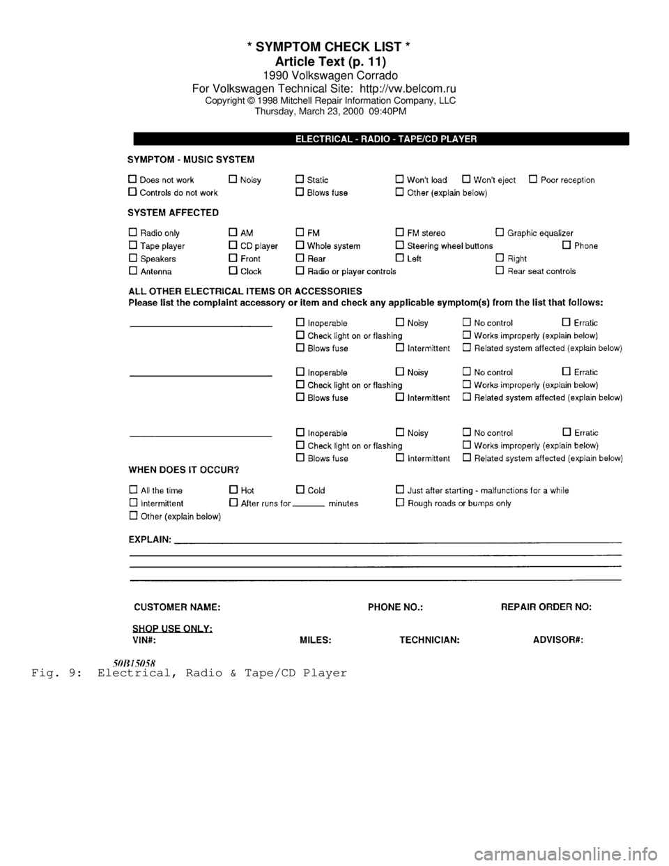
* SYMPTOM CHECK LIST *
Article Text (p. 11)
1990 Volkswagen Corrado
For Volkswagen Technical Site: http://vw.belcom.ru
Copyright © 1998 Mitchell Repair Information Company, LLC
Thursday, March 23, 2000 09:40PMFig. 9: Electrical, Radio & Tape/CD Player
Page 564 of 906

FUSES & CIRCUIT BREAKERS
Article Text (p. 2)
1990 Volkswagen Corrado
For Volkswagen Technical Site: http://vw.belcom.ru
Copyright © 1998 Mitchell Repair Information Company, LLC
Thursday, March 23, 2000 09:45PM
Right Tail & Side Lights
8 - 10 Amp
Left Tail & Side Lights
9 - 20 Amp
Rear Window & Mirror Heating
10 - 15 Amp
Foglights
11 - 10 Amp
Left High Beam, High Beam Indicator
12 - 10 Amp
Right High Beam
13 - 10 Amp
Horn, Radiator Fan
14 - 15 Amp
Back-Up Lights, Electric Mirrors, Heated Windshield Washer
Jets
15 - 10 Amp
Engine Electronic
16 - 15 Amp
Warning/Indicator Lights, Multi-Function Indicator, Glove Box
Light, Cassette Storage Light, Rear Spoiler
17 - 10 Amp
Turn Signals
18 - 20 Amp
Fuel Pump, Oxygen Sensor
19 - 30 Amp
Radiator Fan, Air Conditioner
20 - 10 Amp
Brakelights, Cruise Control
21 - 15 Amp
Dome & Luggage Compartment Lights, Cigarette Lighter, Central
Locking System, Multi-Function Indicator
22 - 10 Amp
Radio
CAUTIONS & WARNINGS
ELECTRICAL SHOCK
WARNING: Contact with live components of ignition system while
engine is running could lead to a fatal electric shock.
RADIATOR FAN
Keep hands away from radiator fan. Fan is controlled by a
thermostatic switch which may come on or run for up to 15 minutes even
after engine is turned off.
RADIATOR CAP
CAUTION: Always disconnect the fan motor when working near the
radiator fan. The fan is temperature controlled and could
Page 566 of 906

FUSES & CIRCUIT BREAKERS
Article Text (p. 4)
1990 Volkswagen Corrado
For Volkswagen Technical Site: http://vw.belcom.ru
Copyright © 1998 Mitchell Repair Information Company, LLC
Thursday, March 23, 2000 09:45PM
position from passenger's side of vehicle in case of
accidental air bag inflation
ANTI-LOCK BRAKE SYSTEM
The anti-lock brake system contains electronic equipment that
can be susceptible to interference caused by improperly installed or
high output radio transmitting equipment. Since this interference
could cause the possible loss of the anti-lock braking capability,
such equipment should be installed by qualified professionals.
CATALYTIC CONVERTER
To prevent catalytic converter overheating, DO NOT allow
engine to idle for more than 20 minutes.
END OF ARTICLE
Page 585 of 906
HEATER SYSTEM
Article Text (p. 5)
1990 Volkswagen Corrado
For Volkswagen Technical Site: http://vw.belcom.ru
Copyright © 1998 Mitchell Repair Information Company, LLC
Thursday, March 23, 2000 09:45PM
retaining screws. Remove lower left instrument panel. Remove lower
right instrument panel tray retaining screws.
2) Remove lower right instrument panel. Remove gearshift
lever knob. Remove gearshift lever boot. Remove center console
retaining screws. Slide center console rearward. Disconnect electrical
connectors attached to center console. Remove center console.
3) Remove temperature control knobs. Remove trim plate.
Remove radio. Remove switches from instrument panel. Remove instrument
panel trim plate retaining screws. Remove instrument panel trim plate.
Remove instrument cluster retaining screws. Remove instrument cluster.
4) Disconnect speedometer cable, electrical connectors and
vacuum hoses from instrument cluster. Remove speaker grilles. Remove
air outlet grilles from housings. Remove housing retaining screws.
Remove air outlet housings. Remove instrument panel mounting nuts and
screws.
5) Remove instrument panel. Disconnect heater hoses from
heater core. Remove heater assembly mounting bolts and nuts. Remove
all attaching ducts. Disconnect cables from heater assembly. Remove
heater assembly.
INSTALLATION
Reverse removal procedure for installation. Fill radiator
with coolant and start engine. Ensure heater control is in warm
position to purge air from heater core.
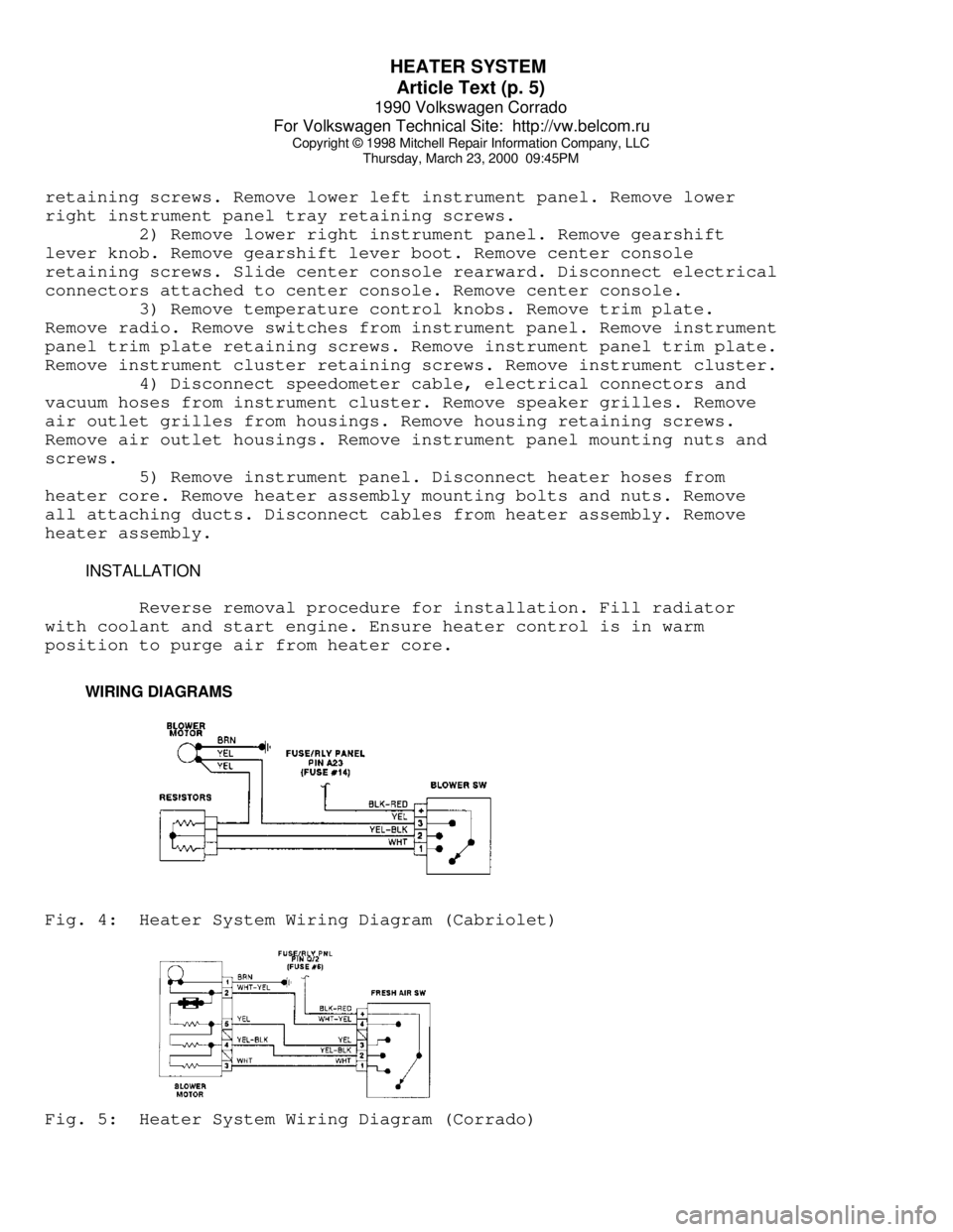
WIRING DIAGRAMSFig. 4: Heater System Wiring Diagram (Cabriolet)Fig. 5: Heater System Wiring Diagram (Corrado)
Page 605 of 906

INSTRUMENT PANEL
Article Text (p. 3)
1990 Volkswagen Corrado
For Volkswagen Technical Site: http://vw.belcom.ru
Copyright © 1998 Mitchell Repair Information Company, LLC
Thursday, March 23, 2000 09:46PM
Removal & Installation
Disconnect negative battery cable. Remove steering wheel.
Pull tilt shelf downward. Remove 3 shelf retaining screws and remove
shelf. Remove 3 instrument panel lower retaining screws and and pry
off 3 clips. Remove 2 instrument trim retaining screws and remove
instrument panel trim. Remove center instrument cluster screw and tip
instrument panel cluster forward. Remove speedometer cable and wiring
connector from back of cluster. Remove instrument panel cluster. To
install, reverse removal procedure.
INSTRUMENT CLUSTER - FOX
Removal & Installation
Disconnect negative battery cable. Remove steering wheel.
Carefully remove covers from vacant switch position. Depress switch
spring retainer and remove switches from instrument panel. Disconnect
wire connectors from switches. Remove 4 instrument cluster trim
retaining screws. Remove instrument cluster trim panel. Remove 2
instrument cluster retaining screws. Remove speedometer cable.
Disconnect cluster wire connector and remove instrument cluster. To
install, reverse removal procedure.
INSTRUMENT CLUSTER - GOLF, GTI, JETTA & JETTA GLI
Removal & Installation
Remove temperature control knobs, levers and trim plate.
Remove radio or convenience tray. Remove switches from instrument
panel trim plate. Remove instrument panel trim plate. Remove 2
mounting screws and pull instrument cluster outward. Remove
speedometer cable, vacuum hoses, and electrical connections. To
install, reverse removal procedures.
INSTRUMENT CLUSTER - VANAGON
Removal & Installation
Disconnect negative battery cable. Reach behind cluster hood
and pull back of hood upward. Pull hazard switch forward. Pull brake
warning light housing toward front of vehicle. Remove 4 mounting
screws and remove cluster. To install, reverse removal procedure.
COMBINATION SWITCH
Removal
Remove steering wheel. Remove column cover. Disconnect wiring
and remove 3 switch screws. Remove switches.
Installation
Install switches on column. Place steering wheel on column
and ensure clearance between wheel and turn signal switch is 1/16-
1/8". Move spacer sleeve up or down to adjust clearance. Tighten
steering wheel nut to 36 ft. lbs. (50 N.m) and replace pad.
Page 649 of 906

MAINTENANCE INFORMATION
Article Text (p. 14)
1990 Volkswagen Corrado
For Volkswagen Technical Site: http://vw.belcom.ru
Copyright © 1998 Mitchell Repair Information Company, LLC
Thursday, March 23, 2000 09:48PM
Right Low Beam
3 - 10 Amp (Red)
Instrument Lights, License Plate Lights
4 - 15 Amp (Blue)
Rear Window Wiper, Sliding Roof
5 - 15 Amp (Blue)
Windshield & Rear Window Washer, Windshield Wiper
6 - 20 Amp (Yellow)
Air Conditioner, Fresh Air Fan
7 - 10 Amp (Red)
Right Tail & Side Lights
8 - 10 Amp (Red)
Left Tail & Side Lights
9 - 20 Amp (Yellow)
Rear Window Defroster, Mirror Heating
10 - 15 Amp (Blue)
Foglights
11 - 10 Amp (Red)
Left High Beam, High Beam Indicator
12 - 10 Amp (Red)
Right High Beam
13 - 10 Amp (Red)
Horn, Radiator Fan
14 - 15 Amp (Blue)
Back-Up Lights, Electric Mirrors, Heated Washer Jets
15 - 10 Amp (Red)
Electronic Ignition, Idle Stabilizer,
Deceleration Fuel Shut Off
16 - 15 Amp (Blue)
Warning/Indicator Lights, Multi-Function Indicator, Glove Box
Light, Cassette Storage Light, Rear Spoiler Control Unit
17 - 10 Amp (Red)
Emergency Flashers, Turn Signals
18 - 20 Amp (Yellow)
Fuel Pump, Heated Oxygen Sensor
19 - 30 Amp (Green)
Radiator Fan, Air Conditioner
20 - 10 Amp (Red)
Brake Lights, Cruise Control
21 - 15 Amp (Blue)
Interior Compartment Lights, Cigarette Lighter, Digital Clock
Central Locking System, Rear Spoiler Adjustment
22 - 10 Amp (Red)
Radio
Relay & Circuit Breaker Identification
1 - A/C Control Module Relay
2 - Rear Window Wiper/Washer Relay
3 - ECM Power Supply Relay
4 - Load Reduction Relay
5 - Low Coolant Level
Page 652 of 906
MAINTENANCE INFORMATION
Article Text (p. 17)
1990 Volkswagen Corrado
For Volkswagen Technical Site: http://vw.belcom.ru
Copyright © 1998 Mitchell Repair Information Company, LLC
Thursday, March 23, 2000 09:48PM
22 - 10 Amp (Red)
Radio
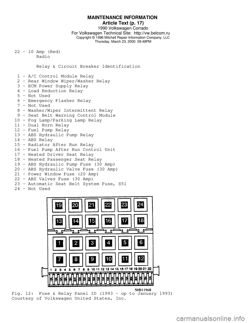
Relay & Circuit Breaker Identification
1 - A/C Control Module Relay
2 - Rear Window Wiper/Washer Relay
3 - ECM Power Supply Relay
4 - Load Reduction Relay
5 - Not Used
6 - Emergency Flasher Relay
7 - Not Used
8 - Washer/Wiper Intermittent Relay
9 - Seat Belt Warning Control Module
10 - Fog Lamp/Parking Lamp Relay
11 - Dual Horn Relay
12 - Fuel Pump Relay
13 - ABS Hydraulic Pump Relay
14 - ABS Relay
15 - Radiator After Run Relay
16 - Fuel Pump After Run Control Unit
17 - Heated Driver Seat Relay
18 - Heated Passenger Seat Relay
19 - ABS Hydraulic Pump Fuse (30 Amp)
20 - ABS Hydraulic Valve Fuse (30 Amp)
21 - Power Window Fuse (20 Amp)
22 - ABS Valves Fuse (30 Amp)
23 - Automatic Seat Belt System Fuse, S51
24 - Not UsedFig. 12: Fuse & Relay Panel ID (1993 - up to January 1993)
Courtesy of Volkswagen United States, Inc.
Page 654 of 906
MAINTENANCE INFORMATION
Article Text (p. 19)
1990 Volkswagen Corrado
For Volkswagen Technical Site: http://vw.belcom.ru
Copyright © 1998 Mitchell Repair Information Company, LLC
Thursday, March 23, 2000 09:48PM
Radio
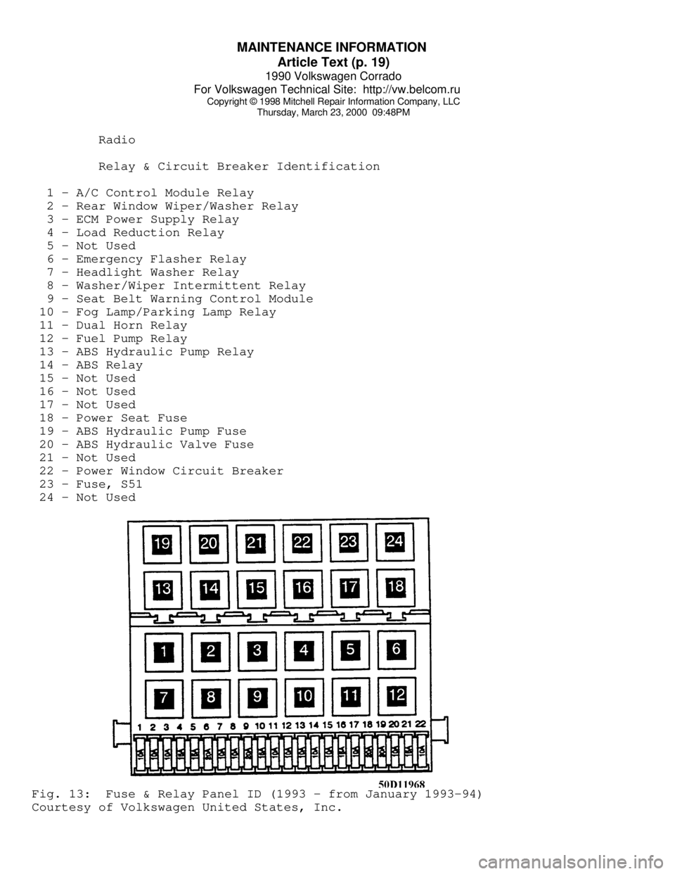
Relay & Circuit Breaker Identification
1 - A/C Control Module Relay
2 - Rear Window Wiper/Washer Relay
3 - ECM Power Supply Relay
4 - Load Reduction Relay
5 - Not Used
6 - Emergency Flasher Relay
7 - Headlight Washer Relay
8 - Washer/Wiper Intermittent Relay
9 - Seat Belt Warning Control Module
10 - Fog Lamp/Parking Lamp Relay
11 - Dual Horn Relay
12 - Fuel Pump Relay
13 - ABS Hydraulic Pump Relay
14 - ABS Relay
15 - Not Used
16 - Not Used
17 - Not Used
18 - Power Seat Fuse
19 - ABS Hydraulic Pump Fuse
20 - ABS Hydraulic Valve Fuse
21 - Not Used
22 - Power Window Circuit Breaker
23 - Fuse, S51
24 - Not UsedFig. 13: Fuse & Relay Panel ID (1993 - from January 1993-94)
Courtesy of Volkswagen United States, Inc.