Page 1097 of 2103
AUTOMATIC TRANSAXLE
ENGINE (TURBO) AND ENGINE>
12. Temporarily install valve body
pin in the valve, groove.
oil sensor arid holder and tighten bolts
with the specified torque.,
A bolt: 18 mm long
bolt: 25 mm in.) long
bolt: 40 mm (1.57 long
body assembly mounting ,
1 1 N m ( 8 . 0
13. Install oil filter.
14. Install a new oil pan gasket and pan.
15. Pour in the specified amount of ATF.
16.. Perform the oil pressure test. Readjust if nec essary.
TSB Revision
Page 1098 of 2103

AUTOMATIC TRANSAXLE
ENGINE (TURBO) AND ENGINE> On-vehicle
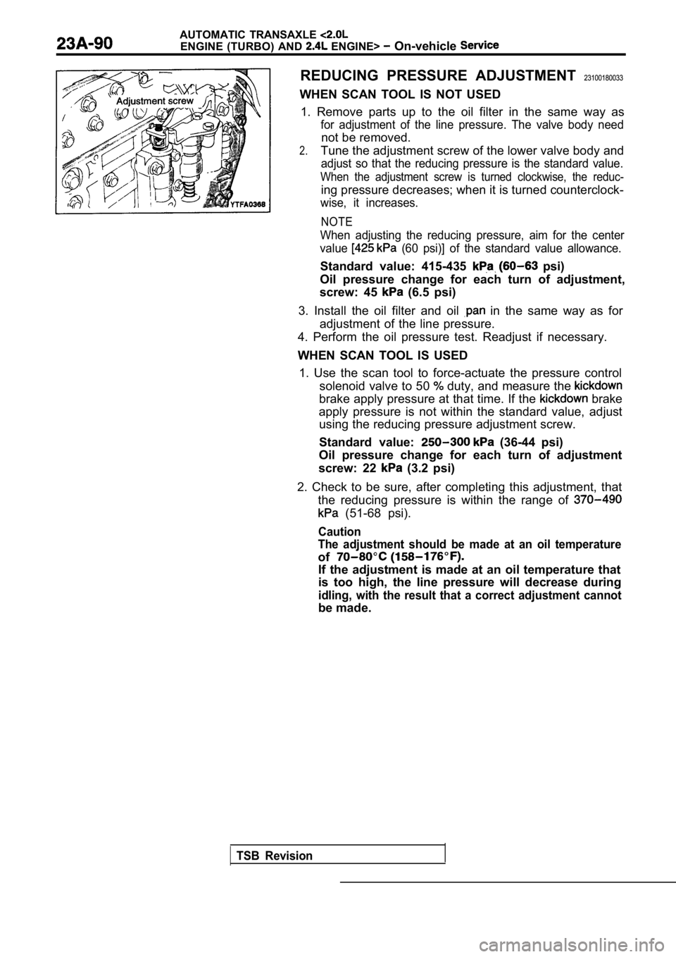
REDUCING PRESSURE ADJUSTMENT 23100180033
WHEN SCAN TOOL IS NOT USED 1. Remove parts up to the oil filter in the same wa y as
for adjustment of the line pressure. The valve body need
not be removed.
2.Tune the adjustment screw of the lower valve body a nd
adjust so that the reducing pressure is the standard value.
When the adjustment screw is turned clockwise, the reduc-
ing pressure decreases; when it is turned counterclock-
wise, it increases.
NOTE
When adjusting the reducing pressure, aim for the c enter
value
(60 psi)] of the standard value allowance.
Standard value: 415-435 psi)
Oil pressure change for each turn of adjustment,
screw: 45
(6.5 psi)
3. Install the oil filter and oil
in the same way as for
adjustment of the line pressure.
4. Perform the oil pressure test. Readjust if neces sary.
WHEN SCAN TOOL IS USED 1. Use the scan tool to force-actuate the pressure control
solenoid valve to 50
duty, and measure the
brake apply pressure at that time. If the brake
apply pressure is not within the standard value, ad just
using the reducing pressure adjustment screw.
Standard value:
(36-44 psi)
Oil pressure change for each turn of adjustment
screw: 22
(3.2 psi)
2. Check to be sure, after completing this adjustme nt, that
the reducing pressure is within the range of
(51-68 psi).
Caution
The adjustment should be made at an oil temperature
of
If the adjustment is made at an oil temperature tha t
is too high, the line pressure will decrease during
idling, with the result that a correct adjustment c annot
be made.
TSB Revision
Page 1149 of 2103

AUTOMATIC TRANSAXLE
ENGINE (NON-TURBO)> Troubleshooting
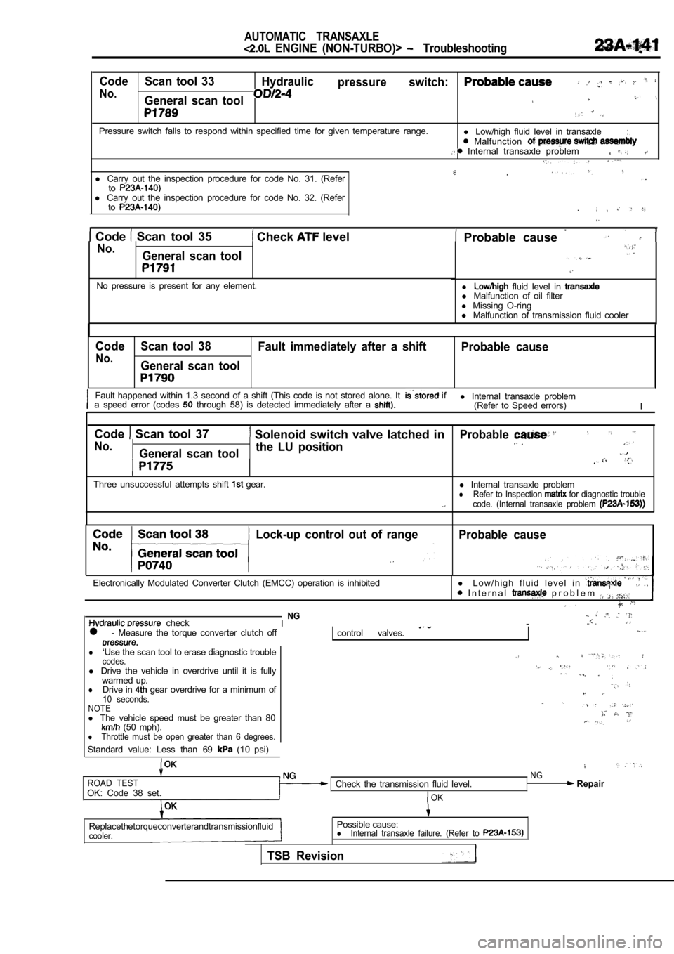
Code Scan tool 33Hydraulicpressureswitch:
No.General scan tool
Pressure switch falls to respond within specified t ime for given temperature range.
l Low/high fluid level in transaxle Malfunction Internal transaxle problem
,l Carry out the inspection procedure for code No. 31. (Refertol Carry out the inspection procedure for code No. 32. (Refer
to
Code Scan tool 35 Check level . Probable cause No.General scan tool
No pressure is present for any element.l fluid level in l
Malfunction of oil filter
l Missing O-ring
l Malfunction of transmission fluid cooler
Code Scan tool 38
Fault immediately after a shift Probable cause
No.General scan tool
Fault happened within 1.3 second of a shift (This code is not stored alone. It if
a speed error (codes through 58) is detected immediately after a l Internal transaxle problem
(Refer to Speed errors) I
Code
Scan tool 37 Solenoid switch valve latched in
No.General scan tool the LU position
Three unsuccessful attempts shift gear.
Probable
l
Internal transaxle problemlRefer to Inspection for diagnostic trouble
code. (Internal transaxle problem
Lock-up control out of rangeProbable cause
Electronically Modulated Converter Clutch (EMCC) op eration is inhibitedl L o w / h i g h f l u i d l e v e l i n I n t e r n a l p r o b l e m
checkNGI -..< .
l - Measure the torque converter clutch offcontrol valves.
l‘Use the scan tool to erase diagnostic troublecodes.l Drive the vehicle in overdrive until it is fully
warmed up.
lDrive in gear overdrive for a minimum of10 seconds.NOTEl The vehicle speed must be greater than 80 (50 mph).lThrottle must be open greater than 6 degrees.
Standard value: Less than 69 (10 psi)
ROAD TESTOK: Code 38 set. Check the transmission fluid level.OK
NG Repair
Replacethetorqueconverterandtransmissionfluid
cooler.
Possible cause:lInternal transaxle failure. (Refer to
TSB Revision
Page 1164 of 2103
AUTOMATIC TRANSAXLE
ENGINE (NON-TURBO)> Troubleshooting
Trouble symptom
torque converter control shift
PROBABLE CAUSE
No.Probable cause
18Drive shaft(s) bushing(s) worn or damaged
19Worn or broken reaction shaft support sealing
20Worn or damaged input shaft sealing
21Valve body malfunction or leakage
22Hydraulic pressure too low
23Hydraulic pressure too high
24 Faulty oil pump
25Oil filter clogged
26Low fluid level
27 High fluid level
28Aerated fluid
29 Engine idle too low
30Engine idle too high
31Normal solenoid operation
32Solenoid sound cover loose
33Sticking lockup piston
34 Torque converter failure
TSB Revision
Page 1210 of 2103
A U T O M A T I C T R A N S A X L E
OVERHAUL General Information
6
II II
1.Torque converter
2.Front clutch
3.Rear clutch
4.Low-reverse brake
5.End clutch
6. servo
7. Transaxle control module
8. Torque converter clutch control valve 9. Torque converter clutch solenoid 10. Rear clutch exhaust valve
11. shift valve
12.Reducing valve13. Shift control solenoid valve
14. shift valve 15. End clutch valve
16. Torque converter control valve 17. Shift control solenoid valve
18. Shift control valve
19. N-D control valve
20.Regulator valve
21.Manual valve
22. Pressure control valve23.Oil pump24.Oil filter
25.Oil pan
26. Line relief valve 27. N-R control valve
28. Pressure control solenoid valve
Page 1215 of 2103
AUTOMATIC
TORQUE SPECIFICATIONS
Items
Bearing retainer bolts2015
Converter housing bolts16
Detent plate mounting bolt1 1
Differential drive gear bolts135
Drain3324.
End clutch cover bolts
End cover bolts
Idler shaft lock plate bolt
servo lock nut
7
5
54
2921
Manual control lever nut19
Manual control shaft set screw97
Oil filter bolts
Oil pan bolts
Oil pump assembly mounting bolts
One-way clutch outer race lock plate bolts
Park/neutral position switch bolts
Pressure check plug
Pulse generator bolts
Pump housing to reaction shaft support bolts1 18--
21
16
40 ,
8
9 7
8 ,
118 .
Solenoid valve mounting bolts5
Speedometer sleeve locking plate bolt3
Sprag rod support bolts
Transfer shaft lock nut2 4
215
Valve body assembly mounting bolts
Valve body bolts11
.5
TSB
Page 1223 of 2103
A U T O M A T I C T R A N S A X L EOVERHAUL Transaxle
the snap ring and remove
switch.
(8) Remove the oil pan and oil gasket.
(9) Remove the oil filter.
the oil temperature sensor bracket. mounting
bolts’and remove the oil temperature sensor from brack-
et. Using a screwdriver, push out the rubber plug,
from inside the case, and remove the oil temperatur e
sensor from the case..
(11) With their catches pressed down, force the har
ness grom-
met and connector into the transaxle case:,
TSB Revision
Page 1279 of 2103
VALVE BODY
A U T O M A T I C T R A N S A X L E
OVERHAUL
DISASSEMBLY AND REASSEMBLY
Viewed A
. .
16
Lubricate all internal with automatic
fluid
during reassembly.
5
Disassembly steps
1. Manual valve 2. Pressure control solenoid valve 3. Shift control solenoid valve “A” 4. Shift control converter clutch
Valve stopper
8. N-D control sleeve
9. N-D control valve
10. Lower valve body sub assembly
11. Lower separating plate
12. Nut
Jet Relief spring
15. ball 16. Oil filter. 17. Upper valve body sub assembly 18. Steel ball 19. Teflon 20. N/D plate21.
22. Upper plate23. Dowel bushing24. Intermediate plate
TSB Revision