Page 108 of 2103

ENGINE OVERHAUL
Items Standard value
Piston ring end gap mm (in.)
Piston pin O.D. mm (in.)
0 . 8
Oil 9 . 8
21
Piston pin press-in load (Ibs.)
[Room temperature]
Crankshaft pin oil clearance mm (in.) 17,500
Connecting rod big end side clearance mm (in.)
Crankshaft, flywheel and drive plate
Bearing cap bolt shank length mm (in.)
0 . 4
Crankshaft end play mm (in.)
Crankshaft journal O.D. mm (in.) 0 . 2 5
57 (2.24)
pin O.D. mm (in.) 42 (1.77)
Crankshaft journal oil clearance mm (in.)
to cylinder clearance mm (in.)
0 . 1
block flatness of gasket surface mm (in.) 0.05 0.1
block grinding limit of gasket surface mm (in.)l 0.2‘Total resurfacing depth of both cylinder head and cylinder block
block overall height mm (in.)283.9-284.1
(11.177-11.185)
block I.D. mm (in.) 85.0 (3.35)
TSBRevision
REWORK DIMENSIONS
Items
Cylinder head and valve
Oversize rework dimensions of valve guide0.05 O.S.
hole (both intake and exhaust) mm (in.) 0.25 O.S.
0.50
Intake oversize rework 0.3
dimensions of valve seat hole mm (in.)
0.6 O.S.
Exhaust oversize rework dimensions of valve 0.3 O.S.
seat hole
mm (in.)0.6 O.S.
Crankshaft, flywheel and drive plate
Crankshaft out of roundness and taper of journal an d pin mm (in.)
Standard value
12.25-12.27 ,
,
Max. 0.01
NOTE
O.D.: Outer diameter
I.D.: Inner diameter
Oversize diameter
Page 111 of 2103
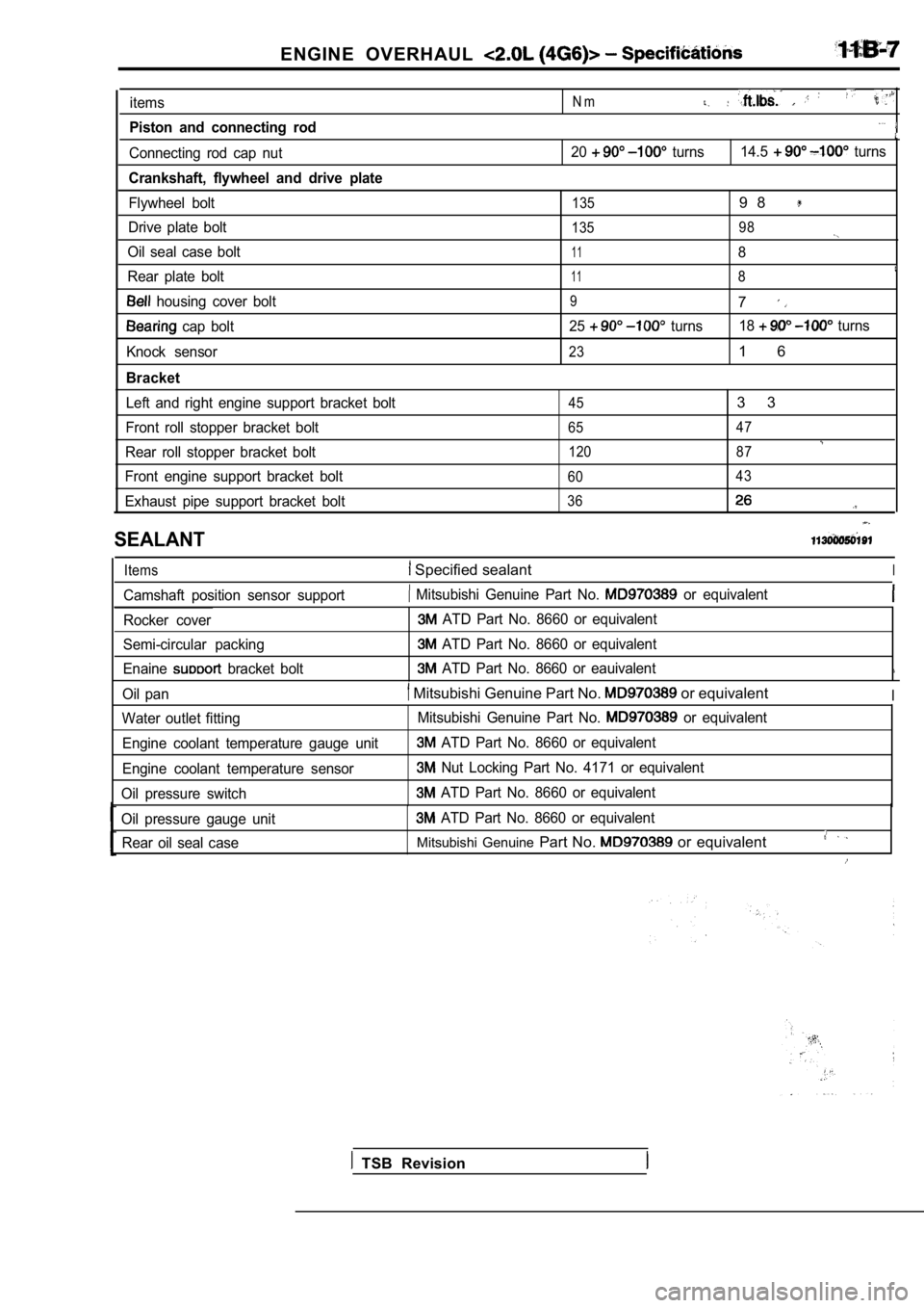
ENGINE OVERHAUL
items
Piston and connecting rod
Connecting rod cap nut
Crankshaft, flywheel and drive plate
Flywheel bolt
Drive plate bolt
Oil seal case bolt
Rear plate bolt
housing cover bolt
cap bolt
Knock sensor
Bracket
Left and right engine support bracket bolt
Front roll stopper bracket bolt
Rear roll stopper bracket bolt
Front engine support bracket bolt
Exhaust pipe support bracket bolt
N m
20 turns 14.5 turns
1359 8
135 98
118
118
97
25 turns18 turns
231 6
453 3
65 47
120 87
60 43
36
SEALANT
Items Specified sealantI
Camshaft position sensor support Mitsubishi Genuine Part No. or equivalent
Rocker cover
Semi-circular packing
Enaine
bracket bolt
ATD Part No. 8660 or equivalent
ATD Part No. 8660 or equivalent
ATD Part No. 8660 or eauivalent
Oil pan Mitsubishi Genuine Part No. or equivalentI
Water outlet fitting
Engine coolant temperature gauge unit
Engine coolant temperature sensor
Oil pressure switch Mitsubishi Genuine Part No. or equivalent
ATD Part No. 8660 or equivalent
Nut Locking Part No. 4171 or equivalent
ATD Part No. 8660 or equivalent
Oil pressure gauge unit
ATD Part No. 8660 or equivalent
Rear oil seal case
Mitsubishi Genuine Part No. or equivalent
TSB Revision
Page 119 of 2103
OVERHAUL Timing
BELT “B” REMOVAL
(1) Make a mark on the back of the timing belt indi cating
the direction of rotation so it may be reassembled in the’
same direction if it is to be reused.
NOTE
(1) Water or oil on the belt shortens its life drastically,
so the removed timing belt, sprocket, and tensioner
must be free from oil and water. These should
not be washed. Replace parts if seriously
(2) If there is oil or water on each part, check fr ont case
oil seals, camshaft oil seal and water pump for
COUNTERBALANCE SHAFT SPROCKET
REMOVAL
SPROCKET “B” REMOVAL
CAMSHAFT’ SPROCKET BOLT LOOSENING
(1)Using a wrench, hold the camshaft at its hexagon (b etween
the No. 2 and No. 3 journals) and remove the camshaft
sprocket bolt.
Caution
Locking the camshaft sprocket with a tool damages
the sprocket.
(2) Remove the camshaft sprockets.
,
TSB Revision
Page 120 of 2103
ENGINE OVERHAUL Timing Belt,
INSTALLATION SERVICE POINTS
CAMSHAFT SPROCKETS TIGHTENING
(1)Using a wrench, hold the camshaft at its hexagon (between
the No. 2 and No. 3 journals) and tighten the bolt to
the specification.
Caution
Locking the camshaft sprocket with a tool damages
the sprocket.
ENGINE SUPPORT BRACKET INSTALLATION
(1) Coat the bolts illustrated with
Specified sealant:
ATD Part No. 8660 or equivalent
SEALANT APPLICATION ON
PACKING
Specified sealant:
ATD Part No.
Page 123 of 2103
ENGINE OVERHAUL Belt
Phillips screwdriver
BOLT
O I L S P R O C K E T
(1) a Phillips screwdriver [shank diameter 8 mm
in.) shaft] through the plug hole on the the
cylinder block to block the left counterbalance sha ft.
(2)
the oil pump sprocket. .
(3) Apply a proper amount of engine oil-to the bearing
of the nuts.
(4) Tighten the nuts to the specified‘ torque.
AUTO TENSIONER INSTALLATION
(1) If the auto tensioner rod is in its fully exten ded position,
reset it as follows.
(2) Clamp the auto-tensioner in the vise
jaws.
(3) Push in the rod little by little with the vise the
hole A in the rod is aligned with the hole in the
(4) a wire mm in.) diameter] into the
(5) Unclamp the auto tensioner from the vise.
.
,
the auto tensioner to front case and tighten.
the specified torque.
Caution
Leave the wire installed the
,
. .
,
TSB Revision
Page 124 of 2103
ENGINE OVERHAUL
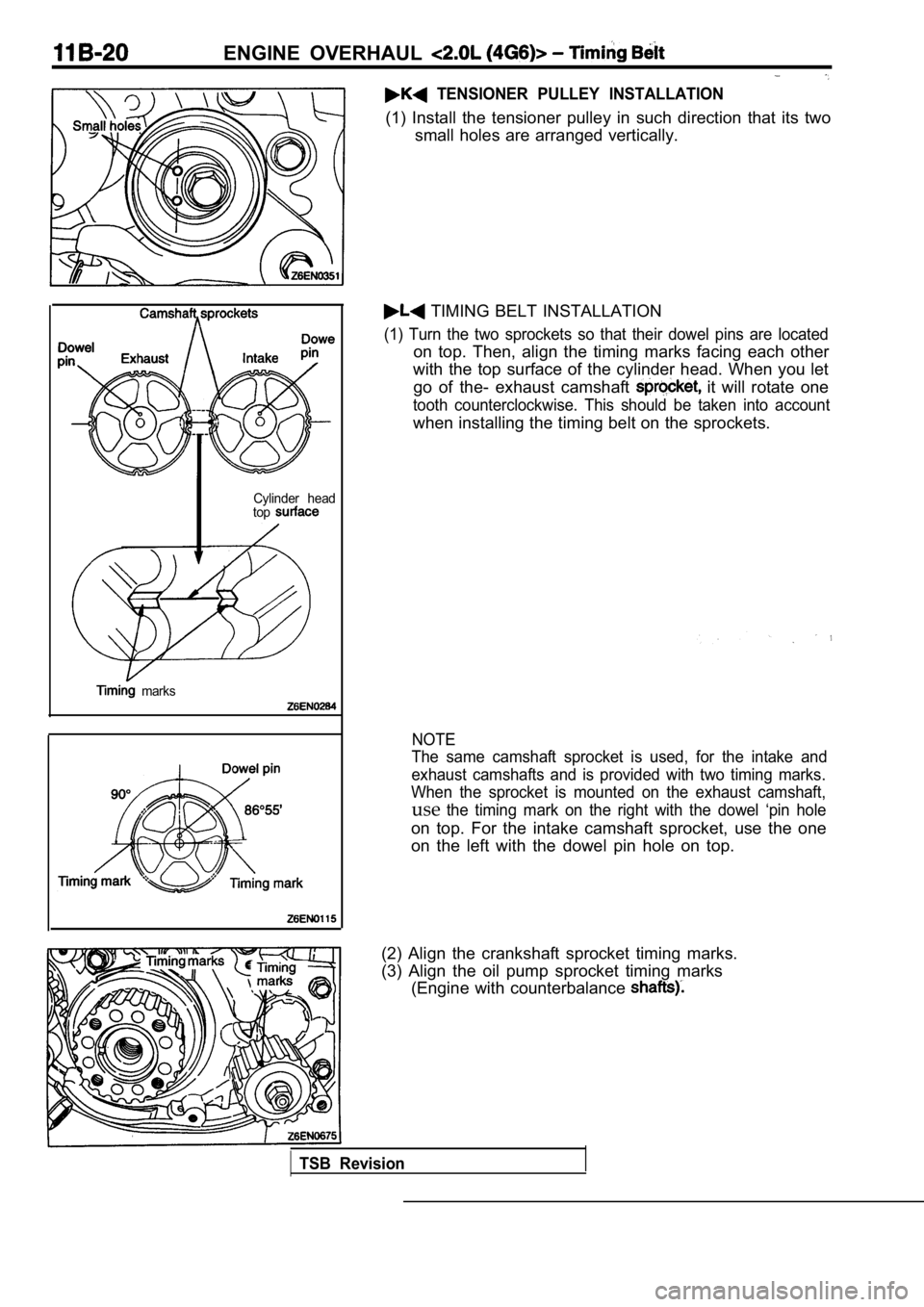
TENSIONER PULLEY INSTALLATION
(1) Install the tensioner pulley in such direction that its two
small holes are arranged vertically.
Cylinder head
top
marks
TIMING BELT INSTALLATION
(1) Turn the two sprockets so that their dowel pins are located
on top. Then, align the timing marks facing each ot her
with the top surface of the cylinder head. When you let
go of the- exhaust camshaft
it will rotate one
tooth counterclockwise. This should be taken into a ccount
when installing the timing belt on the sprockets.
NOTE
The same camshaft sprocket is used, for the intake and
exhaust camshafts and is provided with two timing m arks.
When the sprocket is mounted on the exhaust camshaf t,
usethe timing mark on the right with the dowel ‘pin hole
on top. For the intake camshaft sprocket, use the o ne
on the left with the dowel pin hole on top.
(2) Align the crankshaft sprocket timing marks.
(3) Align the oil pump sprocket timing marks (Engine with counterbalance
TSB Revision
Page 126 of 2103
ENGINE OVERHAUL Timing
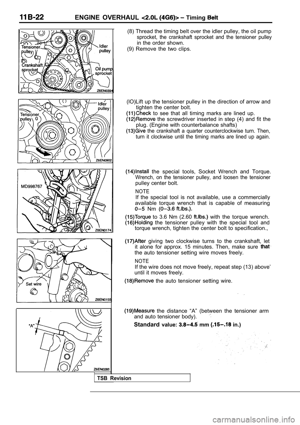
(8) Thread the timing belt over the idler pulley, the oil pump
sprocket, the crankshaft sprocket and the tensioner pulley
in the order shown.
(9) Remove the two clips.
(lO)Lift up the tensioner pulley in the direction o f arrow and
tighten the center bolt.
to see that all timing marks are lined up.
the screwdriver inserted in step (4) and fit the
plug. (Engine with counterbalance shafts)
the crankshaft a quarter counterclockwise turn. Th en,
turn it clockwise until the timing marks are lined up again.
the special tools, Socket Wrench and Torque.
Wrench, on the tensioner pulley, and loosen the ten sioner
pulley center bolt.
NOTE
If the special tool is not available, use a commercially
available torque wrench that is capable of measurin g
Nm
to 3.6 Nm (2.60 with the torque wrench.
the tensioner pulley with the special tool and
torque wrench, tighten the center bolt to specifica tion.,
giving two clockwise turns to the crankshaft, let
it alone for approx. 15 minutes. Then, make sure
the auto tensioner setting wire moves freely.
NOTE
If the wire does not move freely, repeat step (13) above’
until it moves freely.
the auto tensioner setting wire.
the distance “A” (between the tensioner arm
and auto tensioner body).
Standard value: mm in.)
TSB Revision
Page 132 of 2103
11ENGINE OVERHAUL
in.)diameterbead
diameter
bead sealant
SEALANT APPLICATION TO THERMOSTAT
HOUSING
Specified sealant:
Mitsubishi Genuine Part No. or equiva-
lent
NOTE
(1) Be sure to install the housing quickly while th e
sealant is wet (within 15 minutes).
(2) After installation, keep the sealed area away f rom
the oil and coolant for hour.
SEALANT APPLICATION TO WATER OUTLET
Specified sealant:
Mitsubishi Genuine Part No. or equiva-
lent
NOTE
(1) Be sure to install the housing quickly while the
is wet (within 15 minutes).
(2) After installation, keep the sealed area away f rom
the oil and coolant for approx. 1 hour.
SEALANT APPLICATION TO ENGINE COOLANT
TEMPERATURE SENSOR
Specified sealant:
Nut Locking ‘Part No. 4171 or equivalent
SEALANT APPLICATION TO ENGINE COOLANT
TEMPERATURE GAUGE UNIT
Specified sealant: ATD Part No. 8660 or equivalent
TSB Revision


