Page 140 of 2103
11E N G I N E O V E R H A U L
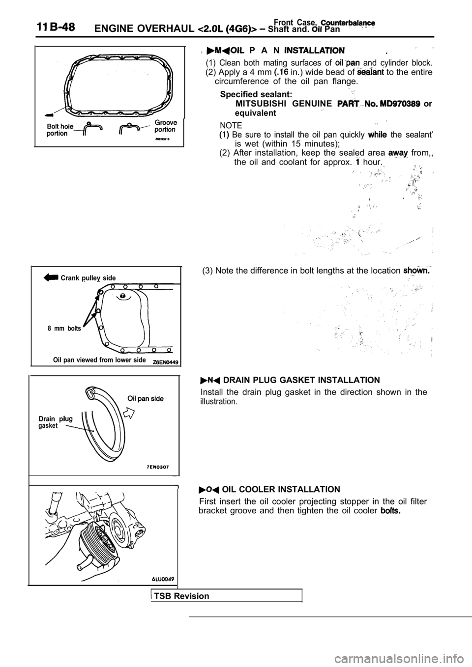
CYLINDER HEAD AND VALVES11300690201
REMOVAL AND INSTALLATION
Removal steps1. Cylinder head bolt
head assembly
Retainer lock
5. Valve spring retainer
6. Valve spring
7. Intake valve 8. Retainer lock
9. Valve spring retainer
10. Valve spring
TSB Revision
11.Exhaust valve
12. Valve stem seal 13. Valve spring seat
14. Valve stem seal
15. Valve spring seat
16. Intake valve guide
17. Exhaust valve guide
18. Intake valve seat
19. Exhaust valve seat
20.Cylinderhead
Page 142 of 2103
11 E N G I N E O V E R H A U L Cylinder Head
Identification mark
RETAINER LOCK . .
The ‘valve spring,if excessively, compressed, causes the
bottom end of retainer to be in contact with, and d amage,:
the stem seal.
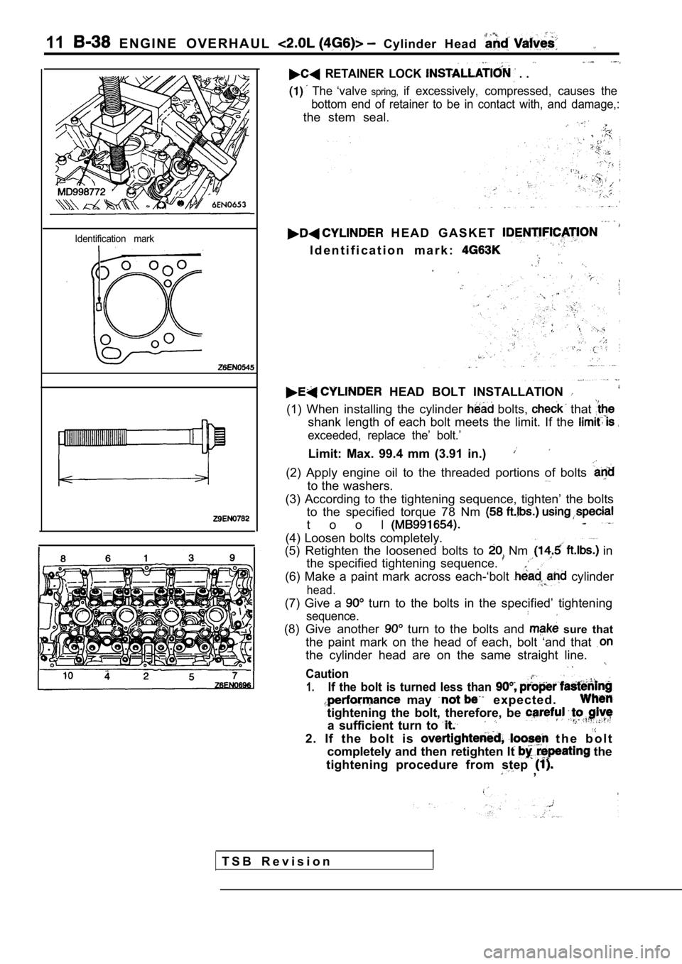
H E A D G A S K E T
I d e n t i f i c a t i o n m a r k :
HEAD BOLT INSTALLATION
(1) When installing the cylinder bolts, that
shank length of each bolt meets the limit. If the
exceeded, replace the’ bolt.’
Limit: Max. 99.4 mm (3.91 in.)
(2) Apply engine oil to the threaded portions of bo lts
to the washers.
(3) According to the tightening sequence, tighten’ the bolts
to the specified torque 78 Nm
t o o l
(4) Loosen bolts completely.
(5) Retighten the loosened bolts to
Nm in
the specified tightening sequence.
(6) Make a paint mark across each-‘bolt cylinder
head.
(7) Give a turn to the bolts in the specified’ tightening
sequence.
(8) Give another turn to the bolts and sure that
the paint mark on the head of each, bolt ‘and that
the cylinder head are on the same straight line.
Caution
1.If the bolt is turned less than
may e x p e c t e d .
tightening the bolt, therefore, be
a sufficient turn to
2. If the bolt is t h e b o l t
completely and then retighten It
the
tightening procedure from step
,
T S B R e v i s i o n
Page 147 of 2103
Front Case,
ENGINE OVERHAUL and Pan
Phillips screwdriver
F r o n tbearing
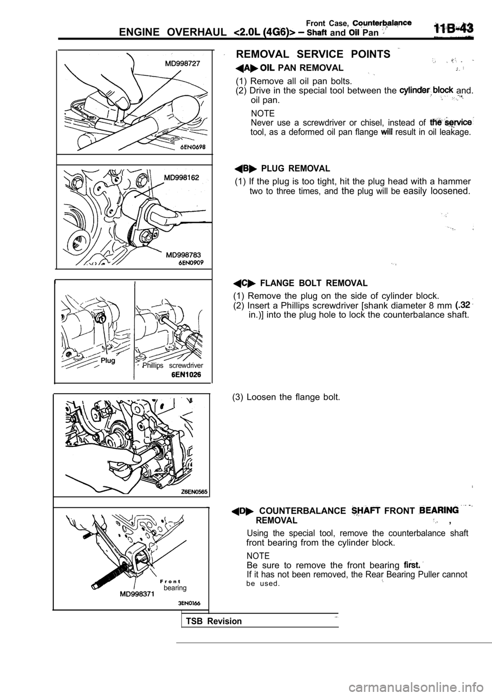
REMOVAL SERVICE POINTS
PAN REMOVAL
(1) Remove all oil pan bolts.
(2) Drive in the special tool between the
and.
oil pan.
NOTE
Never use a screwdriver or chisel, instead of
tool, as a deformed oil pan flange result in oil leakage.
PLUG REMOVAL
(1) If the plug is too tight, hit the plug head wit h a hammer
two to three times, and theplug will be easily loosened.
FLANGE BOLT REMOVAL
(1) Remove the plug on the side of cylinder block.
(2) Insert a Phillips screwdriver [shank diameter 8 mm
in.)] into the plug hole to lock the counterbalance shaft.
(3) Loosen the flange bolt.
COUNTERBALANCE FRONT
REMOVAL ,
Using the special tool, remove the counterbalance s haft
front bearing from the cylinder block.
NOTE
Be sure to remove the front bearing
If it has not been removed, the Rear Bearing Puller cannot
b e u s e d .
TSB Revision
Page 148 of 2103
11Front Case, ENGINE OVERHAUL Shaft and
Rear bearing
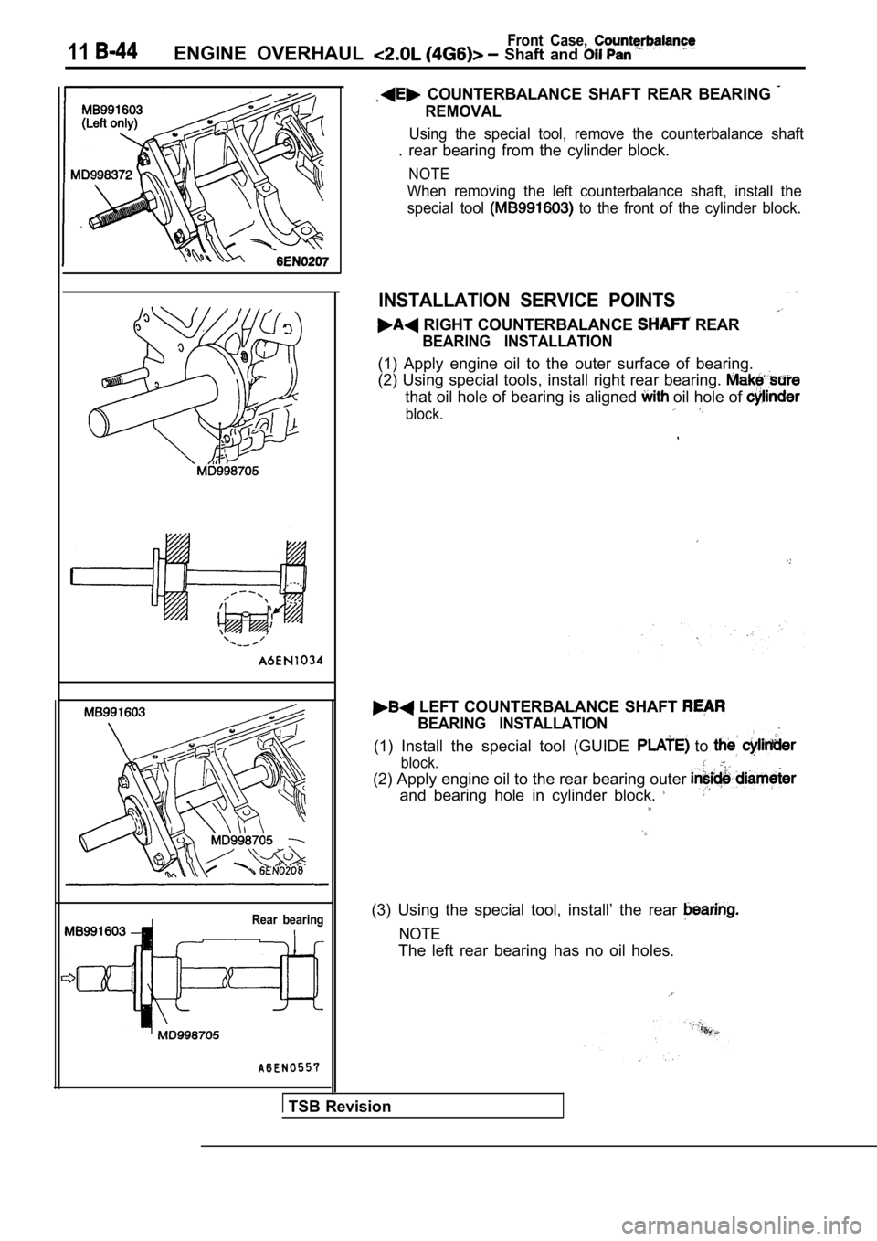
COUNTERBALANCE SHAFT REAR BEARING
REMOVAL
Using the special tool, remove the counterbalance shaft
. rear bearing from the cylinder block.
NOTE
When removing the left counterbalance shaft, install the
special tool
to the front of the cylinder block.
INSTALLATION SERVICE POINTS
RIGHT COUNTERBALANCE REAR
BEARING INSTALLATION
(1) Apply engine oil to the outer surface of bearin g.
(2) Using special tools, install right rear bearing .
that oil hole of bearing is aligned oil hole of
block.
,
LEFT COUNTERBALANCE SHAFT
BEARING INSTALLATION
(1) Install the special tool (GUIDE to
block.
(2) Apply engine oil to the rear bearing outer
and bearing hole in cylinder block.
(3) Using the special tool, install’ the rear
NOTE
The left rear bearing has no oil holes.
TSB Revision
Page 149 of 2103
Front Case, Counterbalance
ENGINE OVERHAUL Shaft and
C y l i n d e rblock
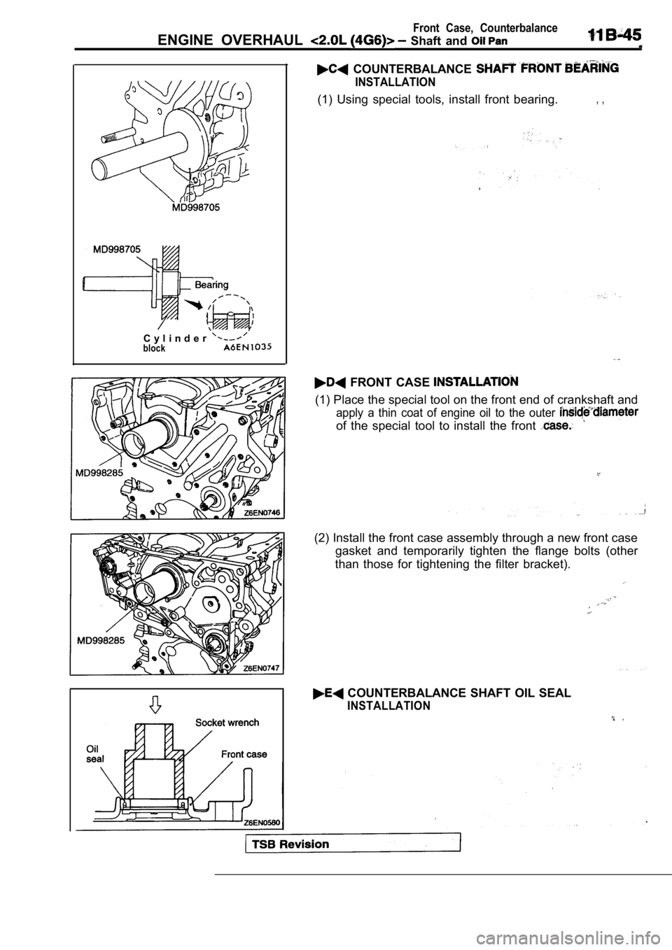
COUNTERBALANCE
INSTALLATION
(1) Using special tools, install front bearing., ,
FRONT CASE
(1) Place the special tool on the front end of crankshaft and
apply a thin coat of engine oil to the outer
of the special tool to install the front
(2) Install the front case assembly through a new f ront case
gasket and temporarily tighten the flange bolts (ot her
than those for tightening the filter bracket).
COUNTERBALANCE SHAFT OIL SEAL
INSTALLATION
Page 151 of 2103
Front Case,, ENGINE OVERHAUL Shaft and ‘Pan
Phillips screwdriver
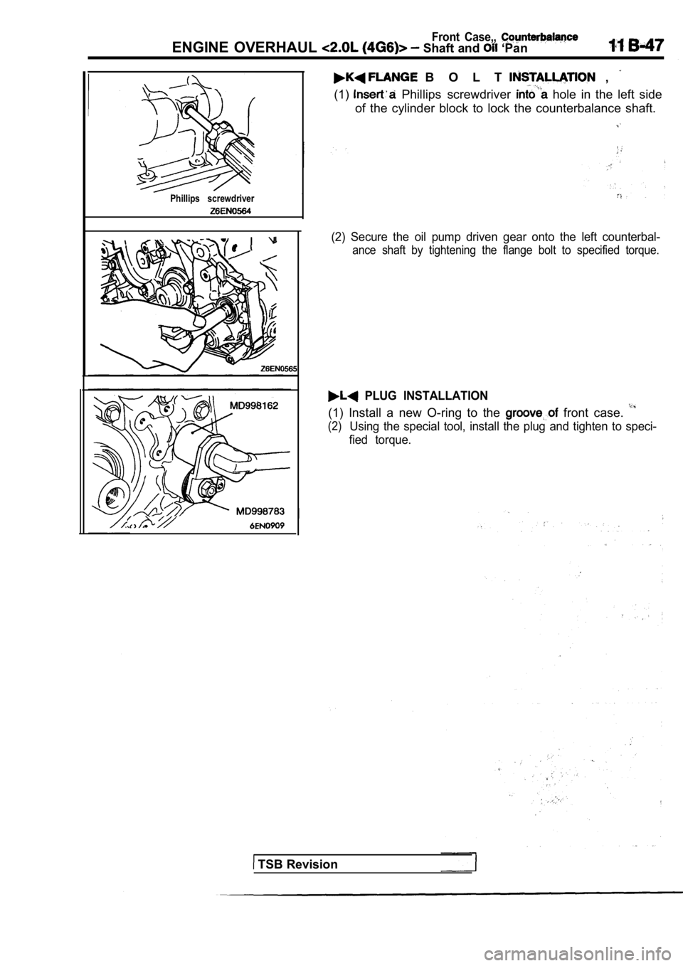
B O L T ,
(1) Phillips screwdriver hole in the left side
of the cylinder block to lock the counterbalance sh aft.
(2) Secure the oil pump driven gear onto the left c ounterbal-
ance shaft by tightening the flange bolt to specified torque.
PLUG INSTALLATION
(1) Install a new O-ring to the front case.
(2)Using the special tool, install the plug and tighten to speci-
fied torque.
TSB Revision
Page 152 of 2103
Front Case, ENGINE OVERHAUL Shaft and. Pan
Crank pulley side
8 mm bolts
Oil pan viewed from lower side
Drain pigasket
P A N .
(1) Clean both mating surfaces of and cylinder block.
(2) Apply a 4 mm in.) wide bead of to the entire
circumference of the oil pan flange.
Specified sealant:
MITSUBISHI GENUINE or
equivalent
NOTE. .
Be sure to install the oil pan quickly the sealant’
is wet (within 15 minutes);
(2) After installation, keep the sealed area
from,,
the oil and coolant for approx.
hour.
, .
(3) Note the difference in bolt lengths at the loca
tion
DRAIN PLUG GASKET INSTALLATION
Install the drain plug gasket in the direction show n in the
illustration.
OIL COOLER INSTALLATION
First insert the oil cooler projecting stopper in t he oil filter
bracket groove and then tighten the oil cooler
TSB Revision
Page 156 of 2103

11 ENGINE OVERHAUL Piston and Rod
Piston pin settingtool 6941
11
Presspin
Piston pinFront mark
Connecting rod
guide pin
R E M O V A L S E R V I C E
ROD CAP
(1) Mark the cylinder number on the side of connecting
rod big end for correct reassembly.
(2) Keep the removed connecting rods, caps, ‘andbearings
in order according to the cylinder number.
PISTON PIN REMOVAL
No.Part No.
1
2 0136
3 0137
4 0138
5
Description
Base
Piston Support
Connecting Rod Guide Pin
Connecting Rod Guide Pin
Connecting Rod Guide Pin
6 0140 Piston SupportI
7
8 0142
Connecting Rod Guide Pin
Piston Support
9 Press PinI
10 216943 Stop Screw
11 10396 NutI
(1) Remove the stop screw from the base.
(2) Select the correct piston support for your appl ication (See
above). Fit the piston support onto the base. Place the
base on press support blocks.
TSB Revision
(3) Insert the press pin through the piston pin hol e. Select
the correct connecting rod guide pin (See above). T hread
the guide pin onto the threaded portion of the press pin.
(4) Position the piston assembly on the piston supp ort in
the press. With the press pin up as shown in Figure 4,
insert the guide pin through the hole in the piston and
through the hole in the piston support.
(5) Press the piston pin out of the assembly.
IMPORTANT: To avoid piston damage,
l The piston support must seat squarely against
the piston.
lVerify that the piston pin will slide through the
hole in the piston support.
(6) Remove the piston pin from the press pin.