1990 MITSUBISHI SPYDER door lock
[x] Cancel search: door lockPage 1899 of 2103

B O D Y Entry System
When all doors are locked with the transmitter, the theft-alarm system is not set. (The SECURITY
indicator doesn’t illuminate, and the alarm doesn’t function.)
When all doors are locked with the key, is the theft-alarm systemCheck the theft-alarm to GROUP 54 set?
System.)
Yes ,
Check the following connectors: and NG Repair
OK
Check trouble symptom.
NG NG
Disconnect the receiver connector measure harnessCheck the harness wire between the receiver and ETA CS-ECU.side.l Voltage between the terminal (15) and ground
OK: (Pulse output)’
OK
Replace the receiver.1
NOTEl : Using an oscilloscope
When the PANIC switch of the transmitter is pressed , the headlights do not flash and the horns
do not sound. (However, the theft-alarm functions n ormally.)
with theft-alarm system>
[Comment]When the PANIC switch is pressed, the receiver sends a PANIC signal to ETACS-ECU. Then the ECU flashes the headlights and sounds
the horns intermittently for approx. three minutes.
The headlights and horns share an operation circuit with the theft-alarm system. Because of this, if the theft-alarm system functions normally,
the
harness between the receiver and the ETACS-ECU mav be defective.
N GCheck the operation of the theft-alarm system. (Refer to GROUP Carry out troubleshooting for the theft-alarm 54 Theft-alarm System.) 1’
Repair
OK
Check trouble 1
NG
harness
side.
l Voltage between the terminal (15) and ground
OK: (Pulse output)
OK
the receiver.
N GCheck the harness wire between the receiver and ETA CS-ECU.
NOTEl : Using an oscilloscope
TSB Revision
Page 1900 of 2103
42-76B O D Y Entry System
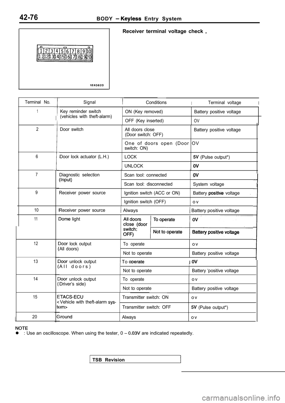
Terminal No.
1
2
6
7
9
10
11
12
13
14
15
20
Receiver terminal voltage check ,
SignalConditionsITerminal voltageI
Key reminder switch
(vehicles with theft-alarm) ON (Key removed)
OFF (Key inserted) Battery positive voltage
OV
Door switch
Door lock actuator (L.H.) All doors close
(Door switch: OFF) Battery positive voltage
O n e o f d o o r s o p e n ( D o o r O V
switch: ON)
LOCK
(Pulse output*)
UNLOCK
Diagnostic selection
Receiver power source Scan tool: connected
Scan tool: disconnected Ignition switch (ACC or ON)
Ignition switch (OFF)
System voltage
Battery
voltage
o v
,
TSB Revision
Receiver power source Always Battery positive voltage
light
lock output
All doors)To operate
Not to operate
o v
Battery positive voltage
unlock output
A l l d o o r s ) To
Not to operate
II
Battery ‘positive voltage
unlock output
Driver’s side)To operate
Not to operate
o v
Battery positive voltage
Transmitter switch: ONo vVehicle with theft-alarm
Transmitter switch: OFF (Pulse output*)
Alwayso v
l : Use an oscilloscope. When using the tester, 0
are indicated repeatedly.
I
Page 1901 of 2103
B O D Y Entry System
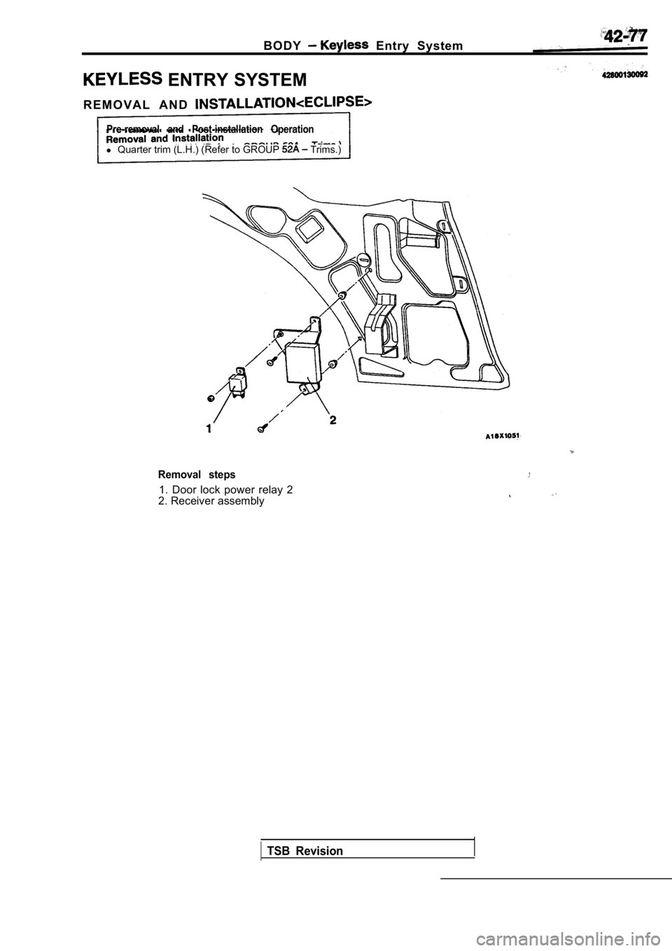
ENTRY SYSTEM
R E M O V A L A N D
Pre-removal and Post-installation Operation
l Quarter trim (L.H.) (Refer to GROUP Trims.)
Removal steps
1. Door lock power relay 2
2. Receiver assembly
TSB Revision
Page 1902 of 2103
B O D Y Entry System
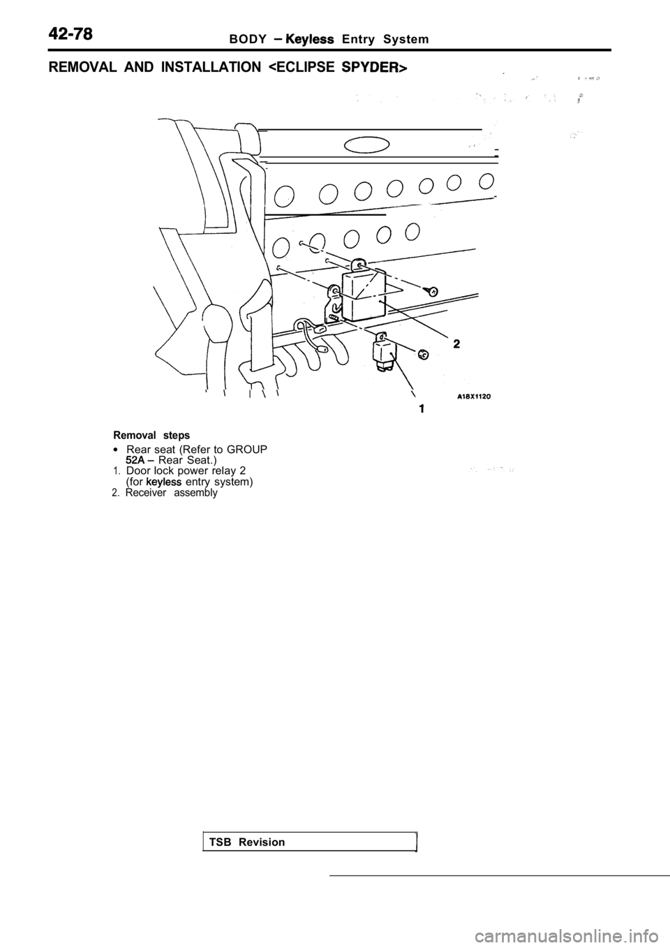
REMOVAL AND INSTALLATION
Removal steps
l
1.
2.
Rear seat (Refer to GROUP Rear Seat.)
Door lock power relay 2
(for
entry system)Receiver assembly
TSB Revision
Page 1903 of 2103

BODY Entry System
Battery
INSPECTION
DOOR LOCK POWER RELAY 2 CHECK
Refer to
REPLACEMENT
(1) insert a screwdriver in a slit in the transmitt er
pry it lightly to open the case. Then take the batt ery out
of the transmitter.
(2) Install a new battery with its positive side do wn.
Replacement battery: Coin typebattery
2
(3) Firmly close the transmitter case.
(4) Check that the
entry system operates properly.
Caution
When the transmitter is opened, be not to
allow water, dust, etc. to
to the
In addition, do not touch the precision electronic
device.
TSB Revision
Page 1904 of 2103
Entry System
METHOD OF REGISTERING A SECRET CODE
Each individual secret code is registered inside the transmitter,
and so it is necessary to register these codes with the received
in the following cases.
lWhen either the transmitter or receiver is replaced;
lIf a second transmitter is to be used;
lIf it appears that a problem is occurring because o f faulty
registration of a code.
A maximum of two different codes per transmitter ca n be
stored in the memory area of the EEPROM, and up to two
different transmitters can be used. When the codes for the
first transmitter are registered, the previously-registered codes
for both transmitters are cleared. Therefore, if yo u are using
two transmitters or are adding a second transmitter , the
for both transmitters must be the same time.
(1) Check that the door locking function works norm ally using
the door key.
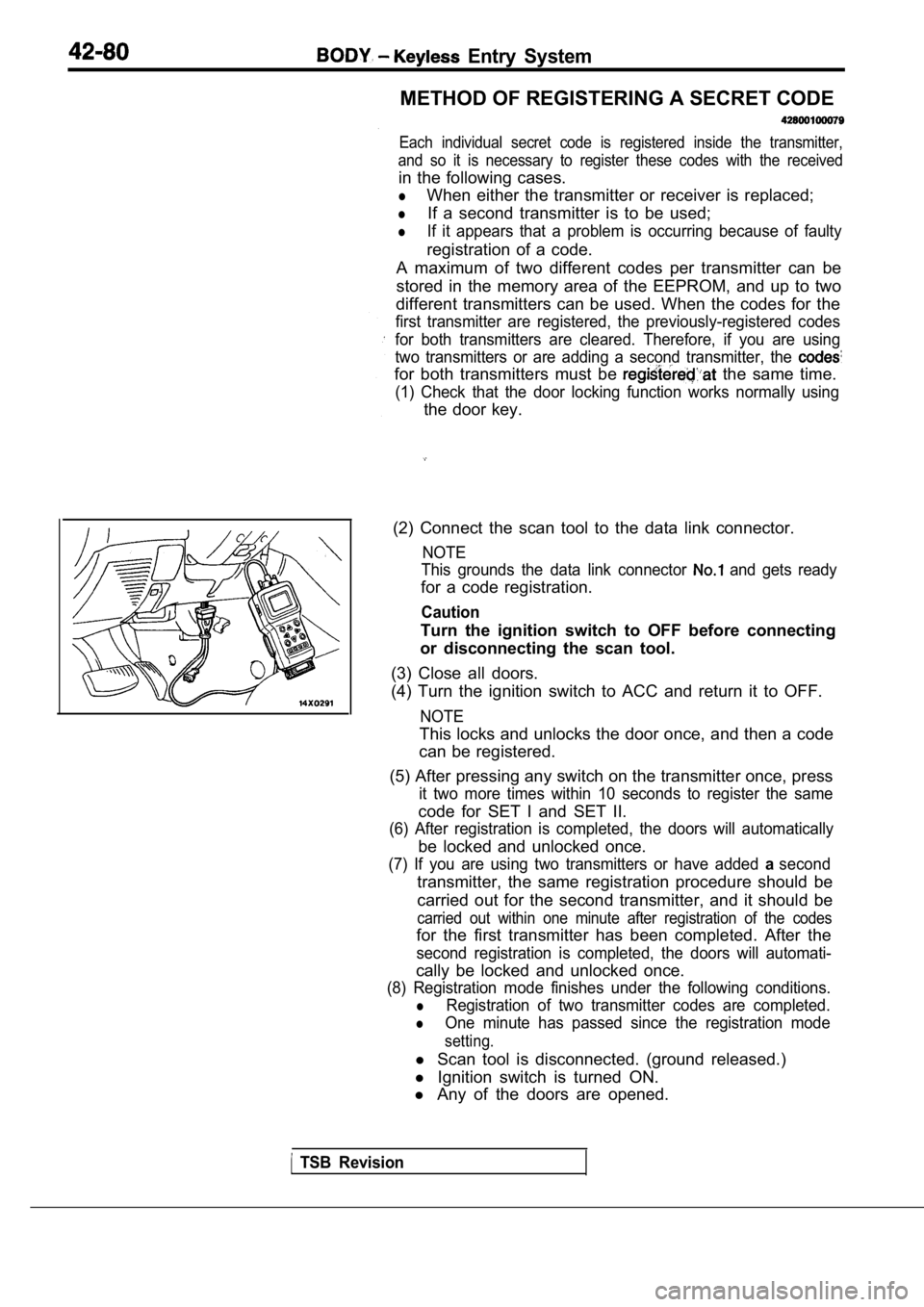
(2) Connect the scan tool to the data link connecto r.
NOTE
This grounds the data link connector
and gets ready
for a code registration.
Caution
Turn the ignition switch to OFF before connecting
or disconnecting the scan tool.
(3) Close all doors.
(4) Turn the ignition switch to ACC and return it t o OFF.
NOTE
This locks and unlocks the door once, and then a co de
can be registered.
(5) After pressing any switch on the transmitter on ce, press
it two more times within 10 seconds to register the same
code for SET I and SET II.
(6) After registration is completed, the doors will automatically
be locked and unlocked once.
(7) If you are using two transmitters or have added asecond
transmitter, the same registration procedure should be
carried out for the second transmitter, and it shou ld be
carried out within one minute after registration of the codes
for the first transmitter has been completed. After the
second registration is completed, the doors will au tomati-
cally be locked and unlocked once.
(8) Registration mode finishes under the following conditions.
lRegistration of two transmitter codes are completed .
lOne minute has passed since the registration mode
setting.
l Scan tool is disconnected. (ground released.)
l Ignition switch is turned ON.
l Any of the doors are opened.
TSB Revision
Page 2001 of 2103
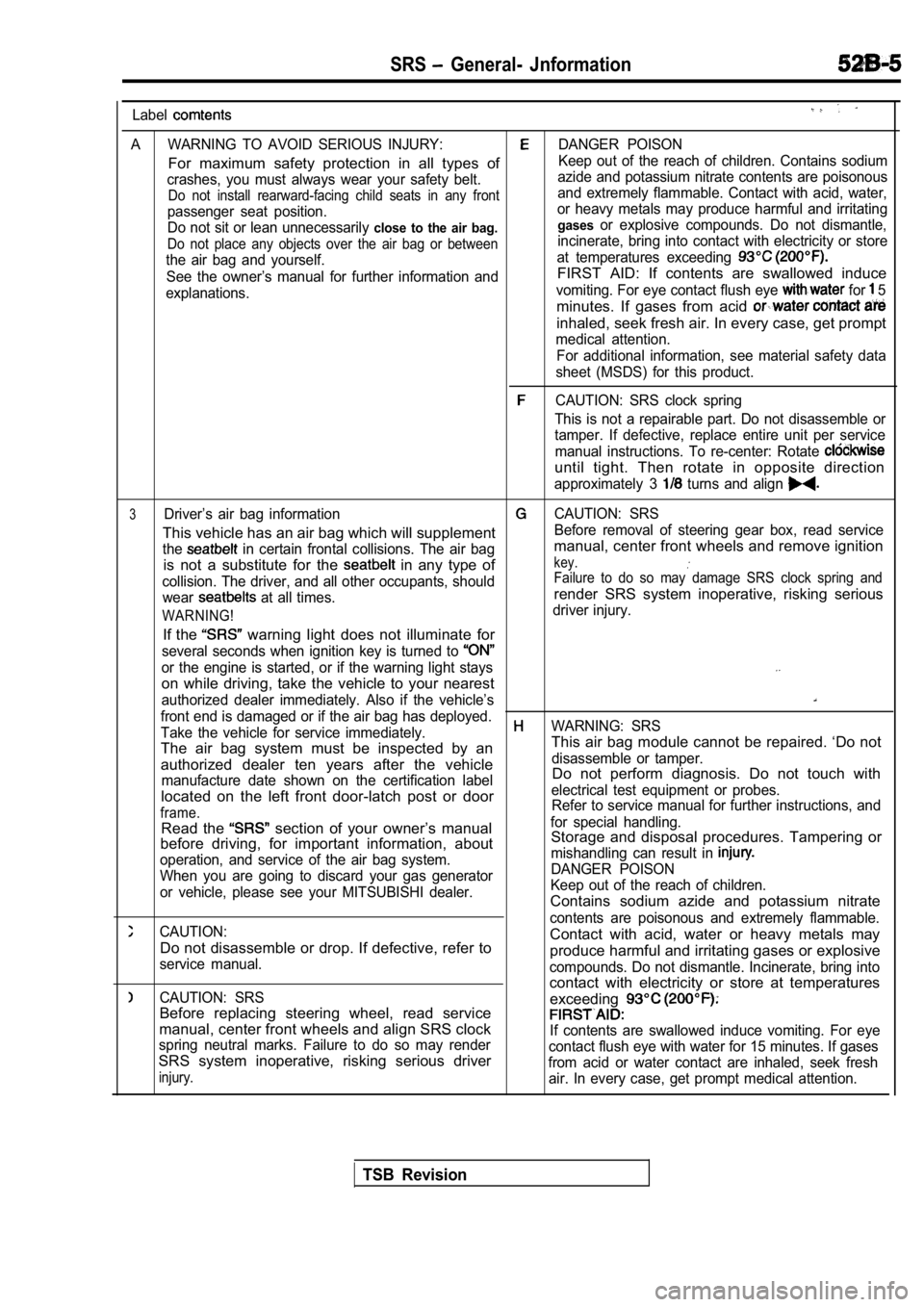
SRS General- Jnformation
Label
A WARNING TO AVOID SERIOUS INJURY:DANGER POISON
For maximum safety protection in all types ofKeep out of the reach of children. Contains sodium
crashes, you must always wear your safety belt. azide and potassium nitrate contents are poisonous
Do not install rearward-facing child seats in any f
rontand extremely flammable. Contact with acid, water,
passenger seat position. or heavy metals may produce harmful and irritating
Do not sit or lean unnecessarily
close to the air bag. gasesor explosive compounds. Do not dismantle,
Do not place any objects over the air bag or betwee
nincinerate, bring into contact with electricity or store
the air bag and yourself. at temperatures exceeding
See the owner’s manual for further information andFIRST AID: If contents are swallowed induce
explanations.vomiting. For eye contact flush eye for 5
minutes. If gases from acid
inhaled, seek fresh air. In every case, get prompt
medical attention.
For additional information, see material safety dat a
sheet (MSDS) for this product.
CAUTION: SRS clock spring
This is not a repairable part. Do not disassemble o r
tamper. If defective, replace entire unit per servi ce
manual instructions. To re-center: Rotate
until tight. Then rotate in opposite direction
approximately 3 turns and align
3Driver’s air bag informationCAUTION: SRS
This vehicle has an air bag which will supplementBefore removal of steering gear box, read service
the
in certain frontal collisions. The air bagmanual, center front wheels and remove ignition
is not a substitute for the
in any type ofkey.
collision. The driver, and all other occupants, sho uldFailure to do so may damage SRS clock spring and
wear at all times.render SRS system inoperative, risking serious
WARNING!driver injury.
If the warning light does not illuminate for
several seconds when ignition key is turned to
or the engine is started, or if the warning light stays
on while driving, take the vehicle to your nearest
authorized dealer immediately. Also if the vehicle’ s
front end is damaged or if the air bag has deployed .
Take the vehicle for service immediately.WARNING: SRS
The air bag system must be inspected by an This air bag module cannot be repaired. ‘Do not
authorized dealer ten years after the vehicledisassemble or tamper.
manufacture date shown on the certification labelDo not perform diagnosis. Do not touch with
located on the left front door-latch post or door
electrical test equipment or probes.
frame.Refer to service manual for further instructions, a nd
Read the section of your owner’s manualfor special handling.
before driving, for important information, about Storage and disposal procedures. Tampering or
operation, and service of the air bag system. mishandling can result in
When you are going to discard your gas generatorDANGER POISON
or vehicle, please see your MITSUBISHI dealer. Keep out of the reach of children.
Contains sodium azide and potassium nitrate
CAUTION:contents are poisonous and extremely flammable.
Do not disassemble or drop. If defective, refer toContact with acid, water or heavy metals may
service manual.produce harmful and irritating gases or explosive
compounds. Do not dismantle. Incinerate, bring into
CAUTION: SRScontact with electricity or store at temperatures
exceeding
Before replacing steering wheel, read service
manual, center front wheels and align SRS clockIf contents are swallowed induce vomiting. For eye
spring neutral marks. Failure to do so may render contact flush eye with water for 15 minutes. If gases
SRS system inoperative, risking serious driverfrom acid or water contact are inhaled, seek freshinjury.air. In every case, get prompt medical attention.
TSB Revision
Page 2036 of 2103
SRS Air Bag Module Disposal,. Procedures
AIR BAG MODULE DISPOSAL PROCEDURES 52499120999
Before either disposing of a vehicle equipped with
an air bag, or prior to disposing of the air bag ule, be sure to first follow the procedures describ ed
below to deploy the air bag.
A I R
Caution
1.If the vehicle is to be scrapped, or otherwise disp osed
of, deploy the air bag inside the vehicle. If the v ehicle
will continue to be operated and only the air bag m od-
ule is to be disposed of, deploy the air bag outside
the vehicle.
2. Since a large amount of smoke is produced when the air bag is deployed, select a well-ventilated s ite.
Moreover, never attempt the test near a smoke senso r.
3. Since there is a loud noise when the air bag is
deployed, avoid
areas whenever possible.
If anyone is nearby, give warning of the impending
noise.
4.Suitable ear protection be worn by personnel
performing these procedures or by people in the im-
mediate area.
DEPLOYMENT INSIDE THE VEHICLE
(when disposing of a vehicle)
(1) Open all windows and doors of. the vehicle. Mov e the
vehicle to an isolated spot.
(2)Disconnect the negative and positive battery cables
from the battery terminals, and then remove the bat tery
from the vehicle.
Caution
Wait at least 60 seconds after disconnecting the
tery cables before doing any further work.
(Refer to
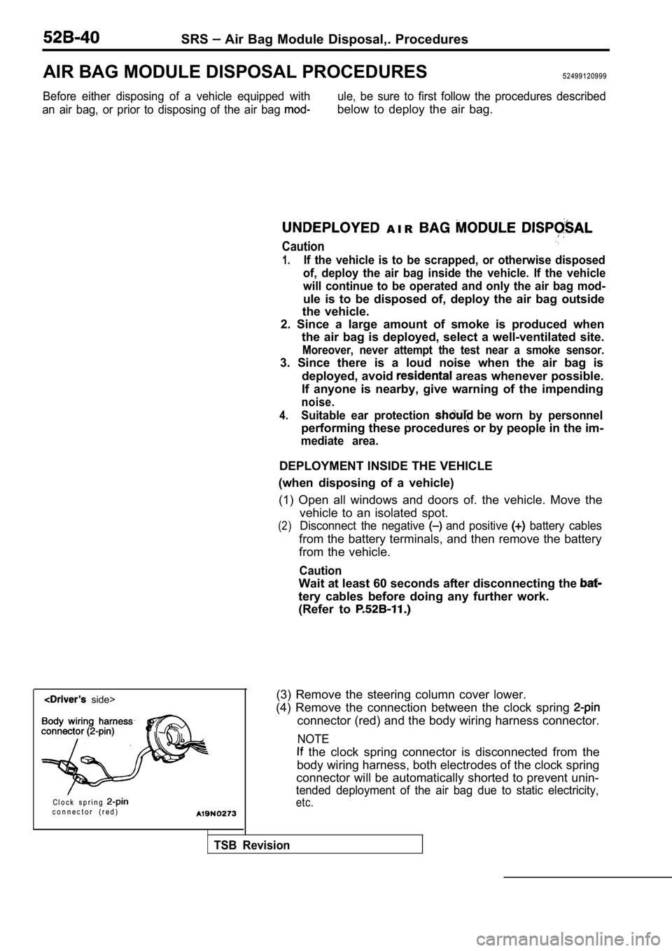
side>
C l o c k s p r i n g
c o n n e c t o r ( r e d )
(3) Remove the steering column cover lower.
(4) Remove the connection between the clock spring
connector (red) and the body wiring harness connect or.
NOTE
the clock spring connector is disconnected from th e
body wiring harness, both electrodes of the clock s pring
connector will be automatically shorted to prevent unin-
tended deployment of the air bag due to static elec tricity,
etc.
TSB Revision