Page 1863 of 2103
BODYDoor
When the power windows are not lowered fully, the
automatically if the convertible top switch is set to open or
.
Check trouble symptom.
NG.
Check the harness between the power window main swi tch and
the convertible top control module. Repair, if nece ssary.
,
When the power windows are not lowered fully and th e power window main
lock switch is OFF, the passenger’s side power wind ow does not lower automatically if
the convertible top switch is set to open or close. However, the passenger’s, side.
window lowers automatically when the lock switch ON;
N G Replace
OK .
Check the following connectors: a n d
N G
Repairw i n d o w i n a i n .
Revision
Page 1864 of 2103
BODY Door
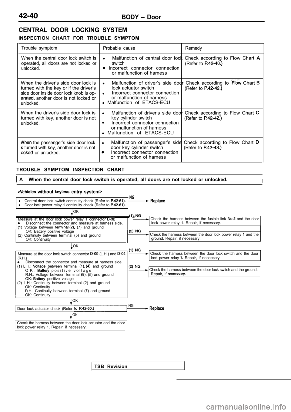
CENTRAL DOOR LOCKING SYSTEM
INSPECTION CHART FOR TROUBLE SYMPTOM
Trouble symptom Probable cause Remedy
When the central door lock switch is
l Malfunction of central door lock Check according to Flow Chart A
operated, all doors are not locked or switch
(Refer to
unlocked. Incorrect connector connection
or malfunction of harness
When the driver’s side door lock is lMalfunction of driver’s side door Check according t o
Chart
turned with the key or if the driver’slock actuator switch(Refer to side door inside door lock knob is op-lIncorrect connector connection
another door is not locked oror malfunction of harness
unlocked.l
Malfunction of ETACS-ECU
When the driver’s side door lock is l
Malfunction of driver’s side door Check according t o Flow Chart
turned with key, another door is notkey cylinder switch(Refer to
unlocked.l
Incorrect connector connection
or malfunction of harness
l Malfunction of ETACS-ECU
the passenger’s side door lockl Malfunction of passenger’s side Check according to
Flow Chart
turned with key, another door is notdoor key cylinder switch(Refer to
or unlocked.Incorrect connector connection
or malfunction of harness
TROUBLE SYMPTOM INSPECTION CHART
A When the central door lock switch is operated, al l doors are not locked or unlocked.I
without entry system>
NGlCentral door lock switch continuity check (Refer to ReplacelDoor lock power relay 1 continuity check (Refer to
TSB Revision
OK
Measure at the door lock power relay 1 connector Check the harness between the fusible link and the door
Disconnect the connector and measure at harness sid e.
Voltage between (7) and groundlock power relay 1. Repair, if necessary.
OK: Battery positive voltage
(2) Continuity between terminal (5) and ground OK: Continuity
OK
Measure at the door lock switch connector (L.H.) and (R.H.)Disconnect the connector and measure at harness sid e. L.H.: between terminal and groundO K : p o s i t i v e v o l t a g eR.H.: Voltage between terminal (5) and ground
OK: positive voltage
(2) L.H.: Continuity between terminal (2) and groun d
OK: Continuity
Continuity between terminal (7) and ground
OK: Continuity
OK
Door lock actuator check (Refer
OK
Check the harness between the door lock power rela y 1 and the
ground. Repair, if necessary.
Check the harness between the door lock switch and the door
lock power relay Repair, if necessary.
Check the harness between the door lock switch and the ground.
Repair, if
NG Replace
Check the harness between the door lock actuator an d the door
lock power relay 1. Repair, if necessary.
Page 1865 of 2103
BODY Door
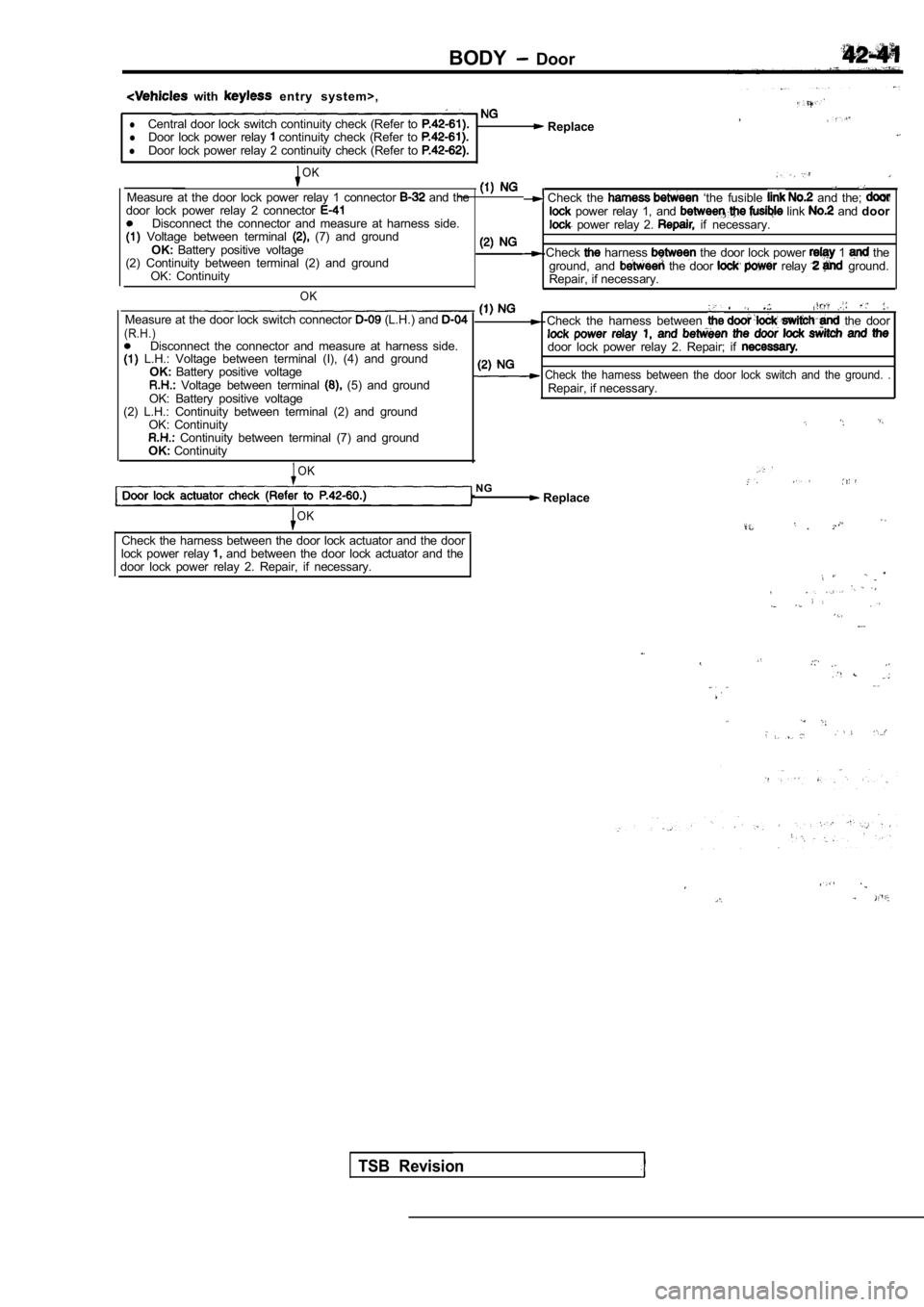
with e n t r y s y s t e m > ,
Central door lock switch continuity check (Refer to ,l ReplacelDoor lock power relay continuity check (Refer to lDoor lock power relay 2 continuity check (Refer to
OK
Measure at the door lock power relay 1 connector and the Check the ‘the fusible and the; door lock power relay 2 connector power relay 1, and link and door
Disconnect the connector and measure at harness sid e.
Voltage between terminal (7) and ground power relay 2. if necessary.
OK: Battery positive voltage
(2) Continuity between terminal (2) and ground
OK: Continuity
OK
Check harness the door lock power 1 the
ground, and the door relay ground.
Repair, if necessary.
Measure at the door lock switch connector (L.H.) and Check the harness between the door(R.H.)Disconnect the connector and measure at harness sid e. L.H.: Voltage between terminal (I), (4) and ground door lock power relay 2. Repair; if OK:
Battery positive voltage Check the harness between the door lock switch and the ground. . Voltage between terminal (5) and ground
Repair, if necessary.
OK: Battery positive voltage
(2) L.H.: Continuity between terminal (2) and groun d
OK: Continuity
Continuity between terminal (7) and ground
OK: Continuity
OK
NG Replace
OK
Check the harness between the door lock actuator an d the door
lock power relay and between the door lock actuator and the
door lock power relay 2. Repair, if necessary.
TSB Revision
Page 1866 of 2103
42-42BODY Door
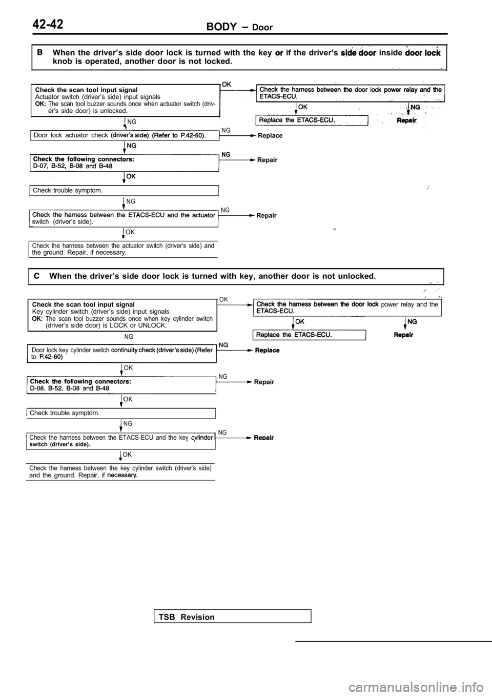
When the driver’s side door lock is turned with the key if the driver’s inside
knob is operated, another door is not locked.
.
Check the scan tool input signal
Actuator switch (driver’s side) input signals
OK:The scan tool buzzer sounds once when actuator swit ch (driv-er’s side door) is unlocked.
NG
Door lock actuator check N G Replace
NG
and Repair
Check trouble symptom.
NG NG
Repairswitch(driver’s side).
OK
Check the harness between the actuator switch (driv er’s side) andthe ground. Repair, if necessary.
When the driver’s side door lock is turned with key , another door is not unlocked.
OKCheck the scan tool input signalCheck the harness between the door power relay and the
Key cylinder switch (driver’s side) input signalsETACS-ECU.OK:The scan tool buzzer sounds once when key cylinder switch(driver’s side door) is LOCK or UNLOCK.
NG
Door lock key cylinder switch to
TSB Revision
OK
NG Repair and
Check trouble symptom.
OK
NG
Check the harness between the ETACS-ECU and the ke v NG
switch (driver’s side)., ,
OK
Check the harness between the key cylinder switch ( driver’s side)
and the ground. Repair, if
Page 1867 of 2103
BODY
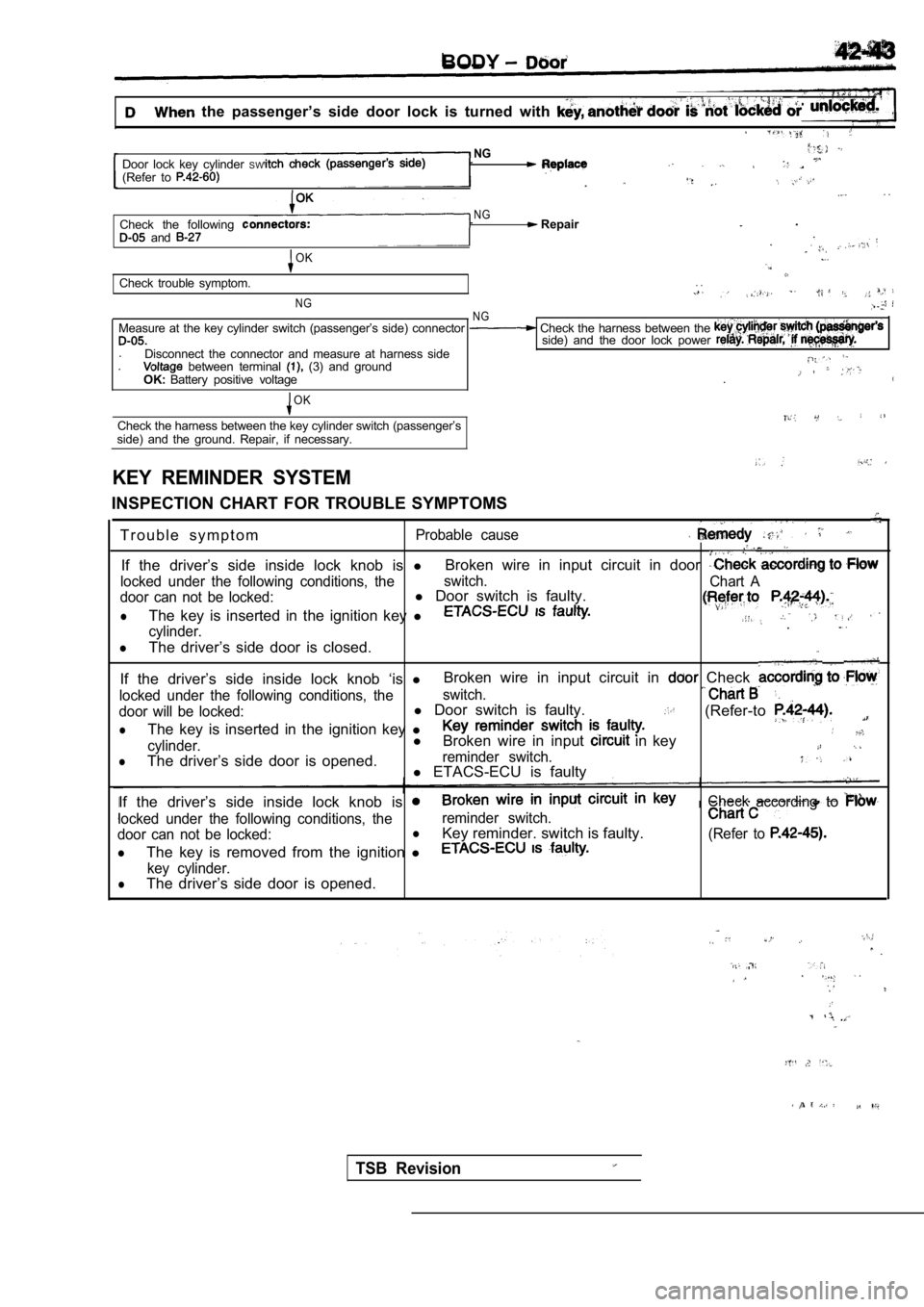
the passenger’s side door lock is turned with
NGDoor lock key cylinder SW(Refer to . .
NGCheck the following Repair.
and .
OK
Check trouble symptom.. .
NGN GMeasure at the key cylinder switch (passenger’s sid e) connector Check the harness between the side) and the door lock power .
Disconnect the connector and measure at harness sid e. between terminal (3) and groundOK:Battery positive voltage .
OK
Check the harness between the key cylinder switch (
passenger’s
side) and the ground. Repair, if necessary.
KEY REMINDER SYSTEM
INSPECTION CHART FOR TROUBLE SYMPTOMS
T r o u b l e s y m p t o m
Probable cause
If the driver’s side inside lock knob is lBroken wire in input circuit in door
locked under the following conditions, the switch.
Chart A
door can not be locked:l Door switch is faulty.
lThe key is inserted in the ignition key l
cylinder..
lThe driver’s side door is closed.
If the driver’s side inside lock knob ‘is lBroken wire in input circuit in Check
locked under the following conditions, the
switch.
door will be locked:l
Door switch is faulty.(Refer-to
lThe key is inserted in the ignition key l
cylinder.l
Broken wire in input in key
lThe driver’s side door is opened.reminder switch.l ETACS-ECU is faulty
If the driver’s side inside lock knob is
Check accordingto
locked under the following conditions, the reminder switch.
door can not be locked:lKey reminder. switch is faulty.(Refer to
lThe key is removed from the ignition l
key cylinder.lThe driver’s side door is opened.
TSB Revision
Page 1868 of 2103
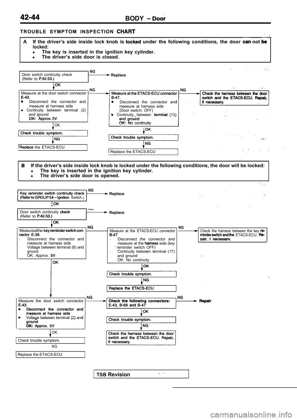
BODY
T R O U B L E S Y M P T O M I N S P E C T I O N
A If the driver’s side inside lock knob is under the following conditions, the door not
locked:
lThe key is inserted in the ignition key cylinder.
l The driver’s side door is closed.
Door switch continuity check
(Refer to
NG Replace
Measure at the door switch connector
Disconnect the connector and
measure at harness side
l Continuity between terminal (2)
and around
OK:
OK
the ETACS-ECU
NG
Disconnect the connector and
measure at harness side
(Door switch: OFF)
l Continuity between
(13)
OK: No continuity
Replace the ETACS-ECU
If the driver’s side inside lock knob is locked und er the following conditions, the door will be locke d:
l The key is inserted in the ignition key cylinder.
l The driver’s side door is opened.
NG Replace Switch.)
Door switch continuity (Refer to Replace
Measureatthe
.
Disconnect the connector and
measure at harness side
. Voltage between terminal (6) and
groundOK: Approx.
TSB Revision
Measure at the ETACS-ECU connector
.
Disconnect the connector and
measure at the side (key reminder switch OFF)
. Continuity between terminal (17)
and ground
OK: No continuity
NGCheck the harness between the key ETACS-ECU. if
Measure the door switch connector
Voltage between terminal (2) and
OK
Check trouble symptom.
NG
Replace the ETACS-ECU
Page 1869 of 2103
BODY Door
If the driver’s side inside lock knob is locked under the following conditions, the door can not
locked:lThe key is removed from the ignition key cylinder.
lThe driver’s side door is opened.
and
minder switch and the ETACS-ECU.
Replace the ETACS-ECU.
OK
NG Check the connectors:
between (4)
OK
Check trouble symptom.
N G
and
Replace the ETACS-ECU
TSB Revision
Page 1881 of 2103
B O D Y Door
Power window passenger’s
side switch Door lock
Power window
switch
driver’s sidePower window
s w i t c hlock switch
INSPECTION
POWER WINDOW MOTOR CHECK
(1) Check that the motor runs smoothly
the battery
is connected directly to the
terminals:
(2) Furthermore, check that the
operates in reverse
when the terminal connections
switched:
POWER WINDOW RELAY CONTINUITY CHECK
Battery voltage Terminal No.
Power is not supplied
Power is supplied
14
0 0
0
POWER WINDOW SWITCH CHECK
Main switch
TSB Revision