Page 1549 of 2103
R E A R
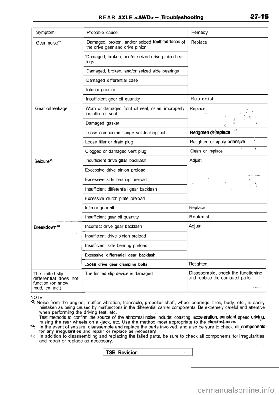
Symptom
Gear noise**
Gear oil leakage
The limited slip
differential does not
function (on snow, mud, ice, etc.)
NOTE
Noise from the engine, muffler vibration, transaxl e, propeller shaft, wheel bearings, tires, body, etc., is easily
mistaken as being caused by malfunctions in the dif ferential carrier components. Be extremely careful and attentive
when performing the driving test, etc.
Test methods to confirm the source of the abnormal include: coasting, speed
raising the rear wheels on a -jack, etc. Use the me thod most appropriate to the
In the event of seizure, disassemble and replace the parts involved, and also be sure to check for any irregularities and repair or replace as
l 4:In addition to disassembling and replacing the failed parts, be sure to check all components forirregularities
and repair or replace as necessary.
Probable cause Remedy
Damaged, broken, and/or seized
ofReplace
the drive gear and drive pinion
‘Damaged, broken, and/or seized drive pinion bear- ings
Damaged, broken, and/or seized side bearings
Damaged differential case
Inferior gear oil
Insufficient gear oil quantity
R e p l e n i s h
Worn or damaged front oil seal, OFan improperly Replace,
installed oil seal
Damaged gasket
Loose companion flange self-locking nut
Loose filler or drain plug Retighten or apply
‘Clean or replaceClogged or damaged vent plug
Insufficient drive
backlash
Excessive drive pinion preload
Excessive side bearing preload
Insufficient differential gear backlash
Excessive clutch plate preload
Inferior gear
oil
Insufficient gear oil quantity
Incorrect drive gear backlash
Insufficient drive pinion preload
Insufficient side bearing preload
Excessive differential gear backlash
drive gear clamping bolts
The limited slip device is damaged Adjust
Replace
Replenish
Adjust
Retighten
Disassemble, check the functioning
and replace the damaged parts
TSB Revision
Page 1599 of 2103
POWER PLANT MOUNT Crossmember
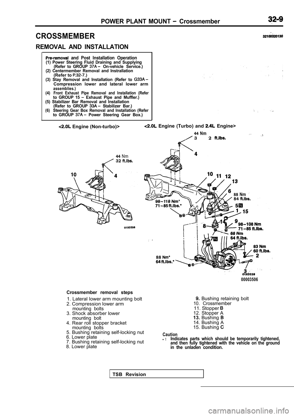
CROSSMEMBER
REMOVAL AND INSTALLATION
and Post Installation Operation(1) Power Steering Fluid Draining and Supplying(Refer to GROUP On-vehicle Service.)
(2) Centermember Removal and Instrallation
(Refer to (3) Stay Removal and Installation (Refer to Compression lower and lateral lower armassemblies.)(4)Front Exhaust Pipe Removal and Installation (Referto GROUP 15 Exhaust Pipe and Muffler.)
(5) Stabilizer Bar Removal and Installation (Refer to GROUP
Stabilizer Bar.)(6)Steering Gear Box Removal and Installation (Referto GROUP Power Steering Gear Box.)
Engine (Non-turbo)>
44Nm32
Engine (Turbo) and Engine>
44Nm3 2
88Nm84
88
00003506
Crossmember removal steps
1. Lateral lower arm mounting bolt
2. Compression lower arm
mounting bolts3. Shock absorber lowermounting bolt4. Rear roll stopper bracketmounting bolts5. Bushing retaining self-locking nut
6. Lower plate
7. Bushing retaining self-locking nut
8. Lower plate
Bushing retaining bolt10. Crossmember11. Stopper 12. Stopper A
13. Bushing
14. Bushing A
15. Bushing
Cautionl Indicates parts which should be temporarily tighten ed,
and then fully tightened with the vehicle on the gr ound
in the unladen condition.
TSB Revision
Page 1663 of 2103
BASIC BRAKE SYSTEM Master Cylinder and Brake Booster
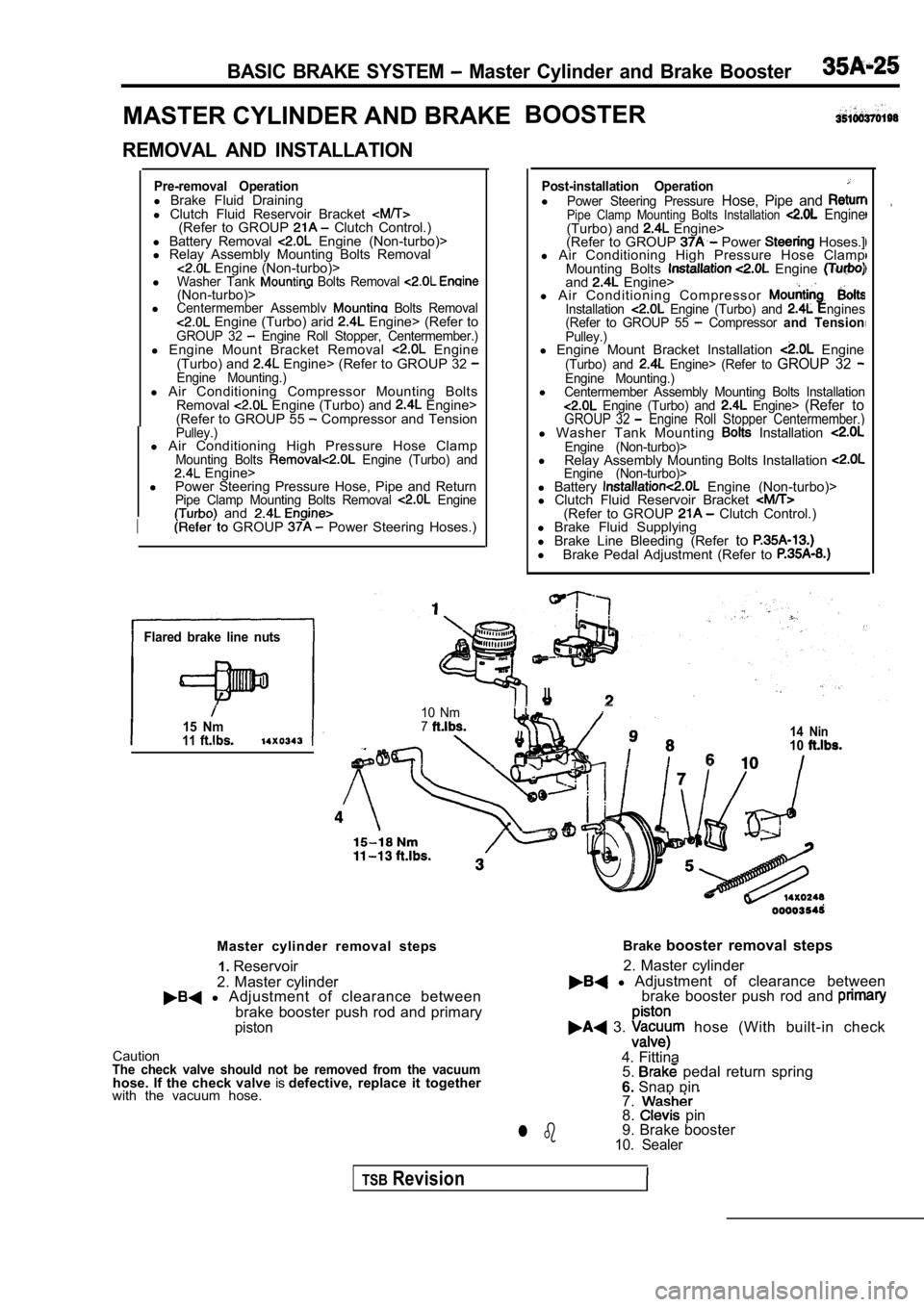
MASTER CYLINDER AND BRAKEBOOSTER
REMOVAL AND INSTALLATION
Pre-removal Operationl
Brake Fluid Draining
l Clutch Fluid Reservoir Bracket
(Refer to GROUP Clutch Control.)
l Battery Removal Engine (Non-turbo)>
l Relay Assembly Mounting Bolts Removal
Engine (Non-turbo)>
lWasher Tank Bolts Removal (Non-turbo)>lCentermember Assemblv Bolts Removal Engine (Turbo) arid Engine> (Refer toGROUP 32 Engine Roll Stopper, Centermember.)l Engine Mount Bracket Removal Engine
(Turbo) and Engine> (Refer to GROUP 32 Engine Mounting.)l Air Conditioning Compressor Mounting Bolts
Removal Engine (Turbo) and Engine>
(Refer to GROUP 55 Compressor and TensionPulley.)l Air Conditioning High Pressure Hose ClampMounting Bolts Engine (Turbo) and Engine>
l Power Steering Pressure Hose, Pipe and Return
Pipe Clamp Mounting Bolts Removal Engine and
I GROUP Power Steering Hoses.)
Flared brake line nuts
15 Nm11
Post-installation OperationlPower Steering Pressure Hose, Pipe and Pipe Clamp Mounting Bolts Installation Engine(Turbo) and Engine>
(Refer to GROUP Power Hoses.]
l Air Conditioning High Pressure Hose Clamp
Mounting Bolts
Engine and Engine>
l A i r C o n d i t i o n i n g C o m p r e s s o r
Installation Engine (Turbo) and ngines
(Refer to GROUP 55 Compressor and TensionPulley.)l Engine Mount Bracket Installation Engine(Turbo) and Engine> (Refer to GROUP 32 Engine Mounting.)lCentermember Assembly Mounting Bolts Installation Engine (Turbo) and Engine> (Refer toGROUP 32 Engine Roll Stopper Centermember.)l Washer Tank Mounting Installation Engine (Non-turbo)>l
Relay Assembly Mounting Bolts Installation Engine (Non-turbo)>l Battery Engine (Non-turbo)>
l Clutch Fluid Reservoir Bracket
(Refer to GROUP Clutch Control.)
l Brake Fluid Supplying
l Brake Line Bleeding (Refer to
l
Brake Pedal Adjustment (Refer to
I
10 Nm714 Nin10
Master cylinder removal steps
2. Master cylinder1.
Reservoir
l Adjustment of clearance between
brake booster push rod and primary
piston
CautionThe check valve should not be removed from the vacu umhose. If the check valve isdefective, replace it together
with the vacuum hose. Brake
booster removal steps
l Adjustment of clearance between
2. Master cylinder
brake booster push rod and
3. hose (With built-in check
4. Fittina 5.
pedal return spring
6. Snap pin
7.
8. pin
9. Brake booster
10. Sealerl b
TSBRevision
Page 1687 of 2103
P R O P O R T I O N I N G V A L V E,
REMOVAL AND INSTALLATION’.
O p e r a t i o n Operationl Brake Fluid DrainingLink Assembly Removal l Brakel l Engine (Turbo) and Engine>Brake Line fer l
Link Assembly Bolts Installation (Refer to GROUP Control.) Engine l Intake Manifold ( R e f e r ’ t o Engine (Non-turbo)> Intake Manifold (Refer to Manifold.) Engine ( R e f e r : G R O U P
Flared brake line nuts
11
TSB Revision
Removal steps
1. Brake pipe connection
2. Proportioning valve
0 0 0 0 0 0 7 4
Page 1722 of 2103
ABS
PROPORTIONING VALVE
REMOVAL AND
Operationl Brake Fluid Draining
l Link Assembly Mounting Bolts Removal
Engine (Turbo) and Engine> (Refer to GROUP17 Auto-Cruise Control.)l Manifold Removal Engine (Non-turbo)>(Refer to GROUP 15 Intake Manifold.)
Flared brake line nuts
15 Nm
P o s t - i n s t a l l a t i o nl Brake Fluid. ing
l Brake
l L i n kEngine (Turboandbolts’ Installation (Refer to GROUP17 Auto-Cruise l Intake Engine
(Non-turbo)> (Refer to GROUP 15 IntakeManifold.)
TSB Revision
Removal steps
1. Brake pipe
2. Proportioning valve
Page 1724 of 2103
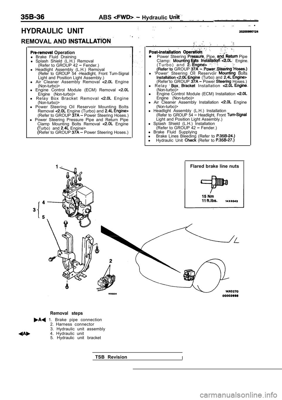
HYDRAULIC UNIT
ABS Hydraulic .
.
REMOVAL AND
.
Operationl Brake Fluid Draining
l Splash Shield (L.H.) Removal
(Refer to GROUP 42
Fender.)
l Headlight Assembly (L.H.) Removal
(Refer to GROUP 54 -Headlight, Front Turn-SignalLight and Position Light Assembly.)
l Air Cleaner Assembly Removal Engine(Non-turbo)>l Engine Control Module (ECM) Removal Engine (Non-turbo)>l R e l a y B o x B r a c k e t R e m o v a l E n g i n e(Non-turbo)>
Power Steering Pipe, Pipe
Clamp: Engine.( T u r b o ) a n d . GROUP l ‘Power‘ Steering Oil Reservoir Bolts (Turbo) and (Refer’to GROUP Power Hoses.)
l R e l a y Installation (Non-turbo)>l Engine Control Module (ECM) Installation Engine (Non-turbo)>l Air Cleaner Assembly Installation Engine(Non-turbo)>l Power Steering Oil Reservoir Mounting Bolts
Removal Engine (Turbo) and (Refer to GROUP Power Steering Hoses.)
l Power Steering Pressure Pipe and Return Pipe
Clamp Mounting Bolts Removal
EngineTurbo)and Engine>
Refer to GROUP Power Steering Hoses.) l
Headlight Assembly (L.H.) Installation
(Refer to GROUP 54 Headlight, Front Light and Position Light Assembly.)
l Splash Shield (L.H.) Installation
(Refer to GROUP 42
Fender.)
l Brake Fluid Supplying
l Brake Lines Bleeding (Refer to
lHydraulic Unit (Refer to
Flared brake line nuts
Removal steps
1. Brake pipe connection2.Harness connector
3. Hydraulic unit assembly
4. Hydraulic unit 5. Hydraulic unit bracket
TSB Revision
I
Page 1792 of 2103
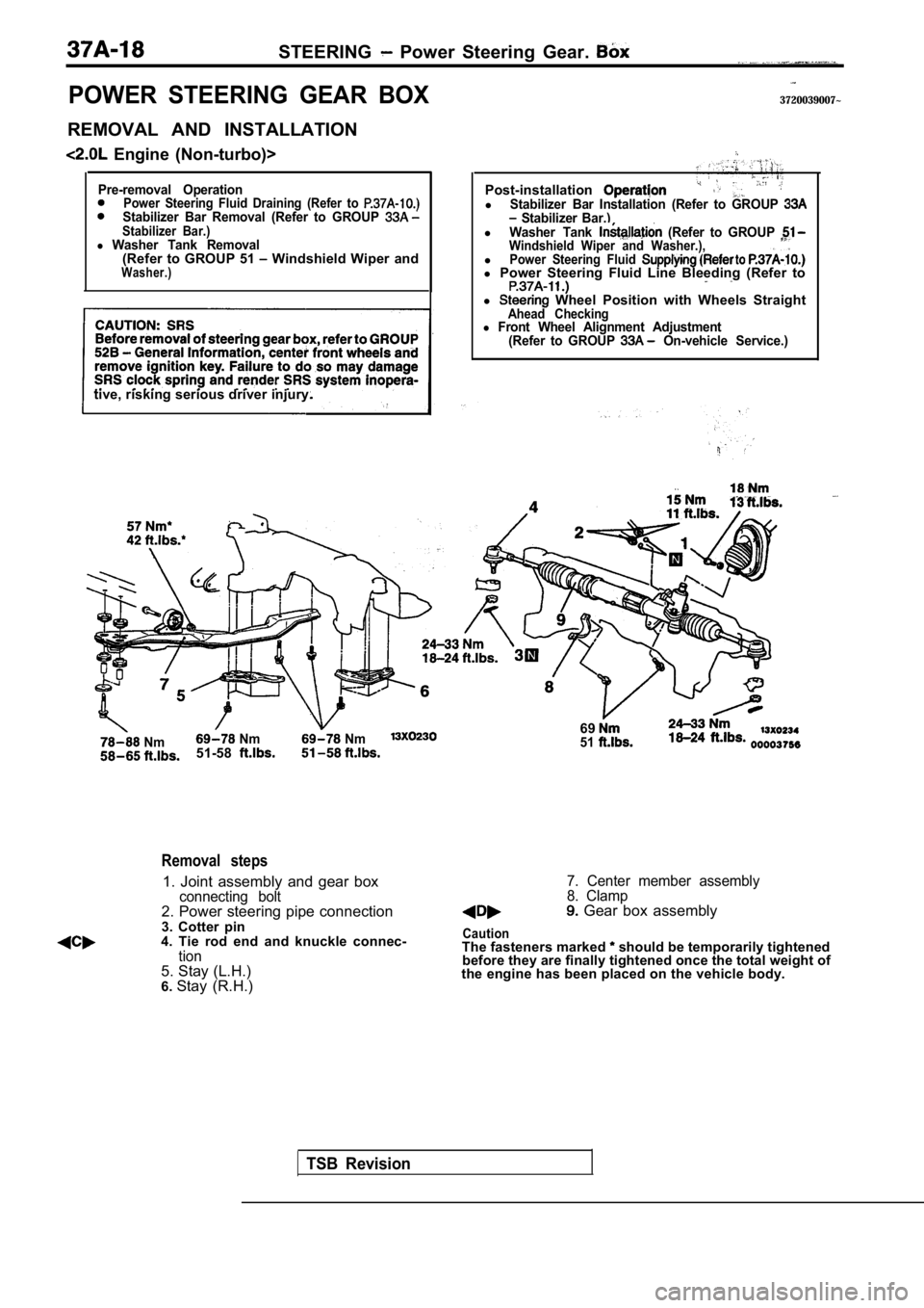
STEERING Power Steering Gear.
POWER STEERING GEAR BOX
REMOVAL AND INSTALLATION
Engine (Non-turbo)>
Pre-removal OperationPower Steering Fluid Draining (Refer to Stabilizer Bar Removal (Refer to GROUP Stabilizer Bar.)l Washer Tank Removal(Refer to GROUP 51 Windshield Wiper andWasher.)
tive, risking serious driver injury.
Nm Nm Nm51-58
3720039007~
TSB Revision
Removal steps
1. Joint assembly and gear boxconnecting bolt2. Power steering pipe connection
3. Cotter pin
4. Tie rod end and knuckle connec-
tion5. Stay (L.H.)
6. Stay (R.H.) Post-installation
lStabilizer Bar Installation (Refer to GROUP Stabilizer Bar.)lWasher Tank (Refer to GROUP Windshield Wiper and Washer.),lPower Steering Fluid l
Power Steering Fluid Line Bleeding (Refer to
l Wheel Position with Wheels StraightAhead Checkingl Front Wheel Alignment Adjustment
(Refer to GROUP On-vehicle Service.)
6951
7. Center member assembly
8. Clamp
Gear box assembly
CautionThe fasteners marked should be temporarily tightened
before they are finally tightened once the total we ight of
the engine has been placed on the vehicle body.
Page 1918 of 2103
BODY Electric Convertible Top
CONVERTIBLE TOP FIT ADJUSTMENT
(1) Remove the quarter trim, lower (Refer to GROUP
Trims.)
(2) Fully open orclose the top, then adjust the stopper
adjusting bolt so it contacts the flange as shown in the
illustration.
CONVERTIBLE TOP ASSEMBLY
REMOVAL AND INSTALLATION
Pre-removal OperationCompletely open the convertible top.Post-installation OperationConvertible top fit adjustment
8
View A
18
View A
76 7
5
Removal steps
3. Strip
l
Quarter belt moulding
(Refer to GROUP 51
Mouldings.) Quarter trim, lower
(Refer to GROUP Trims.)l Rear speaker(Refer to GROUP 54 Speaker.)
1. drive motor connector
2. Clip
4. Side attaching hook5. Defogger connectorl (Refer to GROUP
6. Rear strap
7. Drain trough rear attaching clip
8. Convertible top assembly
TSBRevision