Page 48 of 2103

GENERAL Maintenance
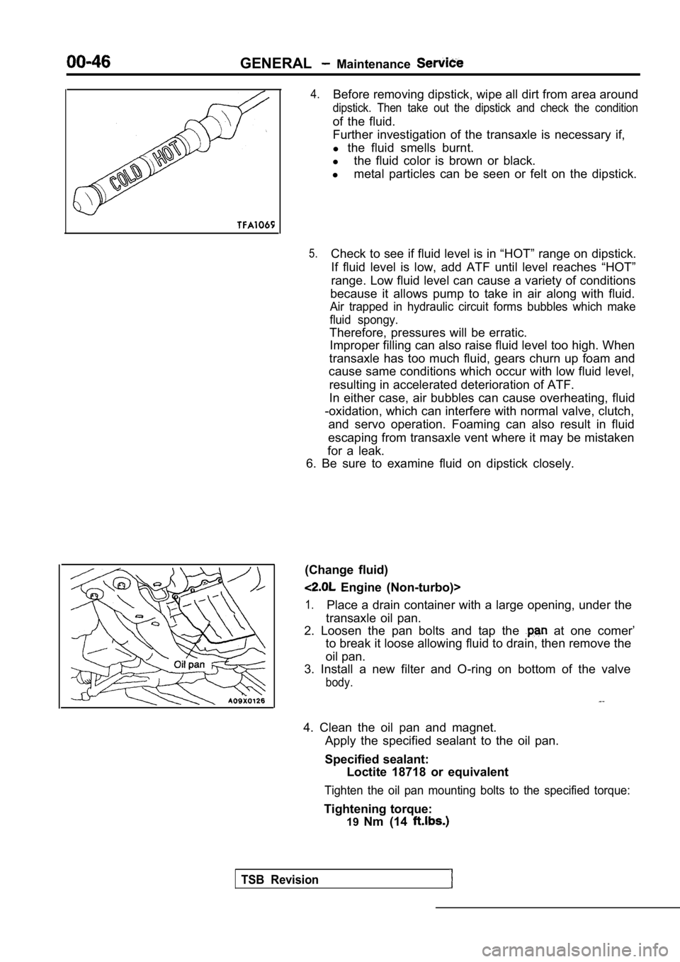
4.Before removing dipstick, wipe all dirt from area around
dipstick. Then take out the dipstick and check the condition
of the fluid.
Further investigation of the transaxle is necessary if,
l the fluid smells burnt.
l the fluid color is brown or black.
l metal particles can be seen or felt on the dipstick .
5.Check to see if fluid level is in “HOT” range on dipstick.
If fluid level is low, add ATF until level reaches “HOT”
range. Low fluid level can cause a variety of condi tions
because it allows pump to take in air along with fl uid.
Air trapped in hydraulic circuit forms bubbles which make
fluid spongy.
Therefore, pressures will be erratic. Improper filling can also raise fluid level too hig h. When
transaxle has too much fluid, gears churn up foam a nd
cause same conditions which occur with low fluid le vel,
resulting in accelerated deterioration of ATF.
In either case, air bubbles can cause overheating, fluid
-oxidation, which can interfere with normal valve, clutch,
and servo operation. Foaming can also result in flu id
escaping from transaxle vent where it may be mistak en
for a leak.
6. Be sure to examine fluid on dipstick closely.
(Change fluid)
Engine (Non-turbo)>
1.Place a drain container with a large opening, under the
transaxle oil pan.
2. Loosen the pan bolts and tap the
at one comer’
to break it loose allowing fluid to drain, then rem ove the
oil pan.
3. Install a new filter and O-ring on bottom of the valve
body.
4. Clean the oil pan and magnet.
Apply the specified sealant to the oil pan.
Specified sealant: Loctite 18718 or equivalent
Tighten the oil pan mounting bolts to the specified torque:
Tightening torque:
19Nm (14
TSB Revision
Page 49 of 2103

GENERALMaintenance Service
5.Add 3.8 (4.0 qts.) of the specified transmission fluid
through the filler tube.
Specified fluid:DIAMOND ATF SP IIor equivalent
6. Start the engine and allow it to run at idle for at least
one minute. Then, with parking and service brake ap plied,
move the selector lever momentarily to each positio n,
ending in the park or neutral position.
7.Add sufficient fluid to bring to’ inch below the
ADD mark.
8.Recheck fluid level after is normal operating
temperature. The level should be in the HOT region.
Engine (Turbo) and Engine>
Drain the fluid and check whether there is any evid ence of
contamination.
Refill with new fluid after the cause of any contam ination
has been corrected.
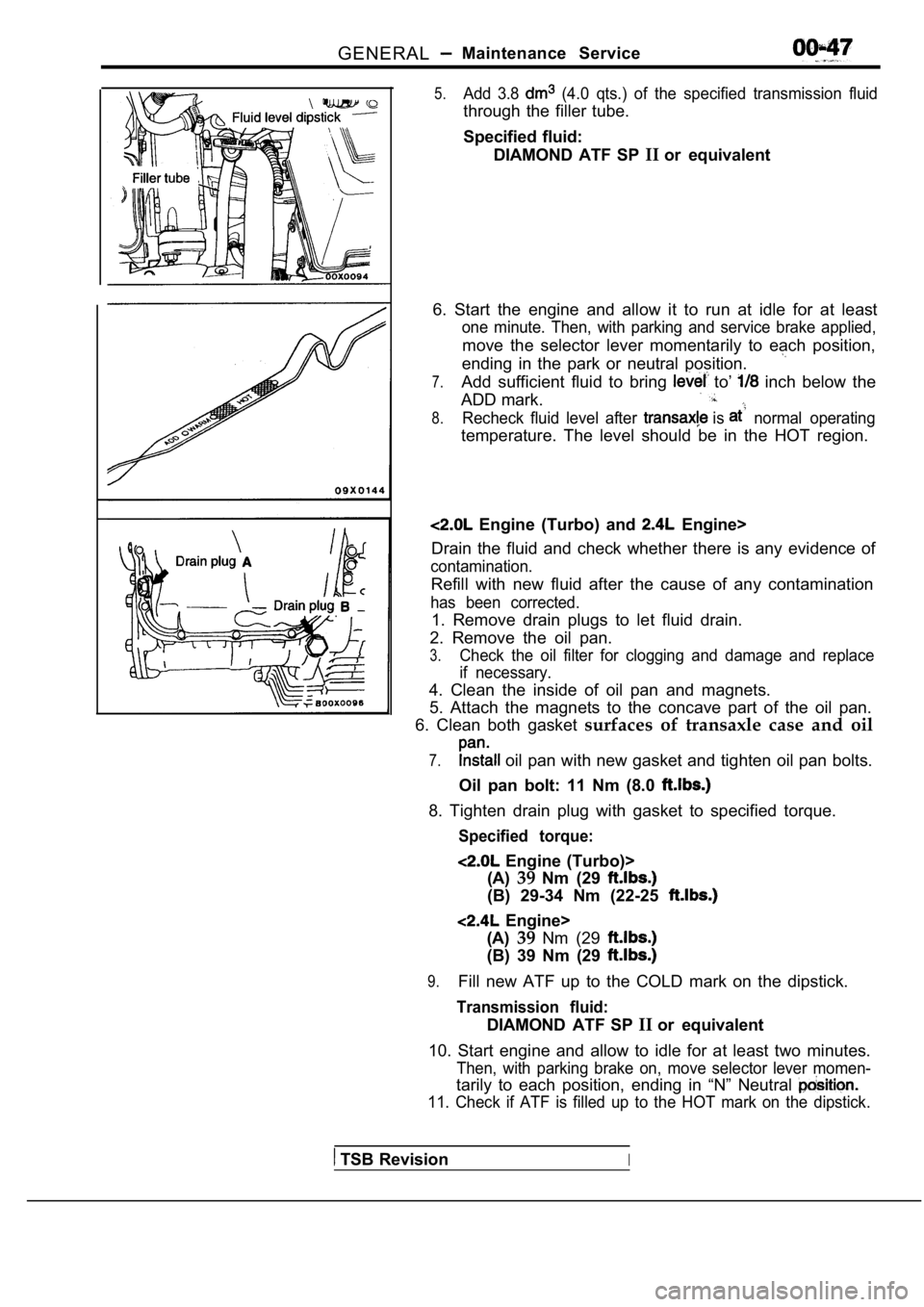
1. Remove drain plugs to let fluid drain.
2. Remove the oil pan.
3.Check the oil filter for clogging and damage and re place
if necessary.
4. Clean the inside of oil pan and magnets.
5. Attach the magnets to the concave part of the oi l pan.
6. Clean both gasket surfaces of transaxle case and oil
7. oil pan with new gasket and tighten oil pan bolts.
Oil pan bolt: 11 Nm (8.0
8. Tighten drain plug with gasket to specified torq ue.
Specified torque:
Engine (Turbo)>
(A) 39Nm (29
(B) 29-34 Nm (22-25
Engine>
(A) 39Nm (29
(B) 39 Nm (29
9.Fill new ATF up to the COLD mark on the dipstick.
Transmission fluid:
DIAMOND ATF SP IIor equivalent
10. Start engine and allow to idle for at least two minutes.
Then, with parking brake on, move selector lever mo men-
tarily to each position, ending in “N” Neutral
11. Check if ATF is filled up to the HOT mark on the dipstick.
TSB RevisionI
Page 146 of 2103
ENGINE OVERHAUL.
FRONT CASE, COUNTERBALANCE SHAFT AND OIL
REMOVAL AND INSTALLATION
1 3 1
24 Nm17
10 Nm
I18I I
76
17 Nm
19 Nm 101 4
45 Nm
33. . Nm
17I
10 Nm19 Nm14
40 Nm
5
Removal steps
Oil filter
2. Oil cooler bolt
3. Oil cooler
4. Drain plug
5. Drain plug gasket
6. Oil pan
7.Oil screen
8. Oil screen gasket
9. Baffle plate 10. Plug11. O-ring 12. Flange bolt 13. Oil pressure switch 14. Oil pressure gauge unit15. Relief plug
16. Gasket 17. Relief spring
18. Relief plunger
TSB Revision 19. Oil filter bracket
20. Oil filter bracket gasket
21. Oil pump cover
22. Oil pump driven gear 23. Oil pump drive gear 24. Crankshaft front oil seal
25. Oil pump oil seal 26. Counterbalance shaft oil seal 27. Front case
28. Front case gasket
29. Counterbalance shaft, left
30. Counterbalance shaft, right
31. Counterbalance shaft, front 32. shaft, rear
33. shaft, rear bearing,
Page 152 of 2103
Front Case, ENGINE OVERHAUL Shaft and. Pan
Crank pulley side
8 mm bolts
Oil pan viewed from lower side
Drain pigasket
P A N .
(1) Clean both mating surfaces of and cylinder block.
(2) Apply a 4 mm in.) wide bead of to the entire
circumference of the oil pan flange.
Specified sealant:
MITSUBISHI GENUINE or
equivalent
NOTE. .
Be sure to install the oil pan quickly the sealant’
is wet (within 15 minutes);
(2) After installation, keep the sealed area
from,,
the oil and coolant for approx.
hour.
, .
(3) Note the difference in bolt lengths at the loca
tion
DRAIN PLUG GASKET INSTALLATION
Install the drain plug gasket in the direction show n in the
illustration.
OIL COOLER INSTALLATION
First insert the oil cooler projecting stopper in t he oil filter
bracket groove and then tighten the oil cooler
TSB Revision
Page 293 of 2103
ENGINE Oil Pan and Oil
Draingasket Oil pan side
OIL PAN REMOVAL
After removing the oil pan remove the oil
pan with the special tool and
abrass
Caution
Do it slowly to avoid deformation of oil flange.
INSTALLATION SERVICE POINTS
OIL PAN INSTALLATION
Caution
After cleaning the oil bolt holes the
seal case, the oil’ pan should be
GASKET INSTALLATION
Replace the gasket and install, it in the in
the illustration.
TSB Revision
Page 350 of 2103
Front Case, ENGINE OVERHAUL Shaft and
FRONT CASE, COUNTERBALANCE SHAFT AND OIL
REMOVAL AND INSTALLATION
q 27 during reassembly.
2417
107
23
q 24
I
16
I
I1914
24. .
17
Removal steps
1. Oil filter2.Drain plug 3. Drain plug gasket 4. Oil pan5.Oil screen
6. Oil screen gasket
7. P l u g8.O-ring 9. Flange bolt 10. Oil pressure switch11.Relief plug12.Gasket13.Relief spring14.Relief plunger15. Oil filter bracket
16. Oil filter bracket gasket 19
14
I
l b7
75
17. Oil pump cover 18. Oil pump driven gear 19. Oil drive gear 20. Crankshaft front oilseal
21. Oil pump oil seal 22. Counterbalance shaft oil seal 23. Front case
24. Front case gasket
25. Counterbalance shaft, left
26. Counterbalance shaft, right
27. Counterbalance shaft, front bearing 28. shaft, rear
29. shaft, rear bearing,
TSB Revision
Page 377 of 2103
ENGINE LUBRICATION Oil Cooler
ENGINE OIL COOLER 12100130117
REMOVAL AND INSTALLATION
Operationl Engine Coolant Draining(Refer to GROUP 00 Maintenance
Engine oil
Engine Oil Checking and Supplying
2
Removal steps
1. Oil filter
2. Water hose connection
3. Oil cooler bolt
4. Engine oil cooler
Oil filter bracket
Stopper
Engine oil cooler
INSTALLATION SERVICE POINT
ENGINE OIL COOLER INSTALLATION
the stopper into the groove of the oil filter bracket,
and then tighten the oil cooler bolt.
TSB Revision
Page 732 of 2103
INTAKE AND EXHAUST Exhaust Manifold
E X H A U S T M A N I F O L D E N G I N E ( T U R B O ) >
REMOVAL AND INSTALLATION
Pre-removal and Post-installation OperationEngine Coolant Draining and Refilling
l Engine Oil Draining and Refilling
(Refer to GROUP 00
Maintenance Service.)
Nm
12-15 Nm8.8-11- - 1 6 ’
3
. .
Removal steps
1. Condenser fan motor assembly with air conditioning>
2. Heated oxygen sensor
3. Engine oil level gauge guide
4. Air cleaner and air intake hose
assembly5. Air hose (A) connection
6. Water hose connection
7. Water hose connection
8. Oil pipe (A) connection 9. Heat protector
A)
10. Heat protectorB)
11. Engine hanger
12. Front exhaust pipe connection 13. Flange bolts 14. Flange 15.
Coned disc spring .16. Exhaust -manifold17.Exhaust manifold gasket Ring19. Gasket (A)
TSB Revision