Page 1606 of 2103
FRONT SUSPENSION Upper Arm .
UPPER ASSEMBLY
REMOVAL AND INSTALLATION
Post-installation OperationFront Wheel Alignment Adjustment(Refer to
5741
Removal steps
1. Upper arm ball joint and knuckleconnection2. Upper arm self-locking nut3. Upper arm assembly
4. Upper arm shaft assembly
Nut
Upper arm shaft
REMOVAL SERVICE ‘POINT
ARM BALL AND
Caution
1.Use the special tool to loosen the
loosen the nut: do not from the
2. the special tool with cord; etc. to prevent
it from coming
INSTALLATION SERVICE POINT
UPPER ARM SHAFT ASSEMBLY INSTALLATION
Install the upper arm shaft assembly at the angle s hown
in the illustration.
NOTE
If the upper arm shaft is installed at the above-me ntioned
angle, the reference dimension is determined as fol lows;
TSB Revision
Page 1608 of 2103
F R O N T S U S P E N S I O N Upper Arm . ,
UPPER ARM BALL DUST COVER
REPLACEMENT
Replace the dust cover by the following procedure o nly if
the
has become damaged by accident during
servicing.
(1) Remove the dust cover.
(2) Apply multipurpose grease to the lip and
the
dust cover.
(3) the dust cover with tool until it is fully
.
SHOCK ABSORBER ASSEMBLY
REMOVAL AND INSTALLATION
I,Post-installation OperationFront Wheel Alignment Adjustment
(Refer to
8865
4432
65
Removal steps
1. Stabilizer link mounting nut
2. Shock absorber upper mounting
nuts
5. Damper fork
6. Shock absorber assembly
3. Shock absorber lower mounting
bolt4. Damper fork mounting bolt
Cautionl :Indicates parts which should be tightened,and then fully tightened the veh on the groundin the unladen condition.
TSB Revision
Page 1617 of 2103
REAR
SUSPENSION-
CONTENTS
GENERAL INFORMATION2SHOCK ABSORBER ASSEMBLY. . . . . . . . . . .. . . . . . . . . . . . . . . . ..
LOWER ARM AND TOE CONTROL ARMSPECIAL TOOLS. . . . . . . . . . . . . . . . . . . . . . . . . .4
ASSEMBLIES. . . . . . . . . . . . . . . . . . . . . . . . . . . . .12
STABILIZER BAR. . . . . . . . . . . . . . . . . . . . .
REAR SUSPENSION ASSEMBLY. . . . . . . . . .7.
TRAILING ARM . . . . . . . . . . . . . . . . .11
ON-VEHICLE SERVICE. . . . . . . . . . . . . . . . . . . .6
Rear Wheel Alignment Check. . . . . . . . . . . . . . . . . . . . . .6
and Adjustment
. . . . . . . . . . . . . . . . . . . . . . . . . . . . .6UPPER ARM ASSEMBLY. . . . . . . . . . . . . . . . . . . .9
SERVICE SPECIFICATIONS . . . . . . . . . . . . . . . .
4
Page 1622 of 2103
34-6REAR SUSPENSION Service
REAR WHEEL
ADJUSTMENT,Measure. wheel alignment with
ground.
The rear suspension and be serviced to the
normal condition prior to wheel alignment.
. .
T O E - I N
Standard 3 3 mm. in.)
Turn the toe control arm bolt to the left or right
by equal amounts to adjust..
L.H.: Turning clockwise toe-out direction
R.H.: Turning clockwise toe-in
Furthermore, toe adjustment can be made at graduati ons
of
1.3 mm tn.).
CAMBER’
Standard value:
(Vehicles with wheels)
wheels), AWD
NOTE
1.Camber is preset at the’factory and can not be adju sted.
2. If is not within the, standard value, check and
bent or
TSB Revision
Page 1625 of 2103
REAR SUSPENSION Upper ‘Arm
U P P E R A R M A S S E M B L Y
REMOVAL AND INSTALLATION
Post-installation Operationl Wheel Alignment Check and Adjustment(Refer to
457Nm
57Nm
41
39 Nm
Removal steps
1. Upper arm and knuckle connecting
bolt2. arm assembly mounting
3. Upper arm assembly
4. Upper arm bracket
CautionIndicates parts which should be temporarily tighten ed,and then fulltightened with the on the groundin the unlaen condition.
TSB Revision
Page 1628 of 2103
2 REAR SUSPENSION Lower Arm and Toe
LOWER ARM AND TOE CONTROL ARM ASSEMBLIES
REMOVAL AND INSTALLATION
Post-installation OperationlWheel Alignment Check and Adjustment
(Refer to , ,
89-78
39 Nm
Lower arm assembly removal steps
1. Lower arm cover
2. Stabilizer link ball joint and lower
arm connection3. ABS wheel-speed sensor clamp
bolts
with 4. Lower arm assembly and knuckleconnecting bolt5. Lower arm assembly mounting bolt
6. Lower arm assembly Toe
control arm assembly removal
steps
7. Toe control arm ball joint andknuckle , 6. control mounting
9. arm ,
Cautionl Indicates which should tightened,
and then fully with on the groundin the unladen
Cord
REMOVAL’ SERVICE POINTS
CONTROL ARM BALL JOINT AND
KNUCKLE DISCONNECTION
Caution
1.Be sure to tie the cord of the special tool to a ne arby
part.
2. Loosen the nut but do not remove it.
T S B. .
Page 1790 of 2103

6STEERING Steering Wheel , .
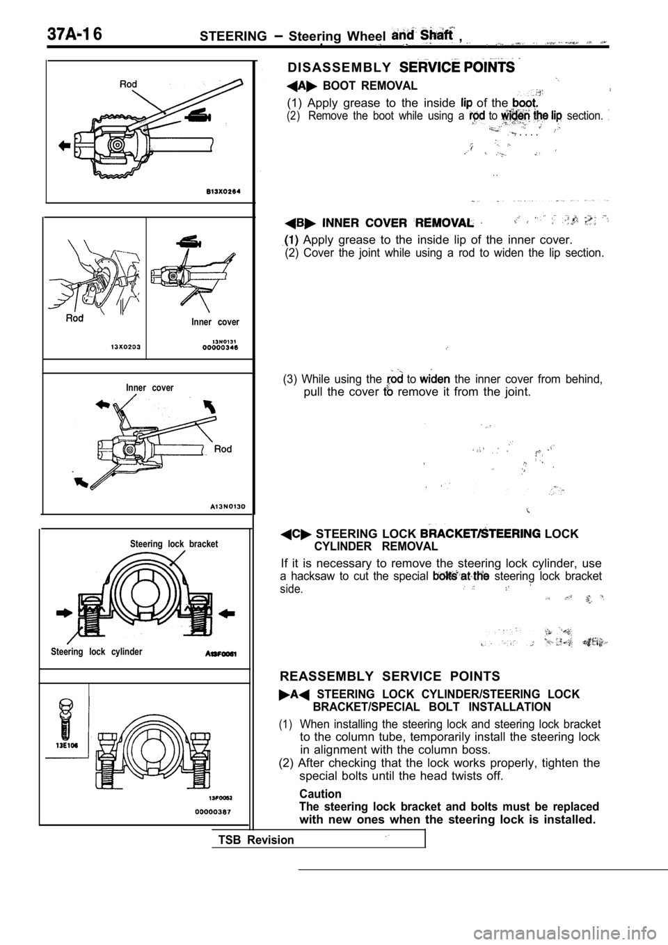
Inner cover
Inner cover
Steering lock bracket
Steering lock cylinder
D I S A S S E M B L Y
BOOT REMOVAL
(1) Apply grease to the inside of the
(2)Remove the boot while using a to section.
. . . .
. .
Apply grease to the inside lip of the inner cover.
(2) Cover the joint while using a rod to widen the lip section.
(3) While using the to the inner cover from behind,
pull the cover remove it from the joint.
TSB Revision
STEERING LOCK LOCK
CYLINDER REMOVAL
If it is necessary to remove the steering lock cylinder, use
a hacksaw to cut the special steering lock bracket
side.
REASSEMBLY SERVICE POINTS
STEERING LOCK CYLINDER/STEERING LOCK
BRACKET/SPECIAL BOLT INSTALLATION
(1)When installing the steering lock and steering lock bracket
to the column tube, temporarily install the steering lock
in alignment with the column boss.
(2) After checking that the lock works properly, ti ghten the
special bolts until the head twists off.
Caution
The steering lock bracket and bolts must be replace d
with new ones when the steering lock is installed.
Page 1792 of 2103

STEERING Power Steering Gear.
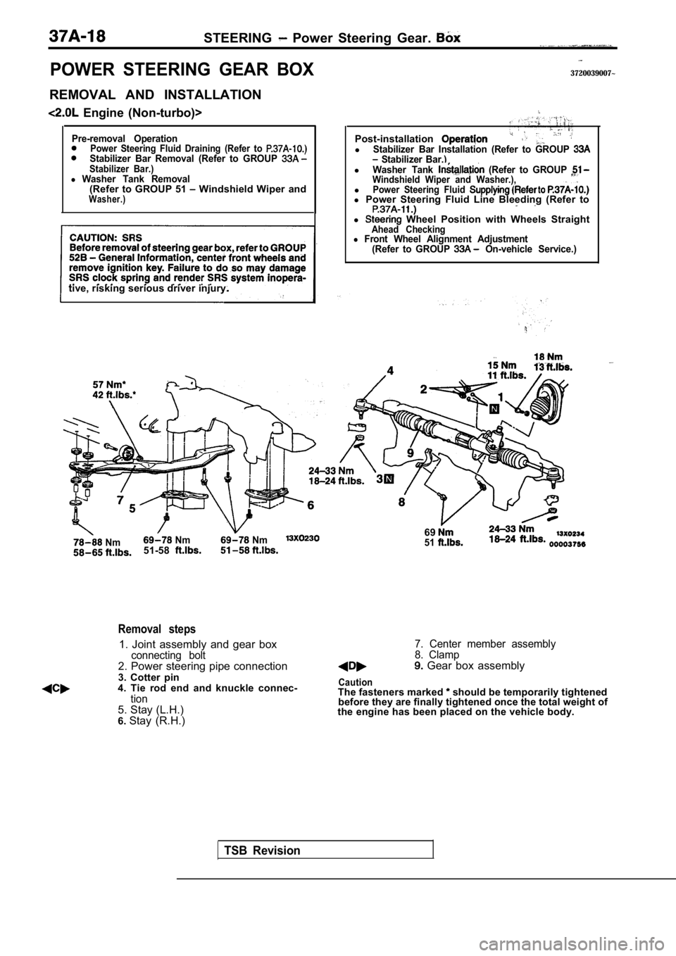
POWER STEERING GEAR BOX
REMOVAL AND INSTALLATION
Engine (Non-turbo)>
Pre-removal OperationPower Steering Fluid Draining (Refer to Stabilizer Bar Removal (Refer to GROUP Stabilizer Bar.)l Washer Tank Removal(Refer to GROUP 51 Windshield Wiper andWasher.)
tive, risking serious driver injury.
Nm Nm Nm51-58
3720039007~
TSB Revision
Removal steps
1. Joint assembly and gear boxconnecting bolt2. Power steering pipe connection
3. Cotter pin
4. Tie rod end and knuckle connec-
tion5. Stay (L.H.)
6. Stay (R.H.) Post-installation
lStabilizer Bar Installation (Refer to GROUP Stabilizer Bar.)lWasher Tank (Refer to GROUP Windshield Wiper and Washer.),lPower Steering Fluid l
Power Steering Fluid Line Bleeding (Refer to
l Wheel Position with Wheels StraightAhead Checkingl Front Wheel Alignment Adjustment
(Refer to GROUP On-vehicle Service.)
6951
7. Center member assembly
8. Clamp
Gear box assembly
CautionThe fasteners marked should be temporarily tightened
before they are finally tightened once the total we ight of
the engine has been placed on the vehicle body.