1990 MITSUBISHI SPYDER check engine light
[x] Cancel search: check engine lightPage 180 of 2103
ENGINE On-vehicle Service
POWER STEERING OIL PUMP AND A/C
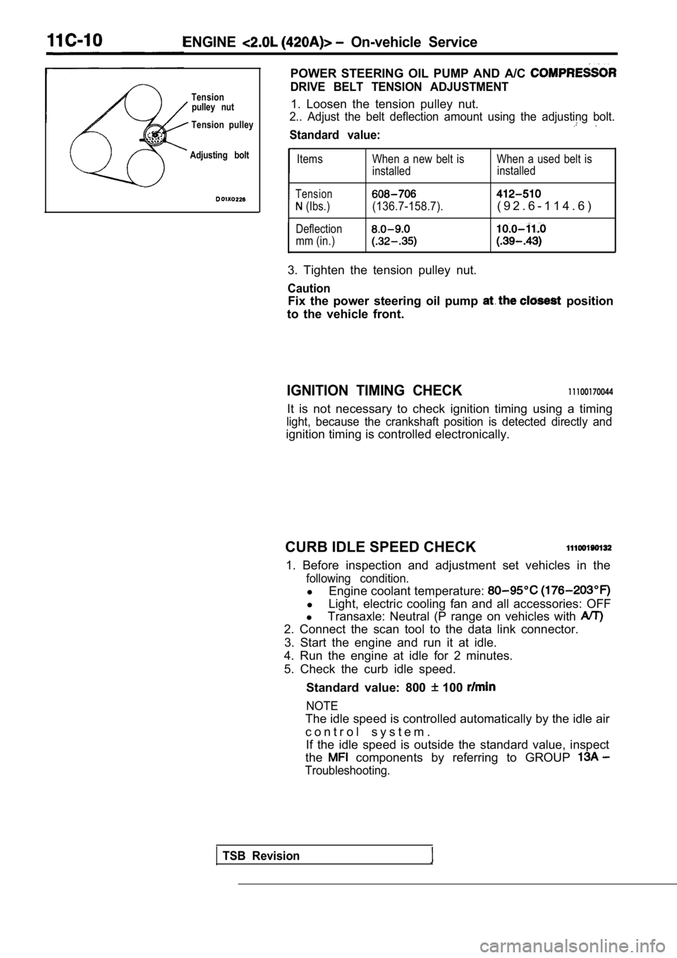
DRIVE BELT TENSION ADJUSTMENTTensionpulley nut1. Loosen the tension pulley nut.
Tension pulley2.. Adjust the belt deflection amount using the adj usting bolt.
Standard value:
Adjusting boltItems
Tension
(Ibs.)
Deflection
mm (in.) When a new belt is When a used belt is
installed
installed(136.7-158.7).( 9 2 . 6 - 1 1 4 . 6 )
3. Tighten the tension pulley nut.
Caution
Fix the power steering oil pump position
to the vehicle front.
IGNITION TIMING CHECK11100170044
It is not necessary to check ignition timing using a timing
light, because the crankshaft position is detected directly and
ignition timing is controlled electronically.
CURB IDLE SPEED CHECK
1. Before inspection and adjustment set vehicles in the
following condition.
lEngine coolant temperature:
lLight, electric cooling fan and all accessories: OF F
l Transaxle: Neutral (P range on vehicles with
2. Connect the scan tool to the data link connector .
3. Start the engine and run it at idle.
4. Run the engine at idle for 2 minutes.
5. Check the curb idle speed.
Standard value: 800
100
NOTE
The idle speed is controlled automatically by the i dle air
c o n t r o l s y s t e m . If the idle speed is outside the standard value, in spect
the
components by referring to GROUP
Troubleshooting.
TSB Revision
Page 181 of 2103

ENGINE On-vehicle Service
IDLE MIXTURE CHECK
11100210081
1.Before inspection, set vehicles in the following co ndition:
lEngine coolant temperature:
l Lights, electric cooling fan and all accessories: O FF
lTransaxle: Neutral (P range on vehicles with
2.After turning the ignition switch to OFF, connect t he scan
tool to the data link connector.
3.Start the engine and run it at 2,500 for 2 minutes.
4. Set the CO, HC tester.
5. Check the CO contents and the HC contents at idl e.
Standard value:
CO contents: 0.5% or less
HC contents: 100 ppm or less
6. If the idle speed is outside the standard value, check
the following items: l Diagnostic output
l Closed-loop control (When the closed-loop control
is carried out normally, the output signal of the h eated
oxygen sensor repeats between and
,000 at idle.)
l Fuel pressure
I n j e c t o r
lIgnition coil, spark plug cable, spark plug
lEGR system and the EGR valve leak
l Evaporative emission control system
Compression pressure
NOTE
Replace the three-way catalyst whenever the CO and
HC contents do not remain inside the standard value .
(even though the result of the inspection is normal on
all items.)
COMPRESSION PRESSURE CHECK
1.Before inspection, check that the engine oil, start er and
battery are normal. Also, set the vehicle to the fo llowing
condition:
lEngine coolant temperature:
lLights, electric cooling fan and all accessories: O FF
lTransaxle: Neutral (P range on vehicle with
2. Disconnect the spark plug cables.
3. Remove all spark plugs.
4.Disconnect the relay (ASD relay) connector to prevent
a spark.
4 4
Revision
Page 183 of 2103
ENGINE On-vehicle.’
M A N I F O L D V A C U U M
1.Before inspection, set vehicles. in the condition:
Engine coolant
lLights, electric cooling and
lTransaxle: Neutral (P
2. Connect the scan tool to the data link connector.
,
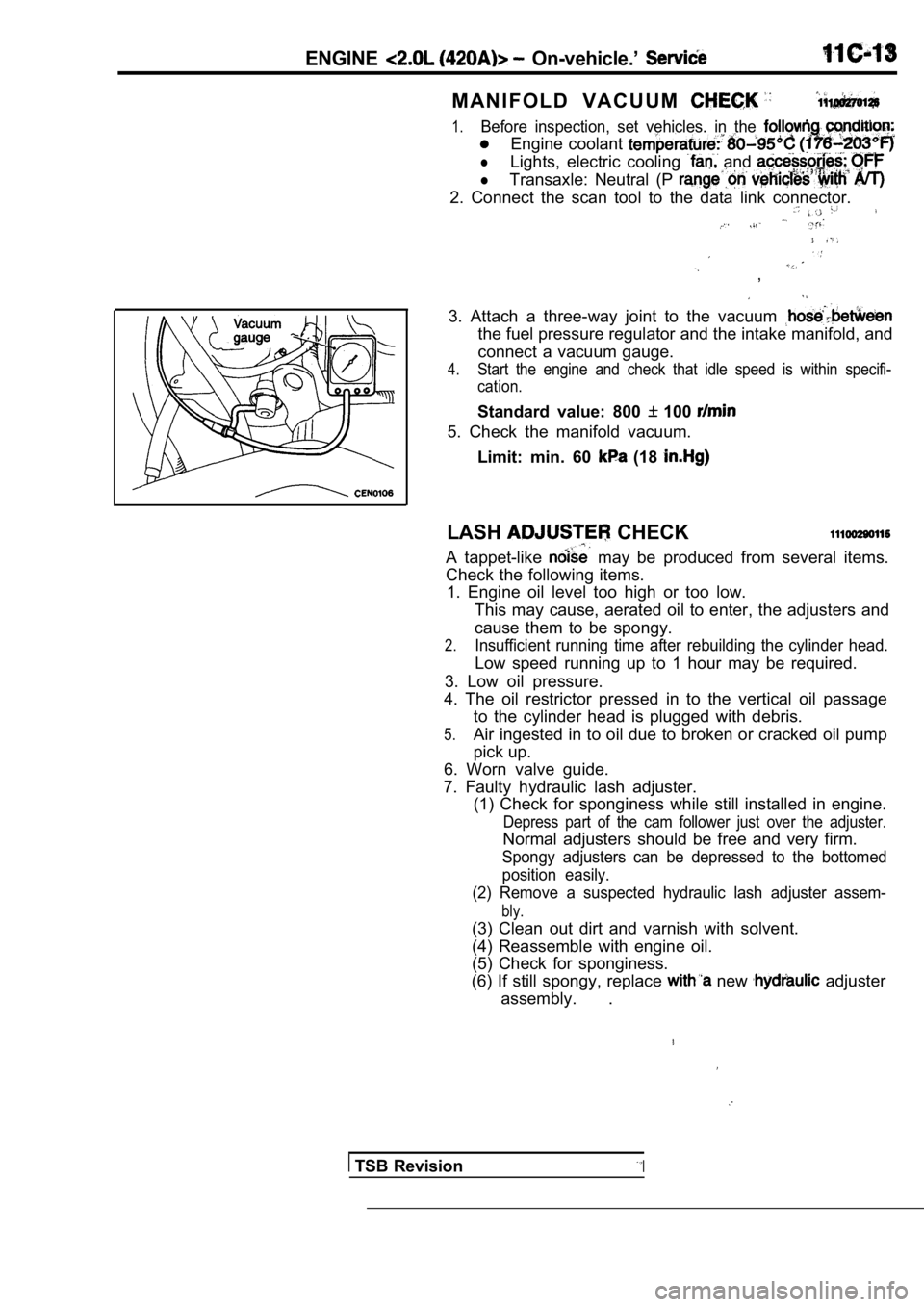
3. Attach a three-way joint to the vacuum
the fuel pressure regulator and the intake manifold, and
connect a vacuum gauge.
4.Start the engine and check that idle speed is withi n specifi-
cation.
Standard value: 800 100
5. Check the manifold vacuum.
Limit: min. 60
(18
LASH CHECK
A tappet-like may be produced from several items.
Check the following items. 1. Engine oil level too high or too low.
This may cause, aerated oil to enter, the adjusters and
cause them to be spongy.
2.Insufficient running time after rebuilding the cyli nder head.
Low speed running up to 1 hour may be required.
3. Low oil pressure.
4. The oil restrictor pressed in to the vertical oi l passage
to the cylinder head is plugged with debris.
5.Air ingested in to oil due to broken or cracked oil pump
pick up.
6. Worn valve guide.
7. Faulty hydraulic lash adjuster. (1) Check for sponginess while still installed in e ngine.
Depress part of the cam follower just over the adju ster.
Normal adjusters should be free and very firm.
Spongy adjusters can be depressed to the bottomed
position easily.
(2) Remove a suspected hydraulic lash adjuster asse m-
bly.
(3) Clean out dirt and varnish with solvent.
(4) Reassemble with engine oil.
(5) Check for sponginess.
(6) If still spongy, replace
new adjuster
assembly. .
TSB RevisionI
Page 228 of 2103
11 ENGINE OVERHAUL Cooling System
(1) Install switch.
(2) Install engine coolant
lighten sensor
to 7 Nm (5
torque.
Overflownipple
Pressure cap
Impeller
TSB Revision
O-ring
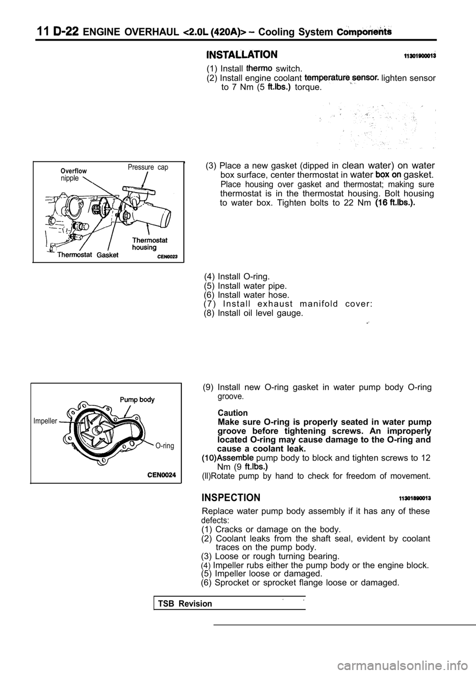
(3) Place a new gasket (dipped in clean water) on water
box surface, center thermostat in water
gasket.
Place housing over gasket and thermostat; making su re
thermostat is in the thermostat housing. Bolt housing
to water box. Tighten bolts to 22 Nm
(4) Install O-ring.
(5) Install water pipe.
(6) Install water hose.
( 7 ) I n s t a l l e x h a u s t m a n i f o l d c o v e r :
(8) Install oil level gauge.
(9) Install new O-ring gasket in water pump body O- ring
groove.
Caution
Make sure O-ring is properly seated in water pump
groove before tightening screws. An improperly
located O-ring may cause damage to the O-ring and
cause a coolant leak.
pump body to block and tighten screws to 12
Nm (9
(ll)Rotate pump by hand to check for freedom of mov ement.
INSPECTION
Replace water pump body assembly if it has any of these
defects:
(1) Cracks or damage on the body.
(2) Coolant leaks from the shaft seal, evident by c oolant
traces on the pump body.
(3) Loose or rough turning bearing.
(4) Impeller rubs either the pump body or the engine bl ock.
(5) Impeller loose or damaged.
(6) Sprocket or sprocket flange loose or damaged.
Page 277 of 2103
On-vehicle Service
A/C COMPRESSOR DRIVE BELT TENSION ADJUSTMENT
1. Loosen tension pulley fixing nut A.
2. Adjust belt tension with adjusting bolt B.
Standard value:
When a new belt isWhen a used belt is
installed installed
Tension
382-411255-333
(Ibs.)
Deflection8.5-7.5
mm (in.)
3. Tighten fixing nut A. Tightening torque: 23-26 Nm
4.Check the belt deflection amount and readjust if ne ces-
sary.
Caution
This check should be carried out after turning the
crankshaft one full rotation or more
the forward
direction (to the right).
IGNITION TIMING CHECK
1.Before inspection and adjustment set vehicle in the follow-
ing condition.
lEngine coolant temperature:
lLights, electric cooling fan and all accessories: OFF
Transaxle: Neutral (P range on vehicles with
2. Turn the ignition switch to OFF and connect the scan
tool to the data link connector.
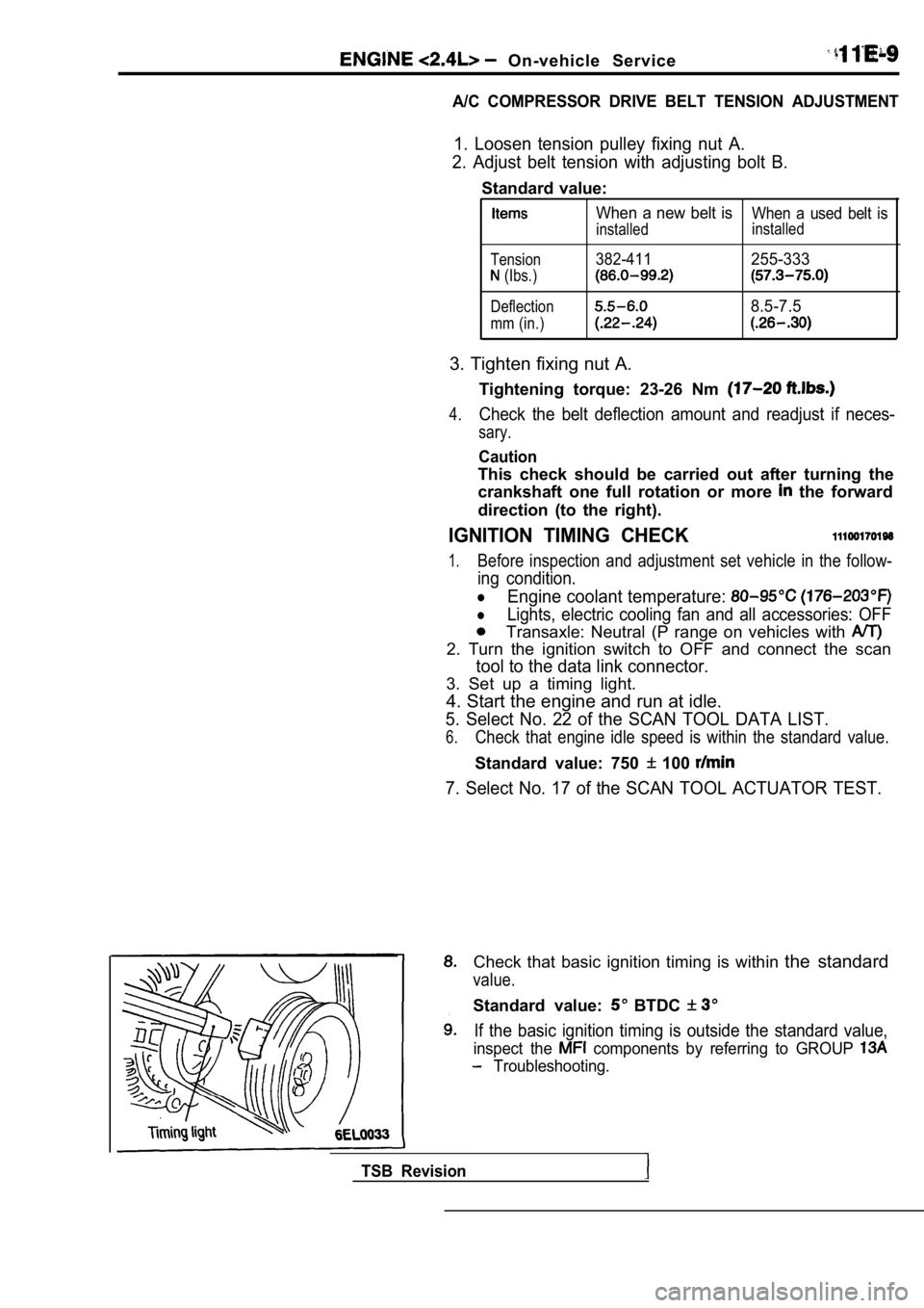
3. Set up a timing light.
4. Start the engine and run at idle.
5. Select No. 22 of the SCAN TOOL DATA LIST.
6.Check that engine idle speed is within the standard value.
Standard value: 750 100
7. Select No. 17 of the SCAN TOOL ACTUATOR TEST.
Check that basic ignition timing is within the standard
value.
Standard value: BTDC
If the basic ignition timing is outside the standar d value,
inspect the components by referring to GROUP
Troubleshooting.
TSB Revision
Page 278 of 2103
ENGINE O n - v e h i c l e
Press the scan tool clear key (select aforced driving
cancel mode) to release the ACTUATOR TEST
NOTE
If the test is not a forced driving will continue
for 27 minutes. Driving under this condition may damage
the engine.
Check that the actual ignition timing is at the st andard
value.
Standard value: Approx. BTDC
NOTE
Ignition timing is variable within about even under
normal operating.
2. And it is automatically further advanced by abou t
from BTDC at higher altitudes.
CURB IDLE SPEED CHECK
Before inspection and adjustment, set vehicles in the
following condition.
lEngine coolant temperature:
lLights, electric cooling fan and all accessories: OFF
lTransaxle: Neutral (P range on vehicles with A/T)
2. Turn the ignition switch to OFF and connect the scan
tool to the data link connector.
3. Select No. 17 of the SCAN TOOL ACTUATOR TEST
4. Check the basic ignition timing.
Standard value: BTDC
5. Run the engine at idle for 2 minutes.
6. Select No. 22 of the SCAN TOOL DATA LIST.
7. Check the curb idle speed.
Standard value: 750 100
NOTE
The idle speed is controlled automatically by the i dle air
control system.
8. If the idle speed is outside the standard value, check
the components by referring to GROUP Trou-
bleshooting.
IDLE MIXTURE CHECK
Before inspection, set vehicles in the following co ndition:
lEngine coolant temperature:
lLights, electric cooling fan and all accessories: O FF
lTransaxle: Neutral (P range on vehicles with
2. Turn the ignition switch to OFF and connect the scan
tool to the data link connector.
3. Select No. 17 of the SCAN TOOL ACTUATOR TEST.
4.Check that the basic ignition timing is within the standard
value..
Standard value:
TSB Revision
Page 279 of 2103

On-vehicle
Run the engine.
8. Set CO, HC tester.
7. Check the CO contents and the HC contents at idle.
Standard value:
CO contents: 0.5% or less
HC contents: 100 ppm or less
8. the standard value is exceeded, check the following
items:
l Diagnostic output
l Closed-loop control (When the closed-loop control
is carried out normally, the output signal of the heated
oxygen sensor and
at idle.)
l
Injector
lIgnition coil, spark plug
l system the
l Evaporative emission
Compression ,
NOTE,
Replace the three-way CO and
HC contents do not
the value.
(even though the
of the” on
all items.)
PRESSURE CHECK
1.Before inspection, check that the engine oil, start er and
battery are normal. Also, set the vehicle to the fo llowing
condition:
lEngine coolant temperature:
lLights, electric cooling fan and all accessories: O FF
lTransaxle: Neutral (P range on vehicles with
2. Disconnect the spark plug cables.
3. Remove all of the spark plugs.
4. Disconnect the crankshaft position sensor
NOTE
Doing this will prevent the engine control unit fro m carrying
out ignition and fuel injection.
TSB Revision
Page 305 of 2103
E N G I N E Timing Belt
Timing marks
sprocket
mm
(2.36 in.)
or more .
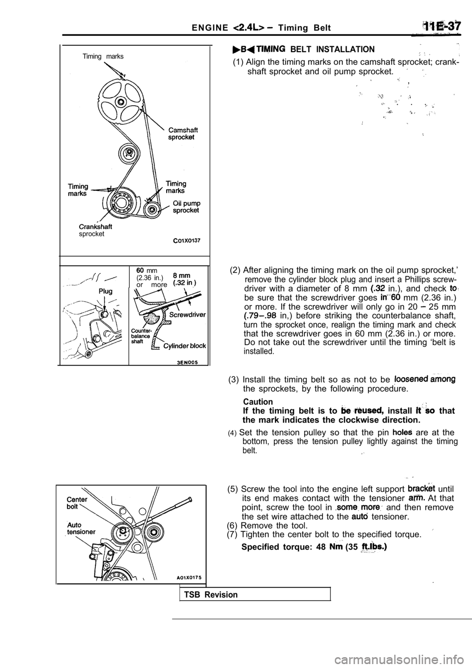
BELT INSTALLATION
(1) Align the timing marks on the camshaft sprocket ; crank-
shaft sprocket and oil pump sprocket.
,
. . .
(2) After aligning the timing mark on the oil pump sprocket,’
remove the cylinder block plug and insert a Phillips screw-
driver with a diameter of 8 mm in.), and check
be sure that the screwdriver goes mm (2.36 in.)
or more. If the screwdriver will only go in 20
25 mm
in,) before striking the counterbalance shaft,
turn the sprocket once, realign the timing mark and check
that the screwdriver goes in 60 mm (2.36 in.) or mo re.
Do not take out the screwdriver until the timing ‘b elt is
installed.
(3) Install the timing belt so as not to be
the sprockets, by the following procedure.
Caution
If the timing belt is to install that
the mark indicates the clockwise direction.
(4) Set the tension pulley so that the pin
are at the
bottom, press the tension pulley lightly against th e timing
belt.
TSB Revision
(5) Screw the tool into the engine left support until
its end makes contact with the tensioner
At that
point, screw the tool in
and then remove
the set wire attached to the
tensioner.
(6) Remove the tool.
(7) Tighten the center bolt to the specified torque .
Specified torque: 48 (35