Page 490 of 2103

ENGINE (NON-TURBO)>
INSPECTION PROCEDURE 44
Check the vehicle-speed sensor and speedometer.
Measure at the speed sensor connector l Disconnect the connector and measure at the harness side.
l Voltage between 1 and ground (Ignition switch: ON)
OK: 8.5-9.5
l Continuity between 2 and ground
OK: Continuity
OK
C h e c k t h e
Check the harness wire PCM and the speed connector. Repair, if necessary.
Check the followina connector: NG Repair
OK
Check trouble symptom.
NG
NG
Check the harness wire between the PCM and the spee d sensor Repairconnector.
SCAN TOOL SENSOR (Data list)65 Vehicle speed
l Is actual vehicle soeed indicated durina drivina?I
No
Check the speedometer circuit.
(Refer to INSPECTION PROCEDURE 45.)I
OK
Replace the vehicle speed sensor.
T S B R e v i s i o n
SCAN TOOL SENSOR READ TESTS (Data list)
65 Vehicle speed
l
Is actual vehicle speed indicated during driving?
No
Yes Replace the PCM.
. . .
NG I):
Repair. .
. -
Check trouble symptom. , .
NGCheck the harness wire between the PCM and the tran saxle control Repairmodule connector.
OK
INSPECTIONPROCEDURE 45.)
OK
Check the automatic transaxle control system.
Page 492 of 2103

ENGINE (NON-TURBO)> Troubleshooting
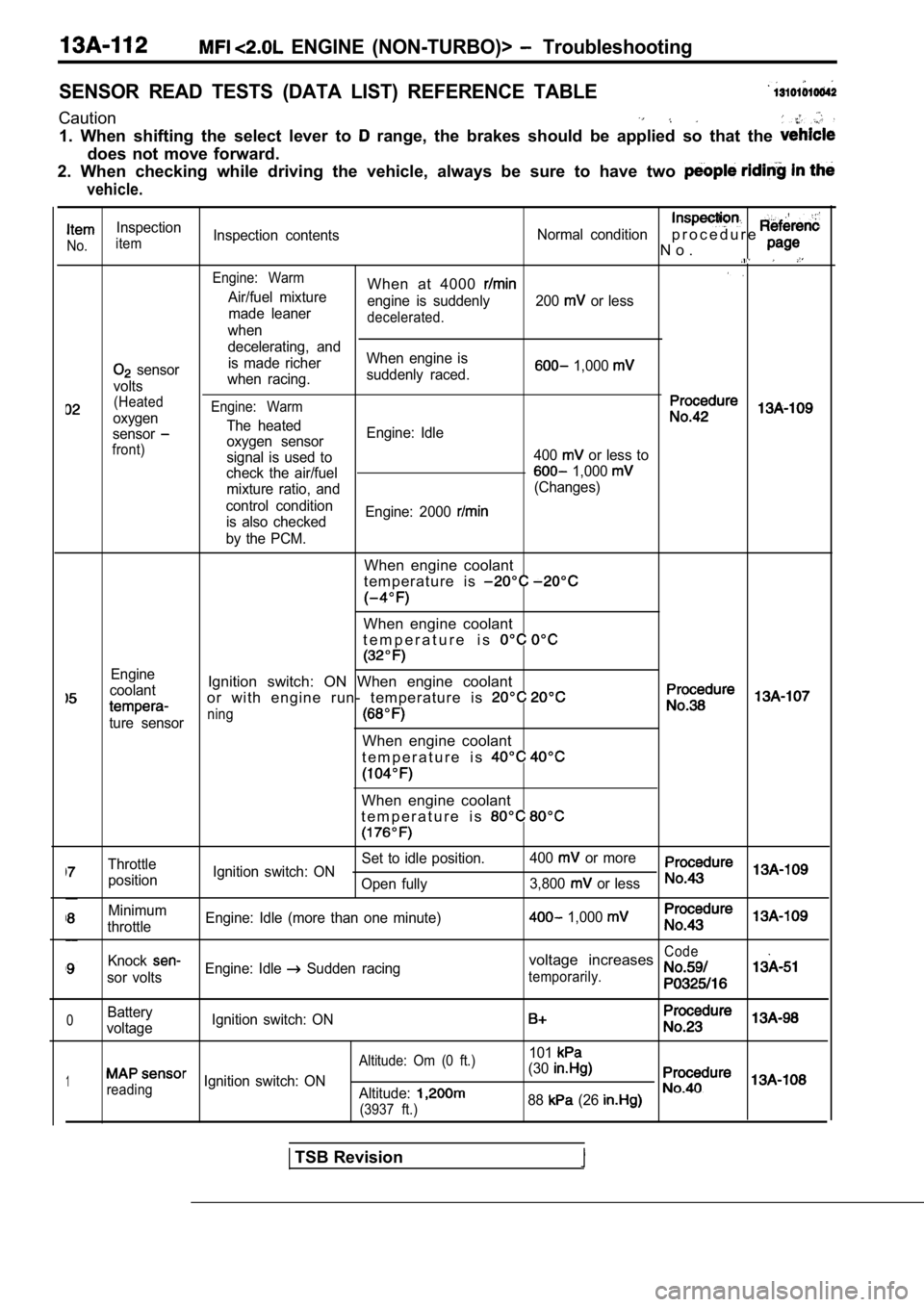
SENSOR READ TESTS (DATA LIST) REFERENCE TABLE
Caution
1. When shifting the select lever to range, the brakes should be applied so that the
does not move forward.
2. When checking while driving the vehicle, always be sure to have two
vehicle.
Inspection
No.itemInspection contents
Normal conditionp r o c e d u r e
N o .
Engine: WarmWhen at 4000 Air/fuel mixture
engine is suddenly 200 or less
made leaner
decelerated.when
decelerating, and
sensor is made richer
When engine is 1,000
voltswhen racing.
suddenly raced.
(Heated
oxygenEngine: Warm
The heatedsensoroxygen sensor Engine: Idlefront)signal is used to
400 or less to
check the air/fuel
1,000
mixture ratio, and (Changes)
control condition is also checked Engine: 2000
by the PCM.
When engine coolant
t e m p e r a t u r e i s
When engine coolant
t e m p e r a t u r e i s
Engine
coolantIgnition switch: ON When engine coolant
or with engine run- temperature is
ture sensorning
When engine coolant
t e m p e r a t u r e i s
When engine coolant
t e m p e r a t u r e i s
Throttle Set to idle position.
400 or more
position Ignition switch: ON
Open fully 3,800
or less
Minimum
throttle Engine: Idle (more than one minute) 1,000
KnockCode
sor voltsEngine: Idle Sudden racingvoltage increases
temporarily.
0Battery
voltage Ignition switch: ON
101
1
Altitude: Om (0 ft.)
reading
Ignition switch: ON (30Altitude:
(3937 ft.)88 (26
TSB Revision
Page 493 of 2103

ENGINE (NON-TURBO)>
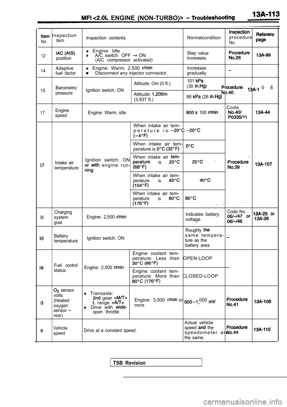
I n s p e c t i o n
itemNo.Inspection contentsNormalconditionp r o c e d u r e
No.
12position
l Engine: IdlelA/C switch: OFF ON(A/C compressor activated) Step value
increases.
14
15
17
Adaptivel Engine: Warm, 2,500 Increases
fuel factor
Disconnect any injector connector. gradually
Altitude: Om (0 ft.) 101Barometric
Ignition switch: ON (30
pressureAltitude:
0 8
(3,937 ft.)
88 (26
C o d eEngine
speedEngine: Warm, idle 100
When intake air tem-
p e r a t u r e i s
When intake air tern-
perature is
When intake air
Intake airIgnition switch: ON
e n g i n e r u n - is
temperature
When intake air tem-
peratureis
36
Charging
system
goal
When intake air tem-
peratureis
Code No.
Engine: 2,500 Indicates battery
voltage
Roughly
Batterys a m e t e m p e r a -
temperature Ignition switch: ON
ture as the
battery area
Engine coolant tem-
perature: Less than OPEN-LOOP
Fuel control
status Engine: 2,500 Engine coolant tem-
.
perature: More than CLOSED-LOOP
sensor
volts
(Heated
oxygen
sensor
rear)
l Transaxle: gear Engine: 3,500 or 000 range l Drive with more
open throttle
Actual vehicle
Vehicle
speedDrive at a constant speed. speed the
s p e e d o m e t e r a r e .
the same.
TSB Revision
Page 494 of 2103

ENGINE (NON-TURBO)> Troubleshooting
,
p a g eNo.
66
39
71
inspection
No.
Procedure
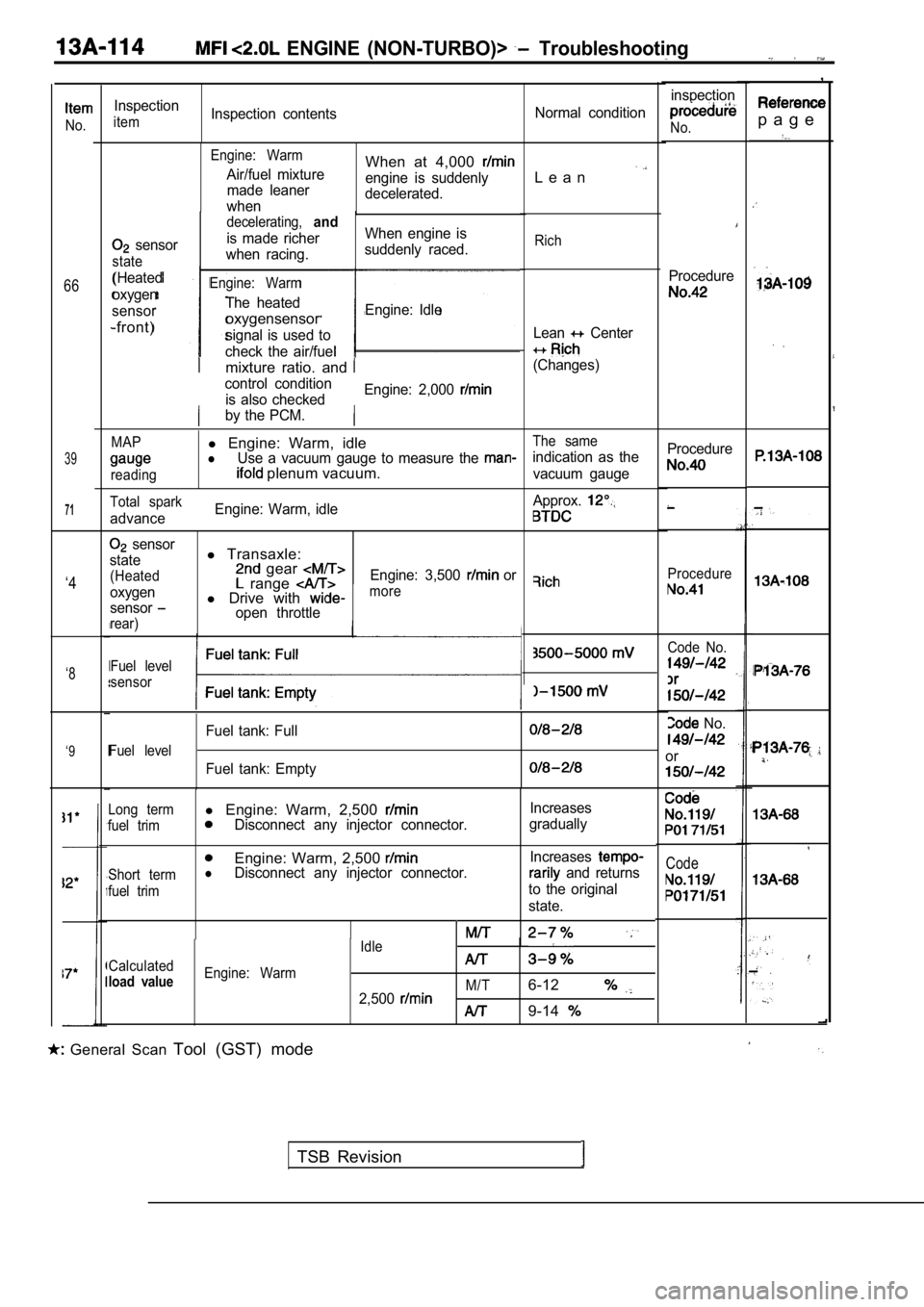
Inspection
itemInspection contentsNormal condition
Engine: Warm
Air/fuel mixture
made leaner
whenWhen at 4,000
engine is suddenly
decelerated.L e a n
sensor
state
(Heated
oxygen
sensor
-front)
decelerating,and
is made richer When engine is
when racing. suddenly raced.
Engine: Warm
The heated
oxygensensorEngine: Idle
signal is used to
check the air/fuel
Rich
Lean Center
(Changes)mixture ratio. and
control condition is also checked Engine: 2,000
by the PCM.
MAPl
Engine: Warm, idleThe same
lUse a vacuum gauge to measure the indication as the
reading plenum vacuum.vacuum gauge Procedure
Procedure
Total spark
advance
Engine: Warm, idle
Approx.
sensor
state
(Heated
oxygen
sensor
rear)
l Transaxle: gear range l Drive with open throttle Engine: 3,500
or‘4more
Code No.
No.
or
Fuel level
sensor‘8
Fuel level
Fuel tank: Full
Fuel tank: Empty
‘9
Code
Long terml
Engine: Warm, 2,500 Increases
fuel trimDisconnect any injector connector. gradually
Engine: Warm, 2,500
Short termlDisconnect any injector connector. Increases and returns
fuel trimto the original
state.
Idle
Calculated
load valueEngine: Warm M/T
2,5006-12
9-14
General Scan Tool (GST) mode
TSB Revision
Page 504 of 2103
ENGINE (NON-TURBO)> .
13100210139
COMPONENT LOCATION
Evaporative emission purge solenoid
Evaporative emission ventilation solenoid
Fuel pump relay
Heated oxygen sensor (Front)
Heated
sensor (Rear)
P a r k / N e u t r a l p o s i t i o n s w i t c h
(Transaxle range switch) ,
Power steering pressure switch ,
Powertrain control module
0Throttle position sensor
Vehicle speed sensor
NOTE
The “Name” column is in alphabetical order.
TSB Revision
Page 508 of 2103
28 of
( N O N - T U R B O ) >
Bottom view
of relay
I
Intake air temperature
RELAY RELAY)
RELAY CHE.
1. Remove the relay.
2.Check that there is (4) , and (6)
terminals..
Standard value:
.,
3.Use jumper leads to connect to
battery terminal and terminal
terminal.. . .
Check the continuity between
connecting and disconnecting the lead, at the,
battery
terminal. ,
Connected
DisconnectedContinuity
No continuity
4.If there is a defect, replace the (ASD) relay or fuel
pump relay.
INTAKE AIR TEMPERATURE SENSOR CHECK
1.Disconnect the intake air temperature sensor connec tor.
2. Measure the resistance between the sensor terminals.
Temperature Resistance
I 25 (77) 9 - 1 1I
I
INSTALLATION
1. Apply sealant to threaded portion.
Specified sealant: Loctite 24200 or equivalent
2. Install intake air temperature sensor and tighte n it to
specified torque.
Sensor tightening torque: 7 (5
3. Fasten harness connectors securely.
TSB Revision
Page 509 of 2103
On-vehicle Inspection of
ENGINE
TEMPERATURE SENSOR
CHECK
1. Disconnect the engine coolant temperature sensor
connector.
2. Measure the resistance between the sensor terminals.
INSTALLATION
1. Apply sealant to threaded
Specified sealant: Loctite 24200 or equivalent
2.
engine coolant sensor tighten
it to specified torque.
Sensor tightening torque: 7 (5
3. Fasten harness connectors securely.
THROTTLE POSITION SENSOR CHECK
1. the throttle position sensor connector.
2. Measure the resistance between the throttle posi tion
sensor side connector terminal 1 and terminal 3.
Standard value:
3. Measure the resistance between the throttle
sensor side, connector terminal 2 terminal 3.
Throttle valve slowly open until
fully open from the idle positionChanges smoothly in
t o t h e
angle of the
4. If the resistance is outside the standard value, ‘if it
doesn’t change smoothly, replace the throttle posit ion
sensor.
TSB Revision
Page 510 of 2103

On-vehicle of
ENGINE ( N O N - T U R B O ) >
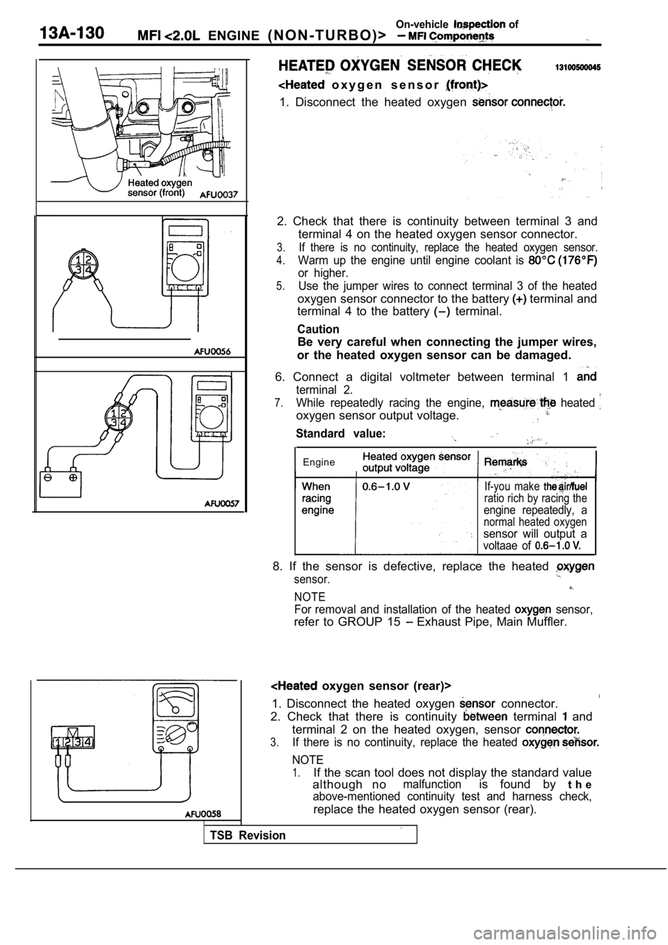
o x y g e n s e n s o r
1. Disconnect the heated oxygen
2. Check that there is continuity between terminal 3 and
terminal 4 on the heated oxygen sensor connector.
3.If there is no continuity, replace the heated oxyge n sensor.
4.Warm up the engine until engine coolant is
or higher.
5.Use the jumper wires to connect terminal 3 of the h eated
oxygen sensor connector to the battery terminal and
terminal 4 to the battery
terminal.
Caution
Be very careful when connecting the jumper wires,
or the heated oxygen sensor can be damaged.
6. Connect a digital voltmeter between terminal 1
terminal 2.
7.While repeatedly racing the engine, heated
oxygen sensor output voltage.
Standard value:
Engine
TSB Revision
If-you make
ratio rich by racing the
engine repeatedly, a
normal heated oxygen
sensor will output a
voltaae of
8. If the sensor is defective, replace the heated
sensor.
NOTE
For removal and installation of the heated sensor,
refer to GROUP 15 Exhaust Pipe, Main Muffler.
oxygen sensor (rear)>
1. Disconnect the heated oxygen
connector.
2. Check that there is continuity terminal and
terminal 2 on the heated oxygen, sensor
3.If there is no continuity, replace the heated
NOTE
1.If the scan tool does not display the standard valu e
although no
malfunctionis found by t h e
above-mentioned continuity test and harness check,
replace the heated oxygen sensor (rear).