1990 MITSUBISHI SPYDER sensor
[x] Cancel search: sensorPage 524 of 2103
ENGINE (TURBO)
AND
ENGINE> S e r v i c e
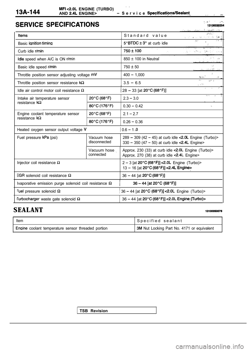
S t a n d a r d v a l u e
Basic at curb idle ,
Curb idle
speed when A/C is ON 850 100 in Neutral
Basic idle speed
750 50
Throttle position sensor adjusting voltage
Throttle position sensor resistance
400 1,000
3.5 6.5
Idle air control motor coil resistance 28 33 [at
Intake air temperature sensor
resistance2.3 3.0,
0.30 0.42
Engine coolant temperature sensor
resistance2.1 2.7
0.26 0.36
Heated oxygen sensor output voltage
0.6 1
Fuel pressure (psi) Vacuum hose disconnected289 309 (42 45) at curb idle Engine (Turbo)>
330
350 (47 50) at curb idle Engine>
Injector coil resistance
solenoid coil resistance
Vacuum hose Approx. 230 (33) at curb idle Engine (Turbo)>
connected Approx. 270 (38) at curb idle
Engine>
2
3 [at Engine (Turbo)>
13
16 [at
36 44 [at
TSB Revision
Ivaporative emission purge solenoid coil resistance
pressure solenoid 36 44 [at Engine (Turbo)>
waste gate solenoid 36 44 [at
SEALANT
Item
coolant temperature sensor threaded portion
S p e c i f i e d s e a l a n t
Nut Locking Part No. 4171 or equivalent
Page 527 of 2103
E N G I N E ( T U R B O )
AND
ENGINE>
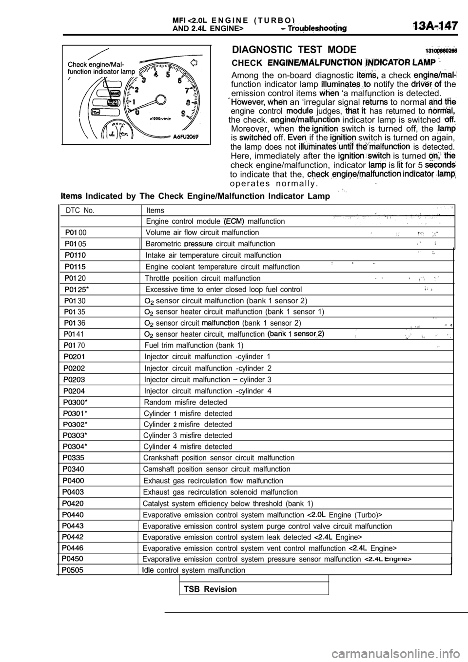
DIAGNOSTIC TEST MODE
CHECK
Among the on-board diagnostic a check
function indicator lamp notify the the
emission control items
‘a malfunction is detected.
an ‘irregular signal to normal
engine control judges, has returned to
the check. indicator lamp is switched
Moreover, when switch is turned off, the
is off. if the switch is turned on again,
the lamp does not is detected.
Here, immediately after the is turned
check engine/malfunction, indicator is for 5
to indicate that the,
o p e r a t e s n o r m a l l y .
Indicated by The Check Engine/Malfunction Indicato r Lamp
00
05
20
30
35
36
41
70
Items
Engine control module
malfunction
Volume air flow circuit malfunction
Barometric
circuit malfunction
Intake air temperature circuit malfunction
Engine coolant temperature circuit malfunction
Throttle position circuit malfunction
Excessive time to enter closed loop fuel control
sensor circuit malfunction (bank 1 sensor 2)
sensor heater circuit malfunction (bank 1 sensor 1 )
sensor circuit (bank 1 sensor 2).
sensor heater circuit, malfunction 1
Fuel trim malfunction (bank 1)
Injector circuit malfunction -cylinder 1
Injector circuit malfunction -cylinder 2
Injector circuit malfunction
cylinder 3
Injector circuit malfunction -cylinder 4
Random misfire detected
Cylinder
misfire detected
Cylinder
2misfire detected
Cylinder 3 misfire detected Cylinder 4 misfire detected
Crankshaft position sensor circuit malfunction
Camshaft position sensor circuit malfunction
Exhaust gas recirculation flow malfunction
Exhaust gas recirculation solenoid malfunction
Catalyst system efficiency below threshold (bank 1) Evaporative emission control system malfunction
Engine (Turbo)>
Evaporative emission control system purge control v alve circuit malfunction
Evaporative emission control system leak detected
Engine>
Evaporative emission control system vent control ma lfunction
Engine>
Evaporative emission control system pressure sensor malfunction
control system malfunction
DTC No.
TSB Revision
Page 528 of 2103
ENGINE (TURBO)
AND
ENGINE> Troubleshooting
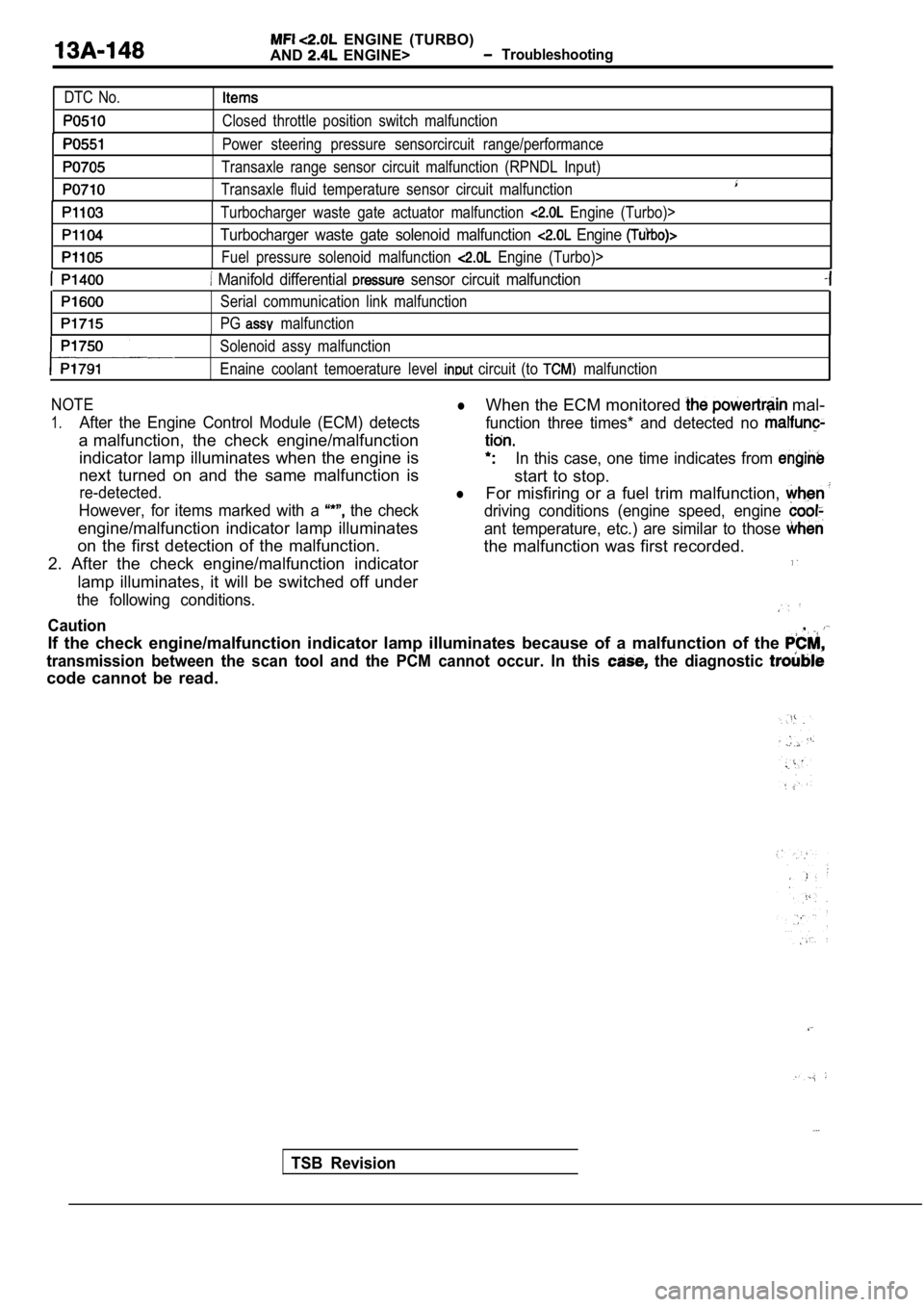
DTC No.
Closed throttle position switch malfunction
Power steering pressure sensorcircuit range/perfor mance
Transaxle range sensor circuit malfunction (RPNDL Input)
Transaxle fluid temperature sensor circuit malfunct ion
Turbocharger waste gate actuator malfunction Engine (Turbo)>
Turbocharger waste gate solenoid malfunction Engine
Fuel pressure solenoid malfunction Engine (Turbo)>
Manifold differential sensor circuit malfunction
Serial communication link malfunction
PG
malfunction
Solenoid assy malfunction
Enaine coolant temoerature level
circuit (to malfunction
NOTElWhen the ECM monitored mal-
1.After the Engine Control Module (ECM) detects function three times* and detected no
a malfunction, the check engine/malfunction
indicator lamp illuminates when the engine isIn this case, one time indicates from
next turned on and the same malfunction is
start to stop.
re-detected.lFor misfiring or a fuel trim malfunction,
However, for items marked with a the checkdriving conditions (engine speed, engine
engine/malfunction indicator lamp illuminatesant temperature, etc.) are similar to those
on the first detection of the malfunction. the malfunction was first recorded.
2. After the check engine/malfunction indicator
lamp illuminates, it will be switched off under
the following conditions.
Caution,
If the check engine/malfunction indicator lamp illu minates because of a malfunction of the
transmission between the scan tool and the PCM cann ot occur. In this the diagnostic
code cannot be read.
TSB Revision
Page 529 of 2103
E N G I N E
AND ENGINE>
ON-BOARD DIAGNOSTICS
The engine control module monitors the input/out-
put signals (some signals at all times and the othe rs
under specified conditions) of the engine control
module.
Whenamalfunction has continued for a specified
time or longer since the irregular signal is initia lly
monitored, the engine control module judges that
a malfunction has occurred.
After the ECM first detects a malfunction, a diagno s-
tic trouble code is recorded when the engine is
restarted and the same malfunction is re-detected.
However, for items marked with a
a diagnostic
trouble code is recorded on the first detection of
the malfunction.
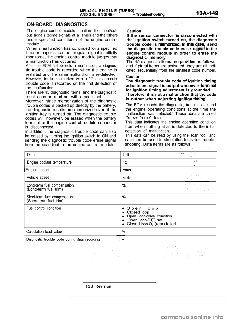
There are 45 diagnostic items, and the diagnostic results can be read out with a scan tool.
Moreover, since memorization of the diagnostic
trouble codes is backed up directly by the battery,
the diagnostic results are memorized even if the ignition key is turned off. The diagnostic trouble
codes will, however, be erased when the battery
terminal or the engine control module connector
is disconnected.
In addition, the diagnostic trouble code can also
be erased by turning the ignition switch to ON and
sending the diagnostic trouble code erase signal
from the scan tool to the engine control module.
Caution
If the sensor connector ‘is disconnected wlth
the’ ignition switch turned on, the diagnostic
trouble code is
In send
the diagnostic trouble code erase to the
engine control module in order to erase the
diagnostic memory.
The 45 diagnostic items are as follows,
and if plural items are activated, they are all ind i-
cated sequentially from the smallest code number.
Caution
The diagnostic trouble code of ignition
adjustment signal is output whenever
for ignition timing adjustment Is grounded.
Therefore, it is not a malfunction that the code
is output when adjusting
The ECM records the diagnostic, trouble code and
the engine operating conditions at the time the
malfunction was detected.’ These are called
“freeze frame” data.
This data indicates the engine operafing condition
from when nothing at all is detected to the initial
detection of malfunction.
This data can be read by using the scan tool, and
can then be used in simulation tests trouble-
shooting. Data items are as follows.,,
Data Unit
Engine coolant temperature.
Engine speed
Vehicle speed
Long-term fuel compensation
(Long-term fuel trim)
Short-term fuel compensation
(Short-term fuel trim)
km/h
Fuel control condition O p e n l o o p
l Closed loop
l Open loop-drive condition
l O p e n
set
l Closed
(rear) failed
Calculation load value
Diagnostic trouble code during data recording
TSB Revision
Page 535 of 2103
ENGINE (TURBO)
AND
ENGINE> Troubleshooting .
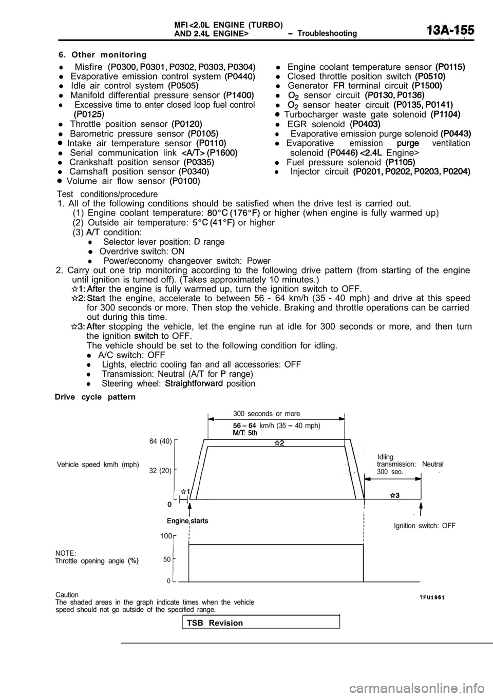
6. Other monitoring
lMisfire
l Evaporative emission control system
l Idle air control system
l Manifold differential pressure sensor
lExcessive time to enter closed loop fuel control
l Throttle position sensor
l Barometric pressure sensor
Intake air temperature sensor
l Serial communication link
l Crankshaft position sensor
l Camshaft position sensor
Volume air flow sensor
Test conditions/procedure
l Engine coolant temperature sensor
l Closed throttle position switch
l Generator terminal circuit
l sensor circuit
l sensor heater circuit
Turbocharger waste gate solenoid
l EGR solenoid
lEvaporative emission purge solenoid
l Evaporativeemissionventilation
solenoid Engine>
l Fuel pressure solenoid
lInjector circuit
1. All of the following conditions should be satisf ied when the drive test is carried out.
(1) Engine coolant temperature:
or higher (when engine is fully warmed up)
(2) Outside air temperature:
or higher
(3)
condition:
lSelector lever position: range
l Overdrive switch: ON
lPower/economy changeover switch: Power
2. Carry out one trip monitoring according to the f ollowing drive pattern (from starting of the engine
until ignition is turned off). (Takes approximately 10 minutes.)
the engine is fully warmed up, turn the ignition s witch to OFF.
the engine, accelerate to between 56 64 km/h (35 40 mph) and drive at this speed
for 300 seconds or more. Then stop the vehicle. Bra king and throttle operations can be carried
out during this time.
stopping the vehicle, let the engine run at idle f or 300 seconds or more, and then turn
the ignition
to OFF.
The vehicle should be set to the following conditio n for idling.
l A/C switch: OFF
lLights, electric cooling fan and all accessories: O FF
lTransmission: Neutral (A/T for range)
lSteering wheel: position
Drive cycle pattern
300 seconds or more
km/h (35 40 mph)
64 (40)
Idling
Vehicle speed km/h (mph) transmission: Neutral
32 (20)
300 seo.
,
Ignition switch: OFF
100
NOTE:Throttle opening angle 50
0
Caution
The shaded areas in the graph indicate times when t he vehicle
speed should not go outside of the specified range.
TSB Revision
Page 538 of 2103
ENGINE
A N D E N G I N E > .
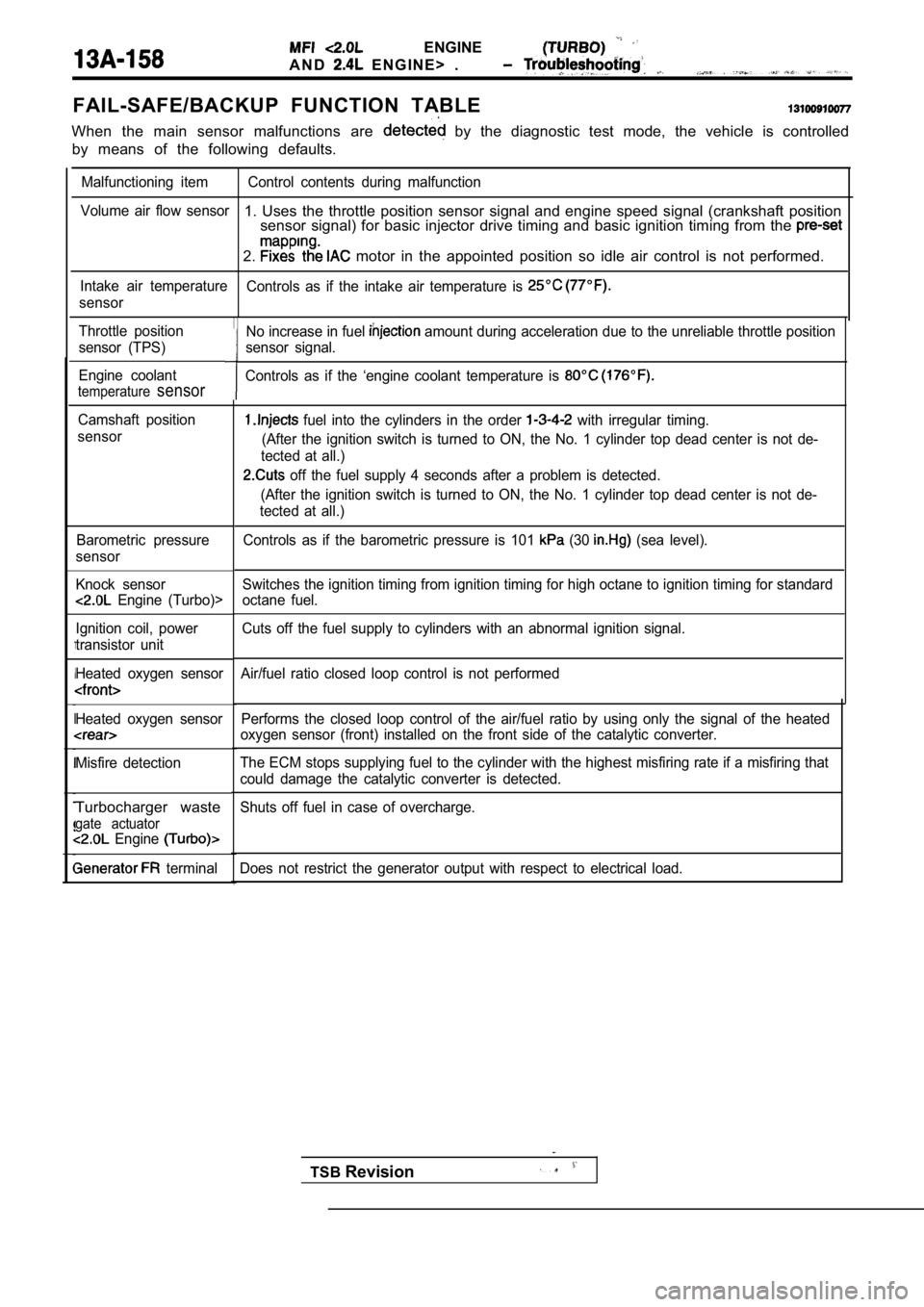
FAIL-SAFE/BACKUP FUNCTION TABLE
When the main sensor malfunctions are by the diagnostic test mode, the vehicle is controlled
by means of the following defaults.
Malfunctioning item Control contents during malfunct ion
Volume air flow sensor
1. Uses the throttle position sensor signal and eng ine speed signal (crankshaft position
sensor signal) for basic injector drive timing and basic ignition timing from the
2. motor in the appointed position so idle air contro l is not performed.
Intake air temperature
Controls as if the intake air temperature is
sensor
Throttle position
sensor (TPS)
Engine coolant
temperaturesensor
Camshaft position
sensor
Barometric pressure
sensor
Knock sensor
Engine (Turbo)>
Ignition coil, power
transistor unit
Heated oxygen sensor
Heated oxygen sensor
Misfire detection
Turbocharger waste
gate actuator Engine
terminal Performs the closed loop control of the air/fuel ra
tio by using only the signal of the heated
oxygen sensor (front) installed on the front side o f the catalytic converter.
The ECM stops supplying fuel to the cylinder with t he highest misfiring rate if a misfiring that
could damage the catalytic converter is detected.
Shuts off fuel in case of overcharge.
Does not restrict the generator output with respect to electrical load.
No increase in fuel amount during acceleration due to the unreliable throttle position
sensor signal.
Controls as if the ‘engine coolant temperature is
fuel into the cylinders in the order with irregular timing.
(After the ignition switch is turned to ON, the No. 1 cylinder top dead center is not de-
tected at all.)
off the fuel supply 4 seconds after a problem is d etected.
(After the ignition switch is turned to ON, the No. 1 cylinder top dead center is not de-
tected at all.)
Controls as if the barometric pressure is 101
(30 (sea level).
Switches the ignition timing from ignition timing f or high octane to ignition timing for standard
octane fuel.
Cuts off the fuel supply to cylinders with an abnor mal ignition signal.
Air/fuel ratio closed loop control is not performed
TSB Revision
Page 539 of 2103
ENGINE (TURBO)
AND
ENGINE> Troubleshooting
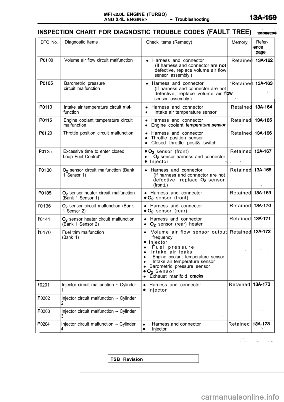
INSPECTION CHART FOR DIAGNOSTIC TROUBLE CODES (FAULT TREE)
DTC No.Diagnostic items Check items (Remedy) MemoryRefer-
,
00Volume air flow circuit malfunctionl Harness and connector
R e t a i n e d
(If harness and connector are not
defective, replace volume air flow
sensor assembly.)
Barometric pressurel Harness and connector
‘ R e t a i n e d
circuit malfunction(If harness and connector are not
defective, replace volume air ,
sensor assembly.)
Intake air temperature circuit l Harness and connector R e t a i n e d
functionlIntake air temperature sensor
Engine coolant temperature circuitl Harness and connector
Retained
malfunctionl Engine coolant
20Throttle position circuit malfunctionl Harness and connector R e t a i n e dl Throttle position sensor
l Closed throttle posit& switch
25
30
‘0136
‘0141
‘0170
Excessive time to enter closed sensor (front) R e t a i n e d
Loop Fuel Control*l sensor harness and connector
I n j e c t o r
sensor circuit malfunction (Bankl
Harness and connector R e t a i n e d
1 Sensor 1)(If harness and connector are not
d e f e c t i v e , r e p l a c e
s e n s o r
(front).)
sensor heater circuit malfunctionl Harness and connector R e t a i n e d
(Bank 1 Sensor 1) sensor (front)
sensor circuit malfunction (Bankl Harness and connector R e t a i n e d
1 Sensor 2) sensor (rear)
sensor heater circuit malfunctionl
Harness and connector R e t a i n e d
(Bank 1 Sensor 2)l sensor (rear) heater
Fuel trim malfunctionl
V o l u m e a i r f l o w s e n s o r o u t p u t R e t a i n e d
(Bank 1)frequency
I n j e c t o r
l F u e l p r e s s u r e
l I n t a k e a i r l e a k s
lEngine coolant temperature sensorlIntake air temperature sensor
l Barometric pressure sensor
S e n s o r
l Exhaust manifold
‘0201 Injector circuit malfunction Cylinderl
Harness and connector R e t a i n e d
1 I n j e c t o r
‘0202Injector circuit malfunction Cylinder
2
‘0203Injector circuit malfunction Cylinder.
3
‘0204Injector circuit malfunction CylinderlHarness and connector R e t a i n e d
4Injector
TSB Revision
Page 540 of 2103
ENGINE (TURBO)
AND ENGINE> Troubleshooting
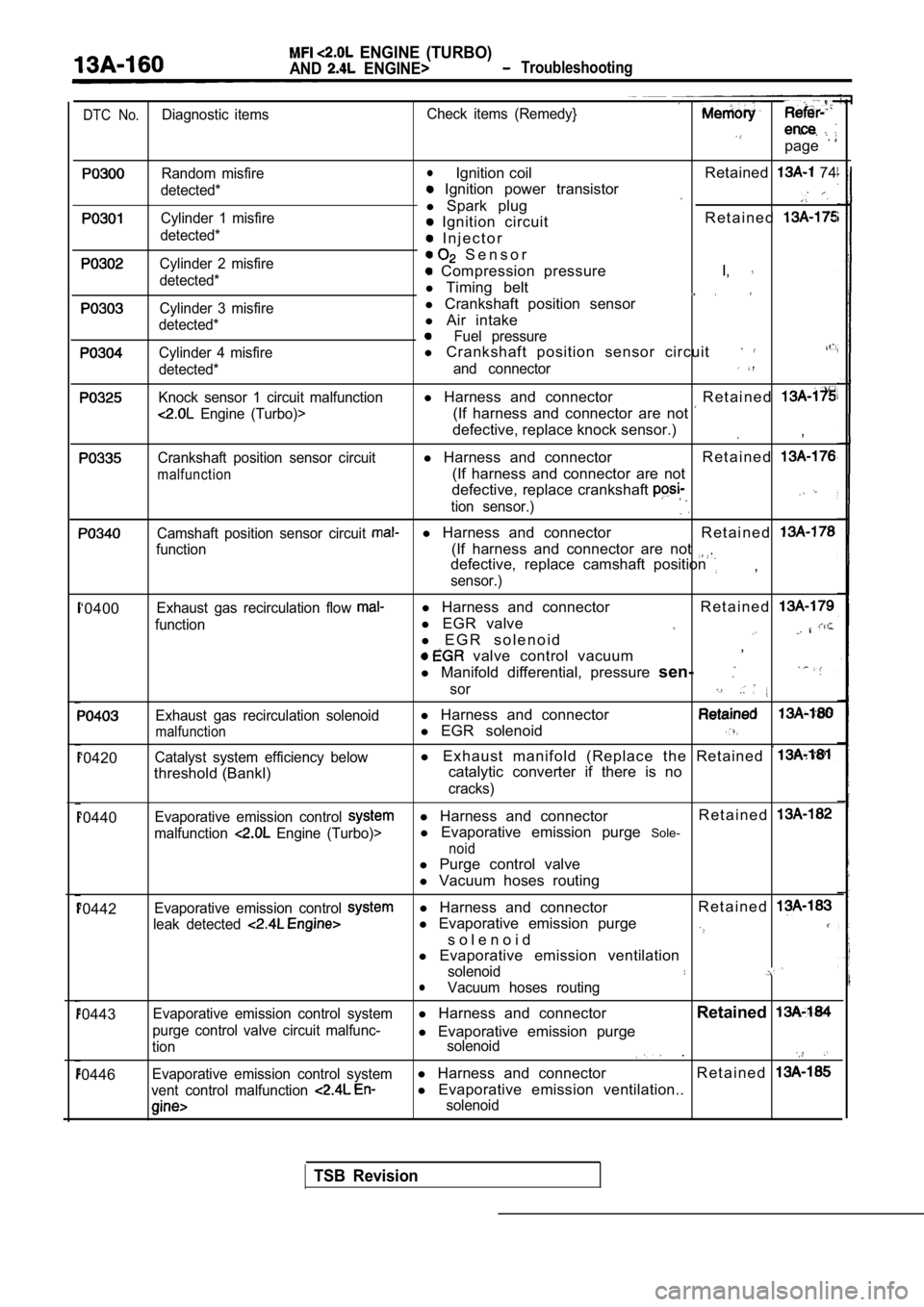
DTC No.Diagnostic itemsCheck items (Remedy}
page
Random misfire
detected*
Cylinder 1 misfire
detected*
Cylinder 2 misfire
detected*
Cylinder 3 misfire
detected*
Cylinder 4 misfire
detected*
Knock sensor 1 circuit malfunction
Engine (Turbo)>
Crankshaft position sensor circuit
malfunction
lIgnition coil Retained 74
Ignition power transistor
l Spark plug
R e t a i n e d Ignition circuit
I n j e c t o r
S e n s o r
Compression pressure I,
l
Timing belt
l Crankshaft position sensor
l Air intake
Fuel pressure
l Crankshaft position sensor circuit
and connector
l Harness and connector R e t a i n e d
(If harness and connector are not
defective, replace knock sensor.),
l Harness and connector R e t a i n e d
(If harness and connector are not
defective, replace crankshaft
tion sensor.)
Camshaft position sensor circuit l Harness and connector R e t a i n e d
function(If harness and connector are not defective, replace camshaft position
sensor.),
‘0400
‘0420
Exhaust gas recirculation flow
function
Exhaust gas recirculation solenoid
malfunction
Catalyst system efficiency below
threshold (Bankl) l
Harness and connector R e t a i n e d
l
EGR valve
l E G R s o l e n o i d
valve control vacuum ,
l Manifold differential, pressure sen-
sor
l Harness and connector
l EGR solenoid
l E x h a u s t m a n i f o l d ( R e p l a c e t h e R e t a i n e d
catalytic converter if there is no
cracks)
‘0440Evaporative emission control l Harness and connector R e t a i n e d
malfunction Engine (Turbo)>l
Evaporative emission purge Sole-
noid
l Purge control valve
l Vacuum hoses routing
‘0442
‘0443
‘0446
Evaporative emission control l Harness and connector R e t a i n e d
leak detected l
Evaporative emission purge
s o l e n o i d
l Evaporative emission ventilation
solenoidlVacuum hoses routing
Evaporative emission control system
l Harness and connector Retained
purge control valve circuit malfunc-l
Evaporative emission purgetion solenoid .
Evaporative emission control systeml
Harness and connector R e t a i n e d
vent control malfunction l
Evaporative emission ventilation..
solenoid
TSB Revision