Page 774 of 2103

A u t o - c r u i s e C o n t r o l S y s t e m
1.
2.
Remove the link protector. (Refer to
Check the slack in each of the inner cables in the
accelerator cable, auto-cruise control cable and th rottle
cable.
If the slack in an inner cable is excessive, or if there
is no play, loosen the adjusting bolts and the nuts in
the throttle lever and each link, to release the th rottle
lever and each link. (The bolts and nuts should not be
removed.)
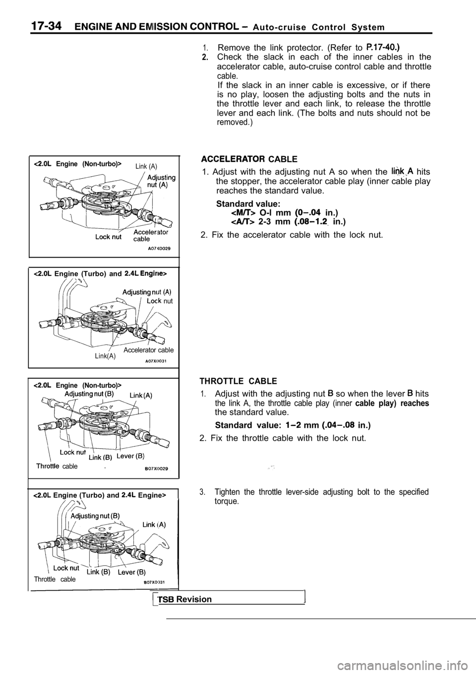
Engine (Non-turbo)>Link (A)
Engine (Turbo) and
nut
Accelerator cableLink(A)
Engine (Non-turbo)>
cable.
Engine (Turbo) and Engine>
Throttle cable
CABLE
1. Adjust with the adjusting nut A so when the
hits
the stopper, the accelerator cable play (inner cabl e play
reaches the standard value.
Standard value:
O-l mm in.)
2-3 mm in.)
2. Fix the accelerator cable with the lock nut.
THROTTLE CABLE
1.Adjust with the adjusting nut so when the lever hits
the link A, the throttle cable play (inner cable play) reaches
the standard value. Standard value:
mm in.)
2. Fix the throttle cable with the lock nut.
3.Tighten the throttle lever-side adjusting bolt to t he specified
torque.
Revision
Page 795 of 2103

Emission Control
Engine
C H E C K . .
To ensure proper operation of system, all
and moving parts must be free of
plugging or sticking.
Ensure that the system’ hoses do not leak.
Replace leaking components.
1.Check the EGR and valve with
engine fully warmed up and running coolant
perature over
2.With the transaxle in neutral and the allow.
the engine to idle seconds.
3. Abruptly accelerate the engine
approximately
but not over 3000
4, The valve ‘stem should move when accelerating
the engine. Repeat the test several- times-to
movement.
5.If the EGR valve stem moves, the control system is
ing normally.
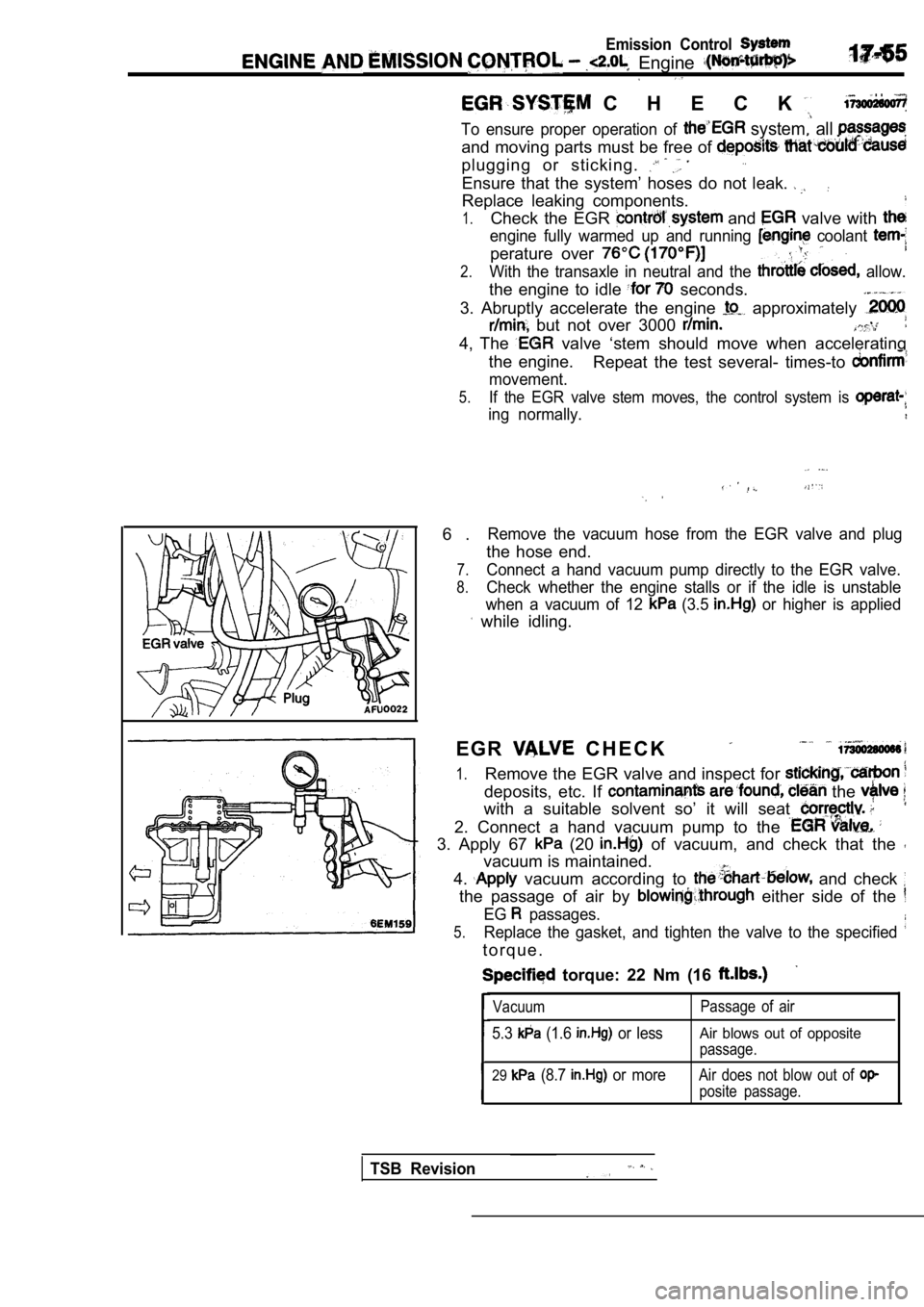
6 .Remove the vacuum hose from the EGR valve and plug
the hose end.
7.Connect a hand vacuum pump directly to the EGR valv e.
8.Check whether the engine stalls or if the idle is unstable
when a vacuum of 12
(3.5 or higher is applied
while idling.
E G R
C H E C K
1.Remove the EGR valve and inspect for
deposits, etc. If the
with a suitable solvent so’ it will seat
2. Connect a hand vacuum pump to the
3. Apply 67 (20 of vacuum, and check that the
vacuum is maintained.
4.
vacuum according to and check
the passage of air by either side of the
EG passages.
5.Replace the gasket, and tighten the valve to the sp ecified
t o r q u e .
torque: 22 Nm (16
Vacuum
5.3 (1.6 or less
Passage of air
Air blows out of opposite
passage.
29 (8.7 or moreAir does not blow out of
posite passage.
TSB Revision
Page 806 of 2103
1 7 - 6 6 AND (Turbo) and
Engine (Turbo)>CRANKCASE VENTILATION SYSTEM CHECK
1.
2.
3.
4.
5.
17900110198
Remove the positive crankcase ventilation (PCV) val ve
from the rocker cover, then reconnect the PCV valve
to the vacuum supply hose (ventilation hose).
With the engine idling, put finger on the open end of
the PCV valve, and check for negative pressure (vacuum)
with finger.
NOTE
At this time, the plunger in the PCV valve should m ove
back and forth as the open end is covered and uncov ered.
If negative pressure is not felt, clean or replace the PCV
valve. Inspect the vacuum supply hose and vacuum su pply
hose port for restriction or plugged condition.
Install the PCV valve.
Tighten it to the specified torque. ‘Engine (Turbo)>
Specified torque: Nm (7.2
Revision
Page 824 of 2103
(Turbo) and Engine>
EGR VALVE CHECK
1.Remove the EGR valve and inspect for sticking, carbon
deposits, etc. If contaminants are found, clean the valve
with a suitable solvent so it will seat correctly.
2. Connect a hand vacuum pump to the EGR valve.
3. Apply 67
(20 of vacuum, and check to be
sure that the vacuum is maintained.
4. Apply vacuum according to the
below and check
the passage of air by blowing through either side o f the
EG
passages.
Vacuum Passage of air
5.3 (1.6 or lessAir does not blow out of op-
posite passage.
27 (7.9 or more
Air blows out of opposite
passage.,
5.Replace the gasket, and tighten the valve to the sp ecified
torque.
Specified torque: 22 Nm (16
TSB Revision
Page 845 of 2103
OVERHAUL
CONTENTS
CLUTCH. . . . . . . . . . . . . . . . . . . . . . . . . . . . ...*...4SPECIFICATIONS2. . . . . . . . . . . . .
CLUTCH RELEASE CYLINDER
Engine (Turbo) and Engine> . . .
3
Lubricants . . . . . . . . . . . . . . . . . . . .
. . . . . . . . . . . . .
Service Specifications
Engine (Turbo) and Engine> . . . . . 2
Torque Specifications . . . . . . . , . . . . . . . . . . . . . . .2
Page 846 of 2103
21CLUTCH OVERHAUL Specifications
SPECIFICATIONS21200030047
SERVICE SPECIFICATION Engine (Turbo) and Engine>
0.3
Diaphragm spring end height difference
TORQUE SPECIFICATIONS
Engine (Turbo) and Engine>
Clutch cover bolt
Release cylinder mounting bolt
Release cylinder union bolt
Release cylinder bleeder plug
Release fork fulcrum
Clutch chamber bracket mountingbolt
Clutch line tube flare nut
N mft.
19 14
19
14
23
17
118.0
36 24
1914
1511
Engine (Non-turbo)>
Drive plate to clutch flywheel bolt
Revision
Page 891 of 2103

T R A N S A X L E
CONTENTS
CENTER DIFFERENTIAL . . . . . .60
CLUTCH HOUSING. . . . . . . . . . . . . . . . . . . . . . .65
DIFFERENTIAL. . . . . . . . . . . . . . . . . .57. . . . . . . .
DRIVE BEVEL GEAR
. . . . . . . . . . .76
DRIVEN BEVEL GEAR . . . . . . . . . .80
EXTENSION. . . . . . . . . .73
SYNCHRONIZER . . . . . . . . . . . . . .36
FRONT OUTPUT SHAFT . . . . . . . .56
GENERAL INFORMATION. . . . . . . . . . . . . . . . . .2
INPUT SHAFT
. . . . . . . . . . . . . . . . . . . . . . . . . . . .38
INTERMEDIATE GEAR. . . . . . . . . . . . . . . . . . . .48
OUTPUT SHAFT . . . . . . . . .
55
SHIFT 3SPECIAL TOOLS
. . . . . . . . . . . . . . . . . . . . . . . . . .13
SPECIFICATIONS. . . . . . . . . . . . . . . . . ... . . . . . . .
G e a r R a t i o T a b l e . . .
...
. . . . . . . . . . . . . . . . . . . . . .5
Sealants and Adhesives . . . . . . . . . . . . . . . . . . . . .13
Service Specifications . . . . . . .6
Service Specifications . . . . .. . . . . . . .6
Snap Rings and Spacers for . . . . . . . . . . . . . . . . . . . . . . . . . . . . . . . . . . . . . . . . . . . . . .7
Torque Specifications. . . . . . . . . . . . . . . . . . . . . . . .12
Transaxle Model Table. . . . . . . . . . . . . .. . . . . . .5
SPEEDOMETER GEAR. . . . . . . . . . . . . . . . . . . .64
TRANSAXLE. . . . . . . . . . . . . . . . . . . . . . . . . .
. . . .17
TRANSFER . . . . . . . . . . . . . . . . . . . 68
TRANSFER CASE . . . . . . . . . . . . .
TRANSFER CASE ADAPTER .. . . . . . . . . . .. . . . . . . . . . . . . . . . . . . . . .76
Page 896 of 2103
MANUAL, TRANSAXLE OVERHAUL
Items
Differential case preload mm (in.)
Differential pinion backlash mm (in.)
Input shaft front bearing end play
mm (in.)
Input shaft end play
mm (in.)
Input shaft rear bearing end play mm (in.)
Intermediate gear bearing end play
mm (in.)
Intermediate gear bearing end play
mm (in.)
Intermediate gear preload mm (in.)
shaft preload mm (in.)
Standard value .
Center differential case end play mm (in.)
Center differential side gear end play mm (in.)
Front differential case end play mm (in.)
Front differential pinion backlash mm (in.)
Front output shaft preload mm (in.)
Input shaft end play mm (in.)
Input shaft front bearing end play mm (in.)
Input shaft rear bearing end play mm (in.) Intermediate gear bearing end play mrn (in.)
Intermediate gear preload mm (in.)
Transfer bevel gear set backlash mm (in.)
drive bevel gear rotating torque Nm
driven bevel gear rotating torque Nm
coupling end play mm (in.) Standard value
1.7-2.5
TSB Revision